NISSAN PICK-UP 1998 Owner's Manual
PICK-UP 1998
NISSAN
NISSAN
https://www.carmanualsonline.info/img/5/57374/w960_57374-0.png
NISSAN PICK-UP 1998 Owner's Manual
Trending: engine coolant, radio controls, service, lug pattern, fuse box location, coolant temperature, dead battery
Page 21 of 1659
Removal and Installation
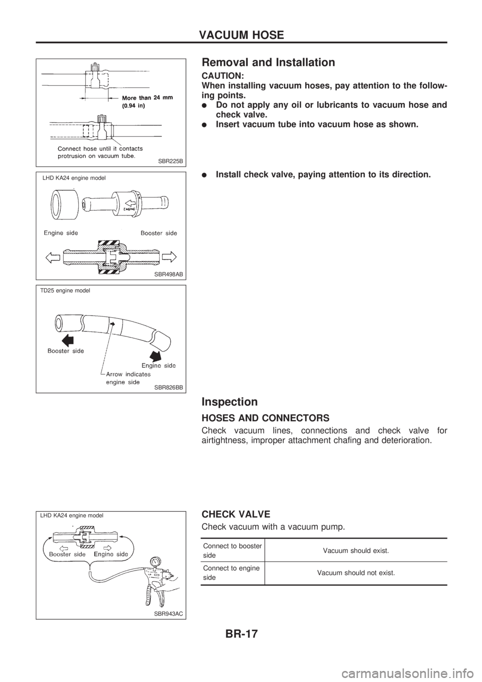
CAUTION:
When installing vacuum hoses, pay attention to the follow-
ing points.
lDo not apply any oil or lubricants to vacuum hose and
check valve.
lInsert vacuum tube into vacuum hose as shown.
lInstall check valve, paying attention to its direction.
Inspection
HOSES AND CONNECTORS
Check vacuum lines, connections and check valve for
airtightness, improper attachment chafing and deterioration.
CHECK VALVE
Check vacuum with a vacuum pump.
Connect to booster
sideVacuum should exist.
Connect to engine
sideVacuum should not exist.
SBR225B
SBR498AB
.LHD KA24 engine model
SBR826BB
.TD25 engine model
SBR943AC
.LHD KA24 engine model.
VACUUM HOSE
BR-17
Page 22 of 1659
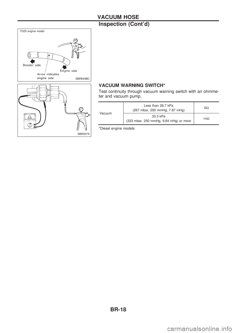
VACUUM WARNING SWITCH*
Test continuity through vacuum warning switch with an ohmme-
ter and vacuum pump.
VacuumLess than 26.7 kPa
(267 mbar, 200 mmHg, 7.87 inHg)0W
33.3 kPa
(333 mbar, 250 mmHg, 9.84 inHg) or more
W
*Diesel engine models
SBR844BC
.
.TD25 engine model
SBR007A
VACUUM HOSE
Inspection (Cont'd)
BR-18
Page 23 of 1659
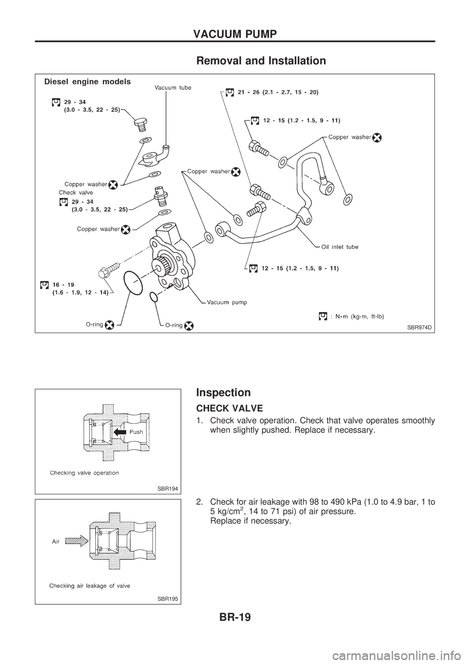
Removal and Installation
Inspection
CHECK VALVE
1. Check valve operation. Check that valve operates smoothly
when slightly pushed. Replace if necessary.
2. Check for air leakage with 98 to 490 kPa (1.0 to 4.9 bar, 1 to
5 kg/cm
2, 14 to 71 psi) of air pressure.
Replace if necessary.
SBR974D
SBR194
SBR195
VACUUM PUMP
BR-19
Page 24 of 1659
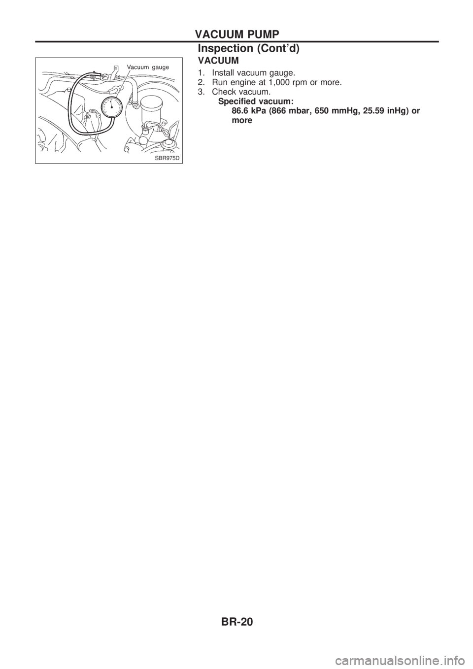
VACUUM
1. Install vacuum gauge.
2. Run engine at 1,000 rpm or more.
3. Check vacuum.
Specified vacuum:
86.6 kPa (866 mbar, 650 mmHg, 25.59 inHg) or
more
SBR975D
VACUUM PUMP
Inspection (Cont'd)
BR-20
Page 25 of 1659
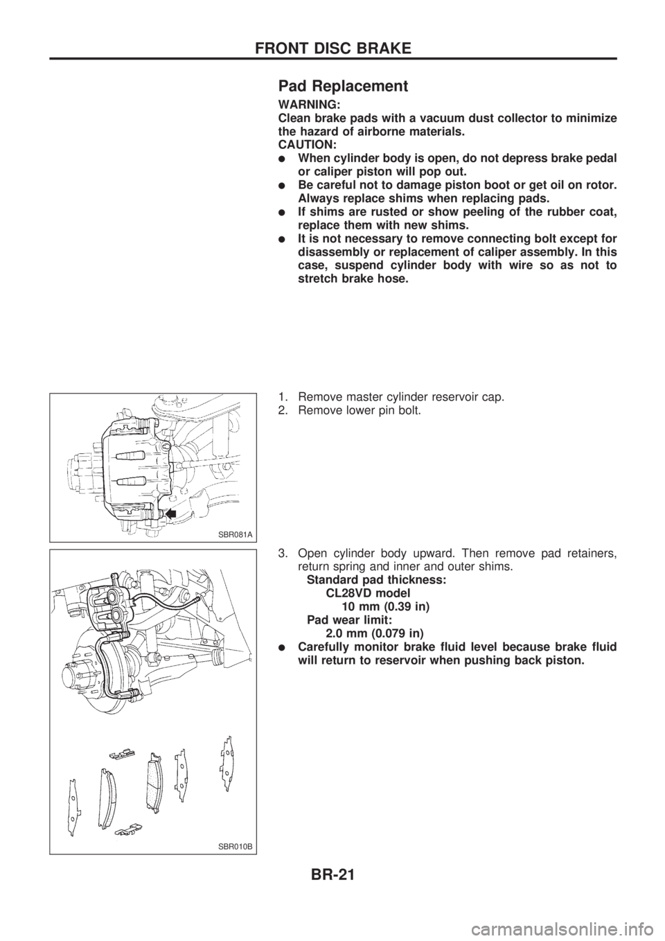
Pad Replacement
WARNING:
Clean brake pads with a vacuum dust collector to minimize
the hazard of airborne materials.
CAUTION:
lWhen cylinder body is open, do not depress brake pedal
or caliper piston will pop out.
lBe careful not to damage piston boot or get oil on rotor.
Always replace shims when replacing pads.
lIf shims are rusted or show peeling of the rubber coat,
replace them with new shims.
lIt is not necessary to remove connecting bolt except for
disassembly or replacement of caliper assembly. In this
case, suspend cylinder body with wire so as not to
stretch brake hose.
1. Remove master cylinder reservoir cap.
2. Remove lower pin bolt.
3. Open cylinder body upward. Then remove pad retainers,
return spring and inner and outer shims.
Standard pad thickness:
CL28VD model
10 mm (0.39 in)
Pad wear limit:
2.0 mm (0.079 in)
lCarefully monitor brake fluid level because brake fluid
will return to reservoir when pushing back piston.
SBR081A
SBR010B
FRONT DISC BRAKE
BR-21
Page 26 of 1659
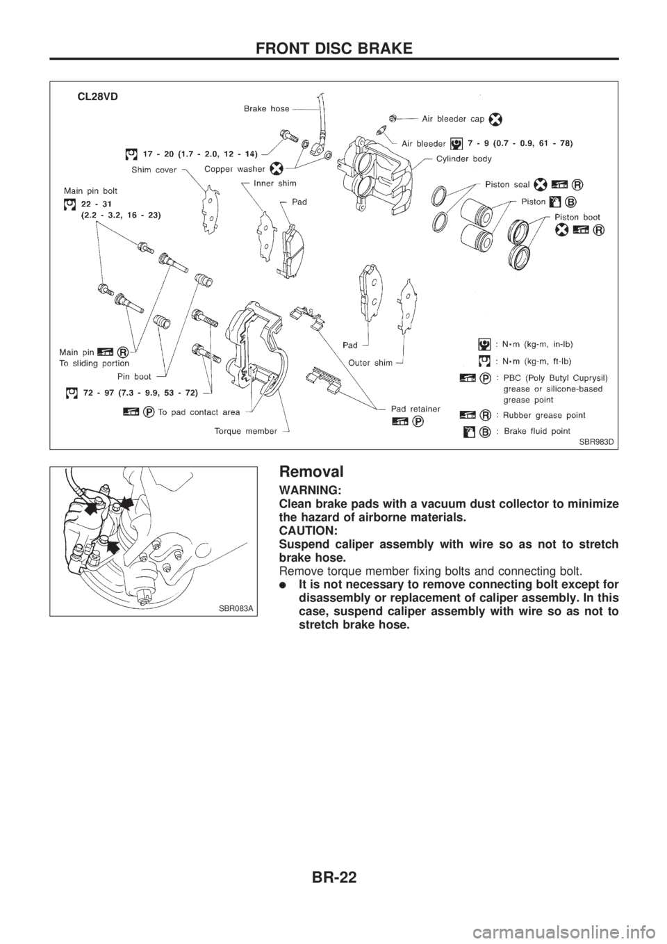
Removal
WARNING:
Clean brake pads with a vacuum dust collector to minimize
the hazard of airborne materials.
CAUTION:
Suspend caliper assembly with wire so as not to stretch
brake hose.
Remove torque member fixing bolts and connecting bolt.
lIt is not necessary to remove connecting bolt except for
disassembly or replacement of caliper assembly. In this
case, suspend caliper assembly with wire so as not to
stretch brake hose.
SBR983D
SBR083A
FRONT DISC BRAKE
BR-22
Page 27 of 1659
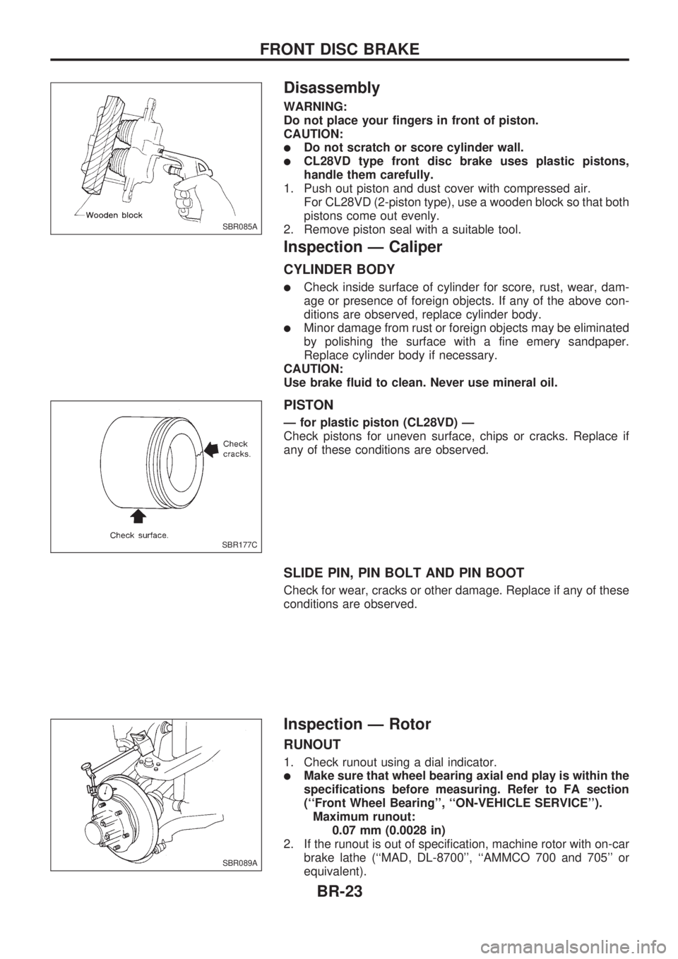
Disassembly
WARNING:
Do not place your fingers in front of piston.
CAUTION:
lDo not scratch or score cylinder wall.
lCL28VD type front disc brake uses plastic pistons,
handle them carefully.
1. Push out piston and dust cover with compressed air.
For CL28VD (2-piston type), use a wooden block so that both
pistons come out evenly.
2. Remove piston seal with a suitable tool.
Inspection Ð Caliper
CYLINDER BODY
lCheck inside surface of cylinder for score, rust, wear, dam-
age or presence of foreign objects. If any of the above con-
ditions are observed, replace cylinder body.
lMinor damage from rust or foreign objects may be eliminated
by polishing the surface with a fine emery sandpaper.
Replace cylinder body if necessary.
CAUTION:
Use brake fluid to clean. Never use mineral oil.
PISTON
Ð for plastic piston (CL28VD) Ð
Check pistons for uneven surface, chips or cracks. Replace if
any of these conditions are observed.
SLIDE PIN, PIN BOLT AND PIN BOOT
Check for wear, cracks or other damage. Replace if any of these
conditions are observed.
Inspection Ð Rotor
RUNOUT
1. Check runout using a dial indicator.
lMake sure that wheel bearing axial end play is within the
specifications before measuring. Refer to FA section
(``Front Wheel Bearing'', ``ON-VEHICLE SERVICE'').
Maximum runout:
0.07 mm (0.0028 in)
2. If the runout is out of specification, machine rotor with on-car
brake lathe (``MAD, DL-8700'', ``AMMCO 700 and 705'' or
equivalent).
SBR085A
SBR177C
SBR089A
FRONT DISC BRAKE
BR-23
Page 28 of 1659
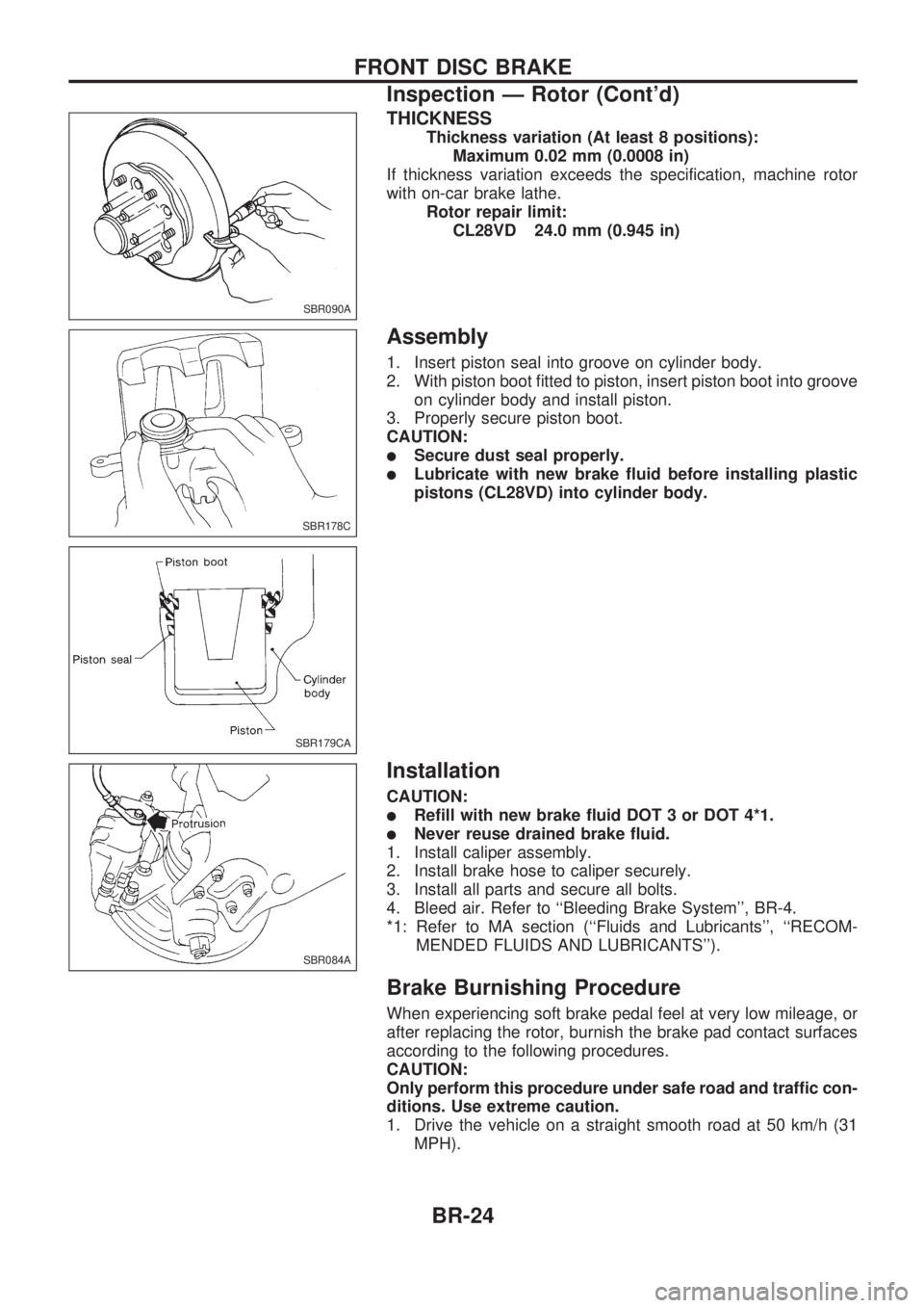
THICKNESS
Thickness variation (At least 8 positions):
Maximum 0.02 mm (0.0008 in)
If thickness variation exceeds the specification, machine rotor
with on-car brake lathe.
Rotor repair limit:
CL28VD 24.0 mm (0.945 in)
Assembly
1. Insert piston seal into groove on cylinder body.
2. With piston boot fitted to piston, insert piston boot into groove
on cylinder body and install piston.
3. Properly secure piston boot.
CAUTION:
lSecure dust seal properly.
lLubricate with new brake fluid before installing plastic
pistons (CL28VD) into cylinder body.
Installation
CAUTION:
lRefill with new brake fluid DOT 3 or DOT 4*1.
lNever reuse drained brake fluid.
1. Install caliper assembly.
2. Install brake hose to caliper securely.
3. Install all parts and secure all bolts.
4. Bleed air. Refer to ``Bleeding Brake System'', BR-4.
*1: Refer to MA section (``Fluids and Lubricants'', ``RECOM-
MENDED FLUIDS AND LUBRICANTS'').
Brake Burnishing Procedure
When experiencing soft brake pedal feel at very low mileage, or
after replacing the rotor, burnish the brake pad contact surfaces
according to the following procedures.
CAUTION:
Only perform this procedure under safe road and traffic con-
ditions. Use extreme caution.
1. Drive the vehicle on a straight smooth road at 50 km/h (31
MPH).
SBR090A
SBR178C
SBR179CA
SBR084A
FRONT DISC BRAKE
Inspection Ð Rotor (Cont'd)
BR-24
Page 29 of 1659
2. Use medium brake pedal/foot effort to bring the vehicle to a
complete stop from 50 km/h (31 MPH). Adjust brake pedal/
foot pressure such that vehicle stopping time equals 3 to 5
seconds.
3. To cool the brake system, drive the vehicle at 50 km/h (31
MPH) for 1 minute without stopping.
4. Repeat steps 1 to 3 10 times or more to complete the bur-
nishing procedure.
FRONT DISC BRAKE
Brake Burnishing Procedure (Cont'd)
BR-25
Page 30 of 1659
SBR978D
SBR979D
REAR DRUM BRAKE
BR-26
Trending: drain bolt, lights, change wheel, radio, trunk, hood open, wheel
