check oil NISSAN PICK-UP 1998 Owner's Manual
[x] Cancel search | Manufacturer: NISSAN, Model Year: 1998, Model line: PICK-UP, Model: NISSAN PICK-UP 1998Pages: 1659, PDF Size: 53.39 MB
Page 426 of 1659
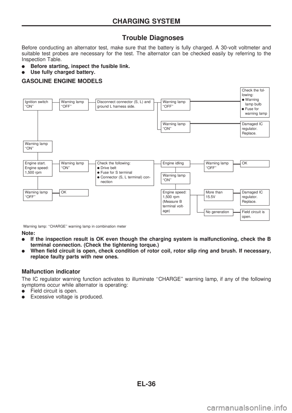
Trouble Diagnoses
Before conducting an alternator test, make sure that the battery is fully charged. A 30-volt voltmeter and
suitable test probes are necessary for the test. The alternator can be checked easily by referring to the
Inspection Table.
lBefore starting, inspect the fusible link.
lUse fully charged battery.
GASOLINE ENGINE MODELS
Check the fol-
lowing:
lWarning
lamp bulb
lFuse for
warning lamp
Ignition switch
``ON''Warning lamp
``OFF''Disconnect connector (S, L) and
ground L harness side.Warning lamp
``OFF''
Warning lamp
``ON''Damaged IC
regulator.
Replace.
Warning lamp
``ON''
Engine start.
Engine speed:
1,500 rpmWarning lamp
``ON''Check the following:lDrive beltlFuse for S terminallConnector (S, L terminal) con-
nection
Engine idlingWarning lamp
``OFF''OK
Warning lamp
``ON''
Warning lamp
``OFF''OKEngine speed:
1,500 rpm
(Measure B
terminal volt-
age)More than
15.5VDamaged IC
regulator.
Replace.
No generationField circuit is
open.
Warning lamp: ``CHARGE'' warning lamp in combination meter
Note:
lIf the inspection result is OK even though the charging system is malfunctioning, check the B
terminal connection. (Check the tightening torque.)
lWhen field circuit is open, check condition of rotor coil, rotor slip ring and brush. If necessary,
replace faulty parts with new ones.
Malfunction indicator
The IC regulator warning function activates to illuminate ``CHARGE'' warning lamp, if any of the following
symptoms occur while alternator is operating:
lField circuit is open.
lExcessive voltage is produced.
CHARGING SYSTEM
EL-36
Page 427 of 1659
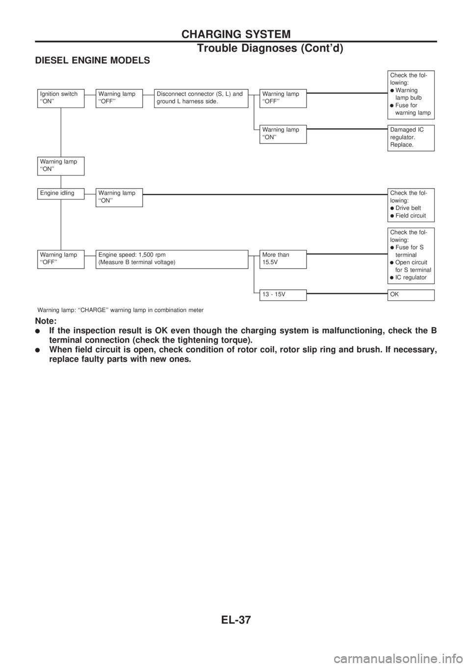
DIESEL ENGINE MODELS
Check the fol-
lowing:
lWarning
lamp bulb
lFuse for
warning lamp
Ignition switch
``ON''Warning lamp
``OFF''Disconnect connector (S, L) and
ground L harness side.Warning lamp
``OFF''
Warning lamp
``ON''Damaged IC
regulator.
Replace.
Warning lamp
``ON''
Engine idlingWarning lamp
``ON''Check the fol-
lowing:
lDrive beltlField circuit
Check the fol-
lowing:
lFuse for S
terminal
lOpen circuit
for S terminal
lIC regulator
Warning lamp
``OFF''Engine speed: 1,500 rpm
(Measure B terminal voltage)More than
15.5V
13 - 15VOK
Warning lamp: ``CHARGE'' warning lamp in combination meter
Note:
lIf the inspection result is OK even though the charging system is malfunctioning, check the B
terminal connection (check the tightening torque).
lWhen field circuit is open, check condition of rotor coil, rotor slip ring and brush. If necessary,
replace faulty parts with new ones.
CHARGING SYSTEM
Trouble Diagnoses (Cont'd)
EL-37
Page 506 of 1659
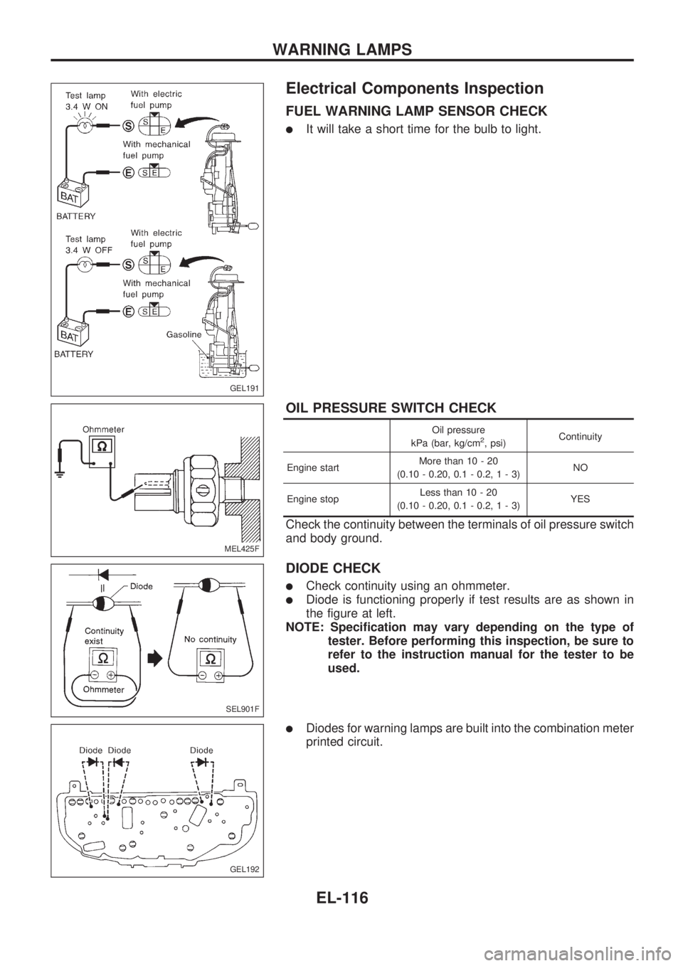
Electrical Components Inspection
FUEL WARNING LAMP SENSOR CHECK
lIt will take a short time for the bulb to light.
OIL PRESSURE SWITCH CHECK
Oil pressure
kPa (bar, kg/cm2, psi)Continuity
Engine startMore than 10 - 20
(0.10 - 0.20, 0.1 - 0.2,1-3)NO
Engine stopLess than 10 - 20
(0.10 - 0.20, 0.1 - 0.2,1-3)YES
Check the continuity between the terminals of oil pressure switch
and body ground.
DIODE CHECK
lCheck continuity using an ohmmeter.
lDiode is functioning properly if test results are as shown in
the figure at left.
NOTE: Specification may vary depending on the type of
tester. Before performing this inspection, be sure to
refer to the instruction manual for the tester to be
used.
lDiodes for warning lamps are built into the combination meter
printed circuit.
GEL191
MEL425F
SEL901F
GEL192
WARNING LAMPS
EL-116
Page 526 of 1659

Electrical Components Inspection
REAR WINDOW DEFOGGER SWITCH
Check continuity between terminals when rear window defogger
switch is pushed and released.
Terminals Condition Continuity
V1-V2
Rear window defogger
switch is pushedYes
Rear window defogger
switch is releasedNo
Filament Check
1. Attach probe circuit tester (in volt range) to middle portion of
each filament.
lWhen measuring voltage, wrap tin foil around the top of
the negative probe. Then press the foil against the wire
with your finger.
2. If a filament is burned out, circuit tester registers 0 or 12 volts.
GEL195
SEL263
SEL122R
SEL265
REAR WINDOW DEFOGGER
EL-136
Page 532 of 1659
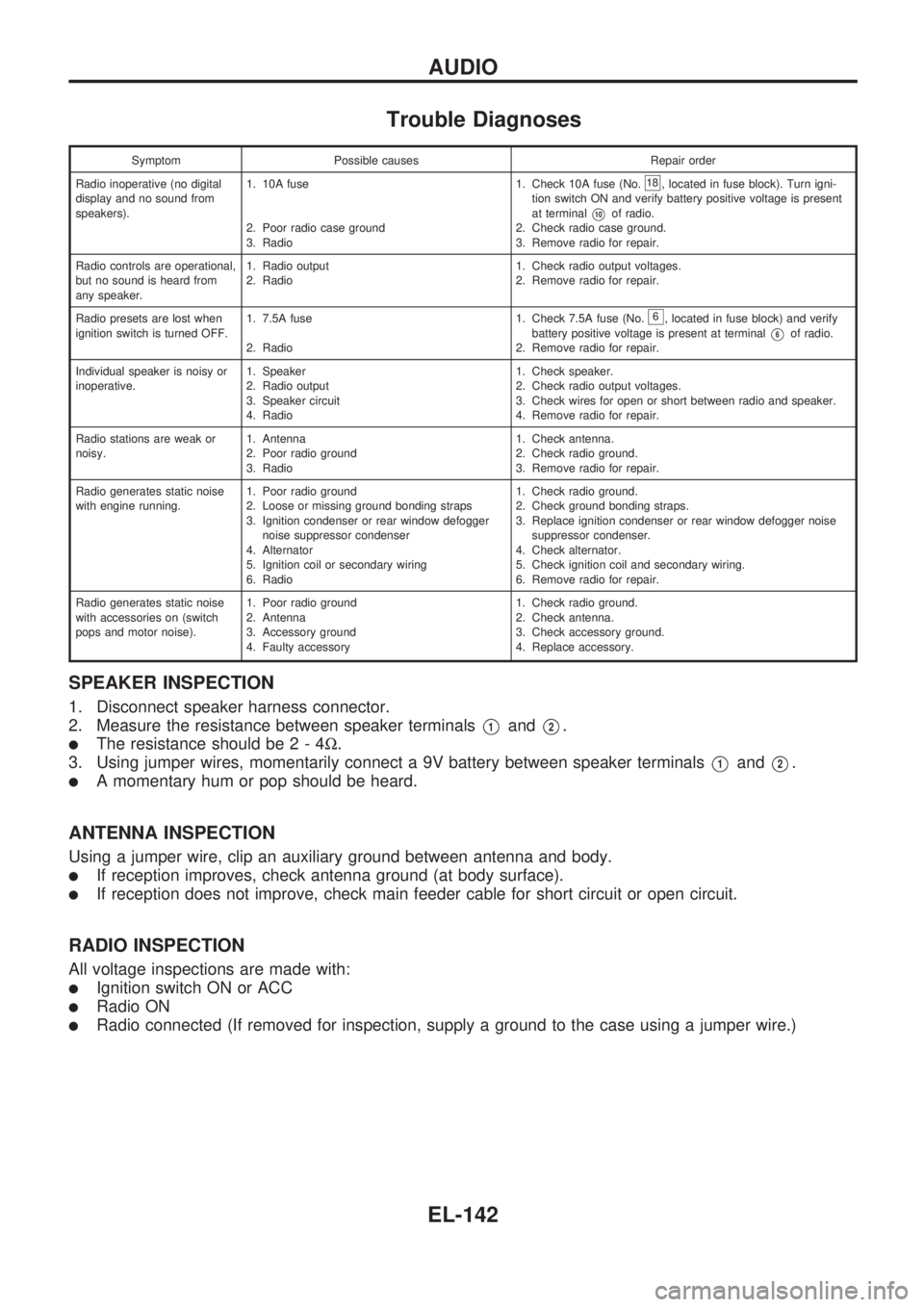
Trouble Diagnoses
Symptom Possible causes Repair order
Radio inoperative (no digital
display and no sound from
speakers).1. 10A fuse
2. Poor radio case ground
3. Radio1. Check 10A fuse (No.
18, located in fuse block). Turn igni-
tion switch ON and verify battery positive voltage is present
at terminal
V10of radio.
2. Check radio case ground.
3. Remove radio for repair.
Radio controls are operational,
but no sound is heard from
any speaker.1. Radio output
2. Radio1. Check radio output voltages.
2. Remove radio for repair.
Radio presets are lost when
ignition switch is turned OFF.1. 7.5A fuse
2. Radio1. Check 7.5A fuse (No.
6, located in fuse block) and verify
battery positive voltage is present at terminal
V6of radio.
2. Remove radio for repair.
Individual speaker is noisy or
inoperative.1. Speaker
2. Radio output
3. Speaker circuit
4. Radio1. Check speaker.
2. Check radio output voltages.
3. Check wires for open or short between radio and speaker.
4. Remove radio for repair.
Radio stations are weak or
noisy.1. Antenna
2. Poor radio ground
3. Radio1. Check antenna.
2. Check radio ground.
3. Remove radio for repair.
Radio generates static noise
with engine running.1. Poor radio ground
2. Loose or missing ground bonding straps
3. Ignition condenser or rear window defogger
noise suppressor condenser
4. Alternator
5. Ignition coil or secondary wiring
6. Radio1. Check radio ground.
2. Check ground bonding straps.
3. Replace ignition condenser or rear window defogger noise
suppressor condenser.
4. Check alternator.
5. Check ignition coil and secondary wiring.
6. Remove radio for repair.
Radio generates static noise
with accessories on (switch
pops and motor noise).1. Poor radio ground
2. Antenna
3. Accessory ground
4. Faulty accessory1. Check radio ground.
2. Check antenna.
3. Check accessory ground.
4. Replace accessory.
SPEAKER INSPECTION
1. Disconnect speaker harness connector.
2. Measure the resistance between speaker terminals
V1andV2.
lThe resistance should be2-4W.
3. Using jumper wires, momentarily connect a 9V battery between speaker terminals
V1andV2.
lA momentary hum or pop should be heard.
ANTENNA INSPECTION
Using a jumper wire, clip an auxiliary ground between antenna and body.
lIf reception improves, check antenna ground (at body surface).
lIf reception does not improve, check main feeder cable for short circuit or open circuit.
RADIO INSPECTION
All voltage inspections are made with:
lIgnition switch ON or ACC
lRadio ON
lRadio connected (If removed for inspection, supply a ground to the case using a jumper wire.)
AUDIO
EL-142
Page 650 of 1659
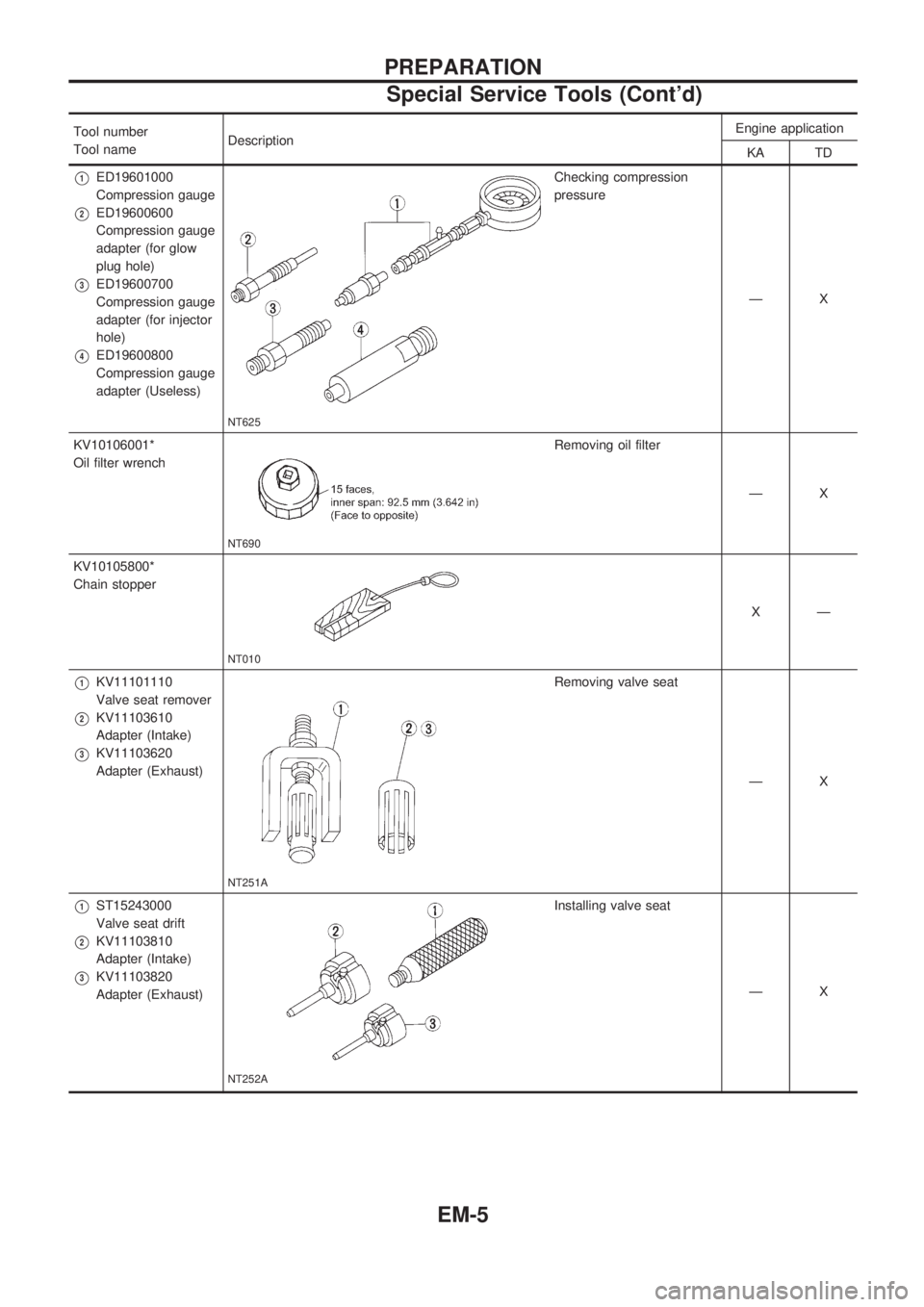
Tool number
Tool nameDescriptionEngine application
KA TD
V1ED19601000
Compression gauge
V2ED19600600
Compression gauge
adapter (for glow
plug hole)
V3ED19600700
Compression gauge
adapter (for injector
hole)
V4ED19600800
Compression gauge
adapter (Useless)
NT625
Checking compression
pressure
ÐX
KV10106001*
Oil filter wrench
NT690
Removing oil filter
ÐX
KV10105800*
Chain stopper
NT010
XÐ
V1KV11101110
Valve seat remover
V2KV11103610
Adapter (Intake)
V3KV11103620
Adapter (Exhaust)
NT251A
Removing valve seat
ÐX
V1ST15243000
Valve seat drift
V2KV11103810
Adapter (Intake)
V3KV11103820
Adapter (Exhaust)
NT252A
Installing valve seat
ÐX
PREPARATION
Special Service Tools (Cont'd)
EM-5
Page 655 of 1659
Measurement of Compression Pressure
1. Warm up engine.
2. Turn ignition switch OFF.
3. Release fuel pressure.
Refer to EC section (``Fuel Pressure Release'', ``BASIC SER-
VICE PROCEDURE'').
4. Remove all spark plugs.
5. Disconnect distributor center cable.
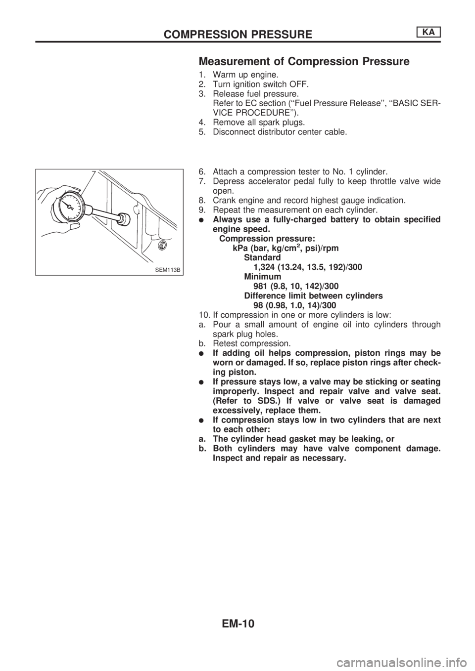
6. Attach a compression tester to No. 1 cylinder.
7. Depress accelerator pedal fully to keep throttle valve wide
open.
8. Crank engine and record highest gauge indication.
9. Repeat the measurement on each cylinder.
lAlways use a fully-charged battery to obtain specified
engine speed.
Compression pressure:
kPa (bar, kg/cm
2, psi)/rpm
Standard
1,324 (13.24, 13.5, 192)/300
Minimum
981 (9.8, 10, 142)/300
Difference limit between cylinders
98 (0.98, 1.0, 14)/300
10. If compression in one or more cylinders is low:
a. Pour a small amount of engine oil into cylinders through
spark plug holes.
b. Retest compression.
lIf adding oil helps compression, piston rings may be
worn or damaged. If so, replace piston rings after check-
ing piston.
lIf pressure stays low, a valve may be sticking or seating
improperly. Inspect and repair valve and valve seat.
(Refer to SDS.) If valve or valve seat is damaged
excessively, replace them.
lIf compression stays low in two cylinders that are next
to each other:
a. The cylinder head gasket may be leaking, or
b. Both cylinders may have valve component damage.
Inspect and repair as necessary.
SEM113B
COMPRESSION PRESSUREKA
EM-10
Page 662 of 1659
Inspection
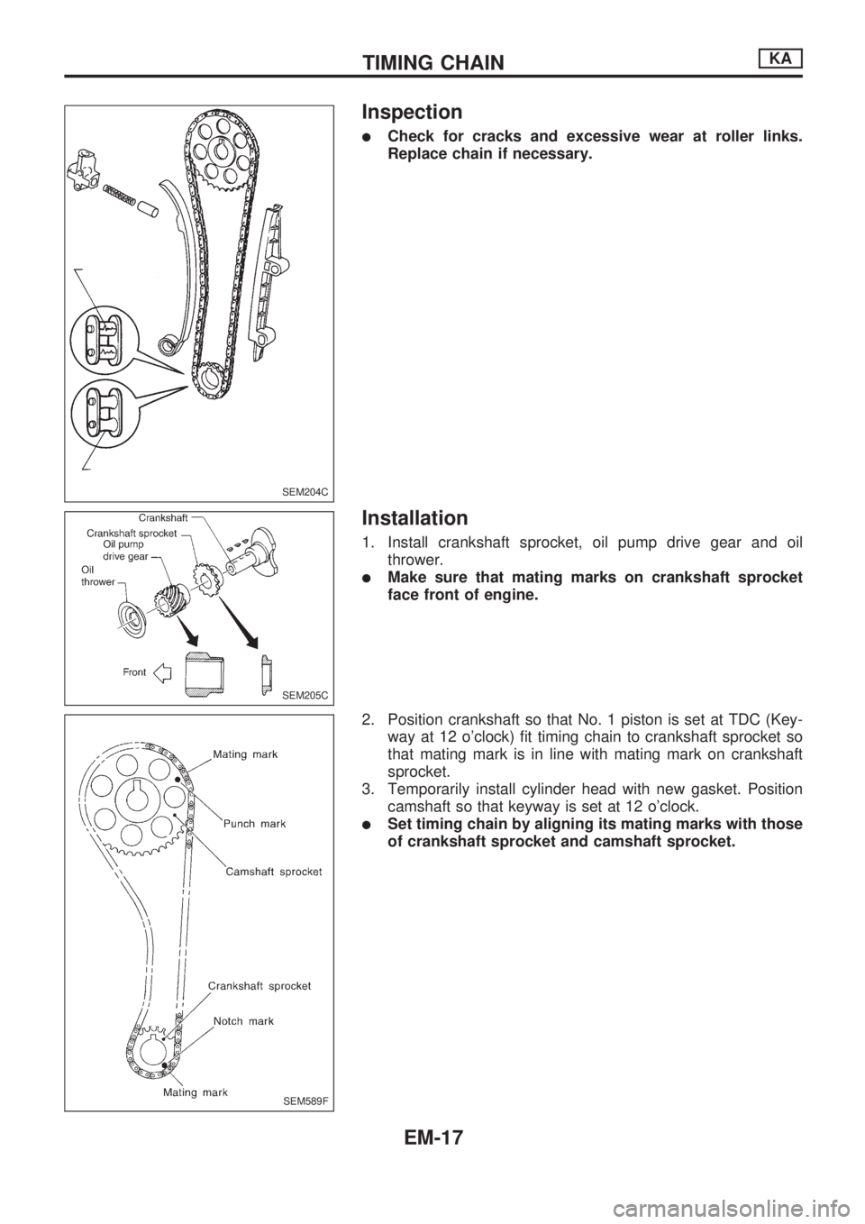
lCheck for cracks and excessive wear at roller links.
Replace chain if necessary.
Installation
1. Install crankshaft sprocket, oil pump drive gear and oil
thrower.
lMake sure that mating marks on crankshaft sprocket
face front of engine.
2. Position crankshaft so that No. 1 piston is set at TDC (Key-
way at 12 o'clock) fit timing chain to crankshaft sprocket so
that mating mark is in line with mating mark on crankshaft
sprocket.
3. Temporarily install cylinder head with new gasket. Position
camshaft so that keyway is set at 12 o'clock.
lSet timing chain by aligning its mating marks with those
of crankshaft sprocket and camshaft sprocket.
SEM204C
SEM205C
SEM589F
TIMING CHAINKA
EM-17
Page 672 of 1659

13. Remove cylinder head.
lLoosen in numerical order.
lA warped or cracked cylinder head could result from
removing in incorrect order.
lLoosen cylinder head bolts in two or three steps.
Disassembly
1. Remove rocker shaft assembly.
a. When loosening bolts, evenly loosen from outside in
sequence.
b. Bolts should be loosened in two or three steps.
2. Remove camshaft.
lBefore removing camshaft, measure camshaft end play.
(Refer to ``Inspection''.)
3. Remove valve components with Tool.
4. Remove valve oil seals. (Refer to ``OIL SEAL REPLACE-
MENT'', EM-22.)
Inspection
CYLINDER HEAD DISTORTION
lClean surface of cylinder head.
lUse a reliable straightedge and feeler gauge to check the
flatness of cylinder head surface.
lCheck along six positions shown in figure.
Head surface flatness: mm (in)
Standard
Less than 0.03 (0.0012)
Limit
0.1 (0.004)
If beyond the specified limit, replace or resurface.
Resurfacing limit:
The limit for cylinder head resurfacing is determined by the
cylinder block resurfacing.
Amount of cylinder head resurfacing is ``A''
Amount of cylinder block resurfacing is ``B''
The maximum limit is as follows:
A+B=0.2mm(0.008 in)
After resurfacing cylinder head, check that camshaft rotates
freely by hand. If resistance is felt, cylinder head must be
replaced.
SEM588F
SEM598F
SEM211EA
AEM257.AEM257
CYLINDER HEADKA
Removal (Cont'd)
EM-27
Page 685 of 1659
PISTON RING SIDE CLEARANCE
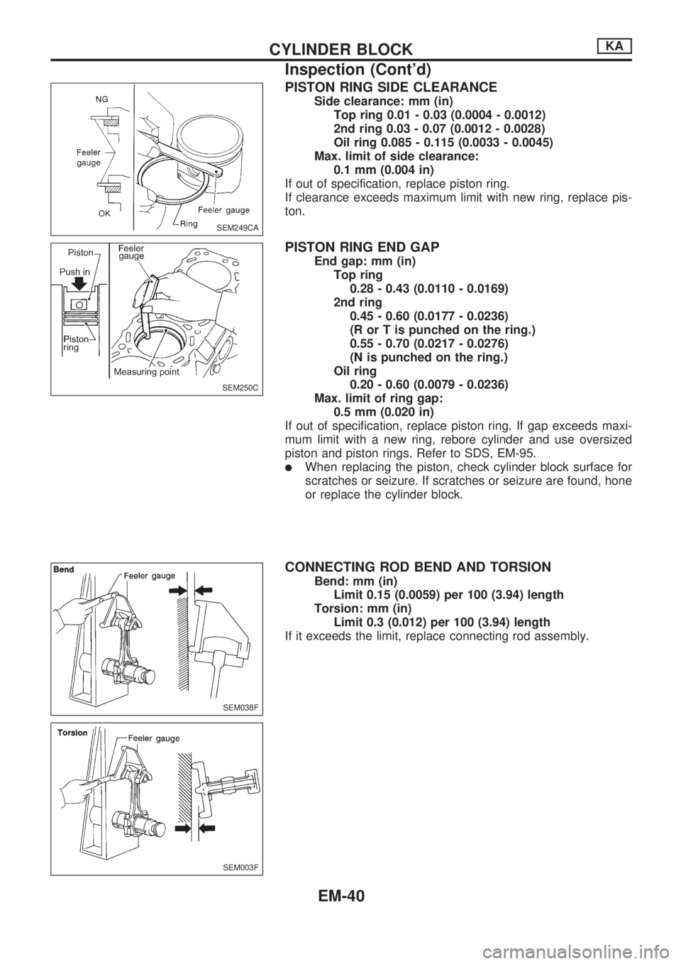
Side clearance: mm (in)
Top ring 0.01 - 0.03 (0.0004 - 0.0012)
2nd ring 0.03 - 0.07 (0.0012 - 0.0028)
Oil ring 0.085 - 0.115 (0.0033 - 0.0045)
Max. limit of side clearance:
0.1 mm (0.004 in)
If out of specification, replace piston ring.
If clearance exceeds maximum limit with new ring, replace pis-
ton.
PISTON RING END GAP
End gap: mm (in)
Top ring
0.28 - 0.43 (0.0110 - 0.0169)
2nd ring
0.45 - 0.60 (0.0177 - 0.0236)
(R or T is punched on the ring.)
0.55 - 0.70 (0.0217 - 0.0276)
(N is punched on the ring.)
Oil ring
0.20 - 0.60 (0.0079 - 0.0236)
Max. limit of ring gap:
0.5 mm (0.020 in)
If out of specification, replace piston ring. If gap exceeds maxi-
mum limit with a new ring, rebore cylinder and use oversized
piston and piston rings. Refer to SDS, EM-95.
lWhen replacing the piston, check cylinder block surface for
scratches or seizure. If scratches or seizure are found, hone
or replace the cylinder block.
CONNECTING ROD BEND AND TORSION
Bend: mm (in)
Limit 0.15 (0.0059) per 100 (3.94) length
Torsion: mm (in)
Limit 0.3 (0.012) per 100 (3.94) length
If it exceeds the limit, replace connecting rod assembly.
SEM249CA
SEM250C
SEM038F
SEM003F
CYLINDER BLOCKKA
Inspection (Cont'd)
EM-40