seats NISSAN PICK-UP 1998 Repair Manual
[x] Cancel search | Manufacturer: NISSAN, Model Year: 1998, Model line: PICK-UP, Model: NISSAN PICK-UP 1998Pages: 1659, PDF Size: 53.39 MB
Page 115 of 1659
Side and Floor Trim
CAUTION:
Wrap the tip of flat-bladed screwdriver with a cloth when removing metal clips from garnishes.
REMOVAL Ð Body side trim
Double cab model
V1Remove front and rear seats. Refer to ``SEAT'' for details, BT-30, 33.
V2Remove front and rear kicking plates.
V3Remove dash side lower finishers.
V4Remove front and rear body side welts.
V5Remove front pillar garnishes.
V6Remove center pillar garnishes.
V7Remove lock pillar garnishes.
Single cab model
V1Remove front seats. Refer to ``SEAT'' for details, BT-30.
V2Remove kicking plates.
V3Remove dash side lower finishers.
V4Remove body side welts.
V5Remove front pillar garnishes.
King cab model
V1Remove body side rear finishers.
V2Remove front seats and jump seats. Refer to ``SEAT'' for details, BT-30, 34.
V3Remove kicking plates.
V4Remove dash side lower finishers.
V5Remove front pillar garnishes.
V6Remove body side finishers.
V7Remove back panel garnish.
V8Remove rear pillar finishers.
V9Remove back panel finisher.
V10Remove body side welts.
V11Remove instrument stay cover lower center and center console. Refer to ``INSTRUMENT PANEL'' for
details, BT-12.
V12Remove accel stopper.
V13Remove rear floor trim.
V14Remove clips and accel stopper, then remove front floor trim.
INTERIOR TRIM
BT-15
Page 121 of 1659
Roof Trim
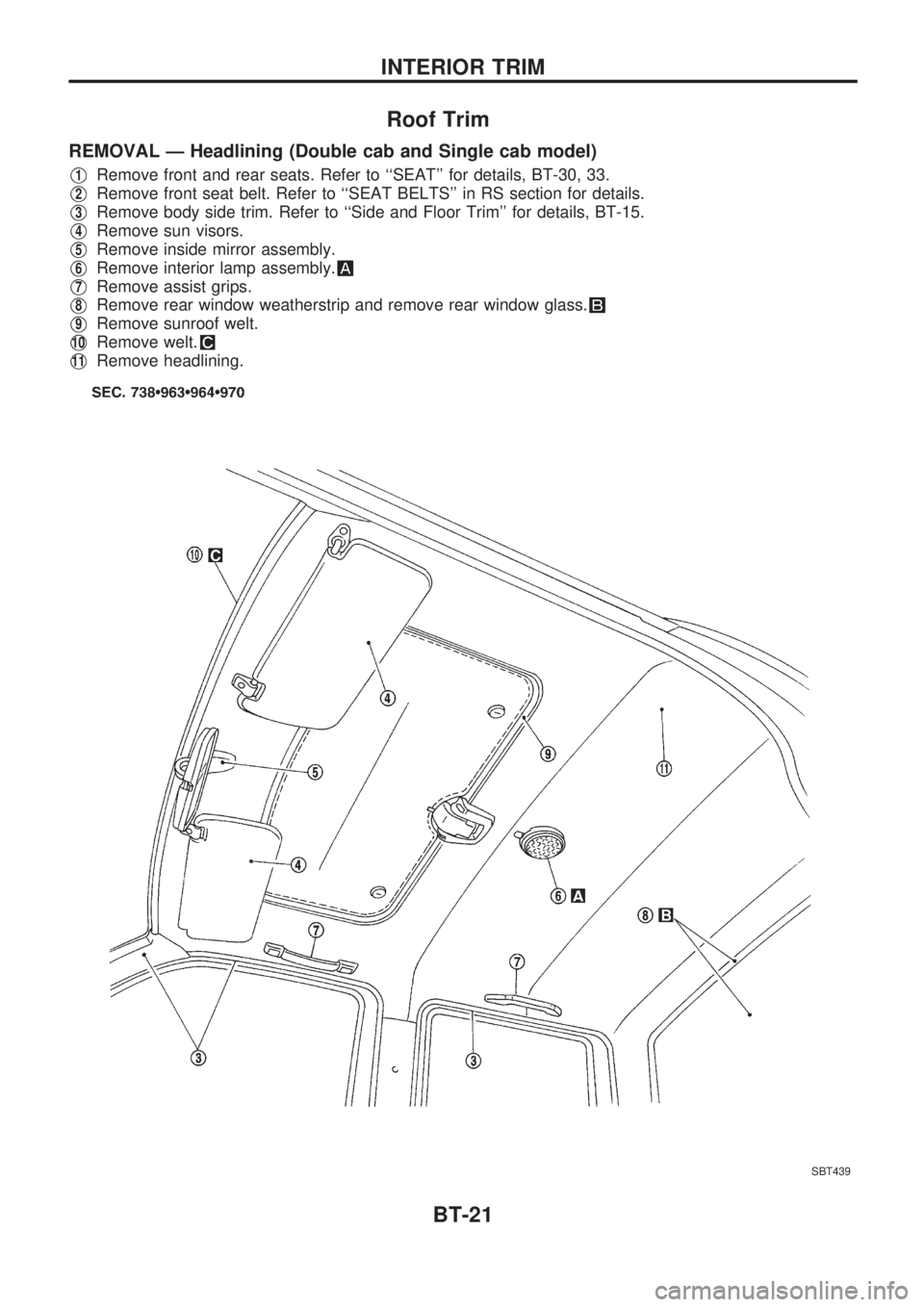
REMOVAL Ð Headlining (Double cab and Single cab model)
V1Remove front and rear seats. Refer to ``SEAT'' for details, BT-30, 33.
V2Remove front seat belt. Refer to ``SEAT BELTS'' in RS section for details.
V3Remove body side trim. Refer to ``Side and Floor Trim'' for details, BT-15.
V4Remove sun visors.
V5Remove inside mirror assembly.
V6Remove interior lamp assembly.
V7Remove assist grips.
V8Remove rear window weatherstrip and remove rear window glass.
V9Remove sunroof welt.
V10Remove welt.
V11Remove headlining.
SBT439
INTERIOR TRIM
BT-21
Page 123 of 1659
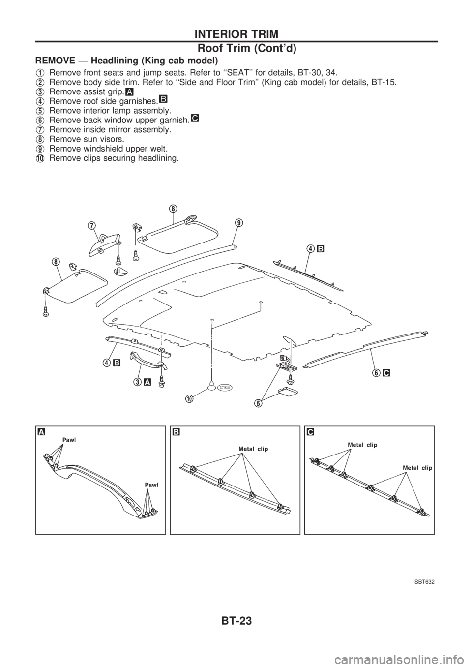
REMOVE Ð Headlining (King cab model)
V1Remove front seats and jump seats. Refer to ``SEAT'' for details, BT-30, 34.
V2Remove body side trim. Refer to ``Side and Floor Trim'' (King cab model) for details, BT-15.
V3Remove assist grip.
V4Remove roof side garnishes.
V5Remove interior lamp assembly.
V6Remove back window upper garnish.
V7Remove inside mirror assembly.
V8Remove sun visors.
V9Remove windshield upper welt.
V10Remove clips securing headlining.
SBT632
INTERIOR TRIM
Roof Trim (Cont'd)
BT-23
Page 676 of 1659
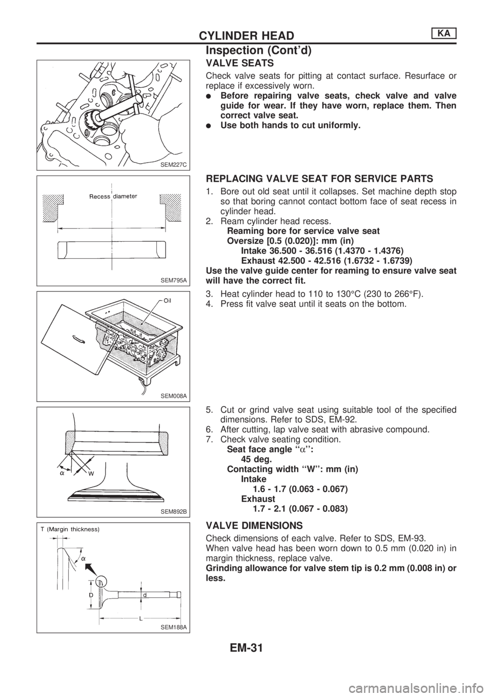
VALVE SEATS
Check valve seats for pitting at contact surface. Resurface or
replace if excessively worn.
lBefore repairing valve seats, check valve and valve
guide for wear. If they have worn, replace them. Then
correct valve seat.
lUse both hands to cut uniformly.
REPLACING VALVE SEAT FOR SERVICE PARTS
1. Bore out old seat until it collapses. Set machine depth stop
so that boring cannot contact bottom face of seat recess in
cylinder head.
2. Ream cylinder head recess.
Reaming bore for service valve seat
Oversize [0.5 (0.020)]: mm (in)
Intake 36.500 - 36.516 (1.4370 - 1.4376)
Exhaust 42.500 - 42.516 (1.6732 - 1.6739)
Use the valve guide center for reaming to ensure valve seat
will have the correct fit.
3. Heat cylinder head to 110 to 130ÉC (230 to 266ÉF).
4. Press fit valve seat until it seats on the bottom.
5. Cut or grind valve seat using suitable tool of the specified
dimensions. Refer to SDS, EM-92.
6. After cutting, lap valve seat with abrasive compound.
7. Check valve seating condition.
Seat face angle ``a'':
45 deg.
Contacting width ``W'': mm (in)
Intake
1.6 - 1.7 (0.063 - 0.067)
Exhaust
1.7 - 2.1 (0.067 - 0.083)
VALVE DIMENSIONS
Check dimensions of each valve. Refer to SDS, EM-93.
When valve head has been worn down to 0.5 mm (0.020 in) in
margin thickness, replace valve.
Grinding allowance for valve stem tip is 0.2 mm (0.008 in) or
less.
SEM227C
SEM795A
SEM008A
SEM892B
SEM188A
CYLINDER HEADKA
Inspection (Cont'd)
EM-31
Page 702 of 1659
![NISSAN PICK-UP 1998 Repair Manual Valve guide inner diameter:
8.000 - 8.015 mm (0.3150 - 0.3156 in)
VALVE GUIDE REPLACEMENT
1. Drive out valve guide with a press [under a 20 kN (2 ton, 2.2
US ton, 2.0 Imp ton) pressure] or hammer, and NISSAN PICK-UP 1998 Repair Manual Valve guide inner diameter:
8.000 - 8.015 mm (0.3150 - 0.3156 in)
VALVE GUIDE REPLACEMENT
1. Drive out valve guide with a press [under a 20 kN (2 ton, 2.2
US ton, 2.0 Imp ton) pressure] or hammer, and](/img/5/57374/w960_57374-701.png)
Valve guide inner diameter:
8.000 - 8.015 mm (0.3150 - 0.3156 in)
VALVE GUIDE REPLACEMENT
1. Drive out valve guide with a press [under a 20 kN (2 ton, 2.2
US ton, 2.0 Imp ton) pressure] or hammer, and suitable tool.
2. Press service valve guide onto cylinder head using suitable
tool until the guide projects out 15.8 to 16.2 mm (0.622 to
0.638 in).
3. Ream valve guide.
Finished size:
8.000 - 8.015 mm (0.3150 - 0.3156 in)
VALVE SEATS
Check valve for any evidence of pitting at valve contact surface,
and reseat or replace if worn out excessively.
lWhen repairing valve seats, check valve and valve guide
for wear beforehand. If worn, replace them. Then correct
valve seat.
lThe cutting should be done with both hands for uniform
cutting.
SEM649B
SEM628B
SEM629BA
SEM630B
SEM024-A
CYLINDER HEADTD
Inspection (Cont'd)
EM-57
Page 703 of 1659
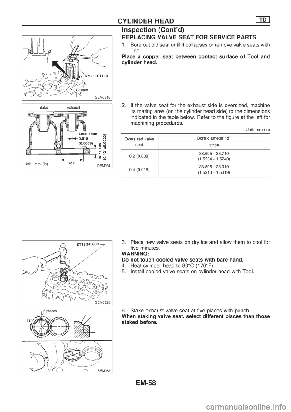
REPLACING VALVE SEAT FOR SERVICE PARTS
1. Bore out old seat until it collapses or remove valve seats with
Tool.
Place a copper seat between contact surface of Tool and
cylinder head.
2. If the valve seat for the exhaust side is oversized, machine
its mating area (on the cylinder head side) to the dimensions
indicated in the table below. Refer to the figure at the left for
machining procedures.
Unit: mm (in)
Oversized valve
seatBore diameter ``d''
TD25
0.2 (0.008)38.695 - 38.710
(1.5234 - 1.5240)
0.4 (0.016)38.895 - 38.910
(1.5313 - 1.5319)
3. Place new valve seats on dry ice and allow them to cool for
five minutes.
WARNING:
Do not touch cooled valve seats with bare hand.
4. Heat cylinder head to 80ÉC (176ÉF).
5. Install cooled valve seats on cylinder head with Tool.
6. Stake exhaust valve seat at five places with punch.
When staking valve seat, select different places than those
staked before.
SEM631B
DEM031
SEM632B
SEM087
CYLINDER HEADTD
Inspection (Cont'd)
EM-58
Page 782 of 1659
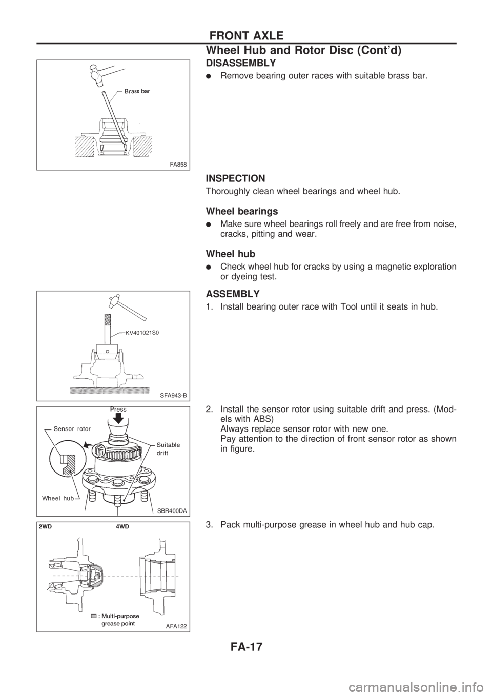
DISASSEMBLY
lRemove bearing outer races with suitable brass bar.
INSPECTION
Thoroughly clean wheel bearings and wheel hub.
Wheel bearings
lMake sure wheel bearings roll freely and are free from noise,
cracks, pitting and wear.
Wheel hub
lCheck wheel hub for cracks by using a magnetic exploration
or dyeing test.
ASSEMBLY
1. Install bearing outer race with Tool until it seats in hub.
2. Install the sensor rotor using suitable drift and press. (Mod-
els with ABS)
Always replace sensor rotor with new one.
Pay attention to the direction of front sensor rotor as shown
in figure.
3. Pack multi-purpose grease in wheel hub and hub cap.
FA858
SFA943-B
SBR400DA
AFA122
FRONT AXLE
Wheel Hub and Rotor Disc (Cont'd)
FA-17
Page 976 of 1659
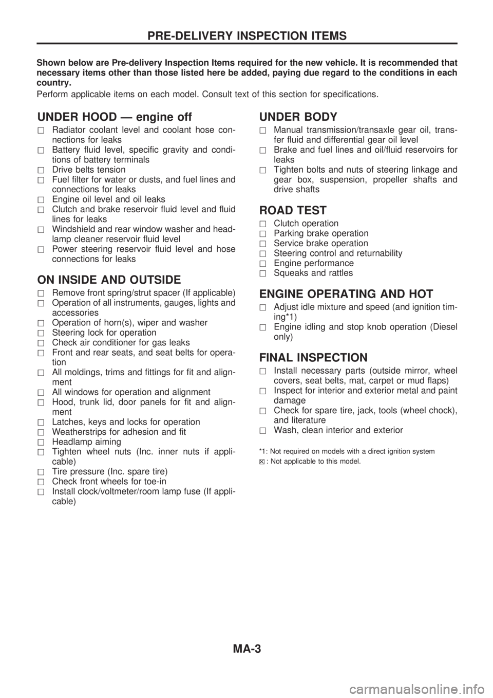
Shown below are Pre-delivery Inspection Items required for the new vehicle. It is recommended that
necessary items other than those listed here be added, paying due regard to the conditions in each
country.
Perform applicable items on each model. Consult text of this section for specifications.
UNDER HOOD Ð engine off
hRadiator coolant level and coolant hose con-
nections for leaks
hBattery fluid level, specific gravity and condi-
tions of battery terminals
hDrive belts tension
hFuel filter for water or dusts, and fuel lines and
connections for leaks
hEngine oil level and oil leaks
hClutch and brake reservoir fluid level and fluid
lines for leaks
hWindshield and rear window washer and head-
lamp cleaner reservoir fluid level
hPower steering reservoir fluid level and hose
connections for leaks
ON INSIDE AND OUTSIDE
hRemove front spring/strut spacer (If applicable)
hOperation of all instruments, gauges, lights and
accessories
hOperation of horn(s), wiper and washer
hSteering lock for operation
hCheck air conditioner for gas leaks
hFront and rear seats, and seat belts for opera-
tion
hAll moldings, trims and fittings for fit and align-
ment
hAll windows for operation and alignment
hHood, trunk lid, door panels for fit and align-
ment
hLatches, keys and locks for operation
hWeatherstrips for adhesion and fit
hHeadlamp aiming
hTighten wheel nuts (Inc. inner nuts if appli-
cable)
hTire pressure (Inc. spare tire)
hCheck front wheels for toe-in
hInstall clock/voltmeter/room lamp fuse (If appli-
cable)
UNDER BODY
hManual transmission/transaxle gear oil, trans-
fer fluid and differential gear oil level
hBrake and fuel lines and oil/fluid reservoirs for
leaks
hTighten bolts and nuts of steering linkage and
gear box, suspension, propeller shafts and
drive shafts
ROAD TEST
hClutch operation
hParking brake operation
hService brake operation
hSteering control and returnability
hEngine performance
hSqueaks and rattles
ENGINE OPERATING AND HOT
hAdjust idle mixture and speed (and ignition tim-
ing*1)
hEngine idling and stop knob operation (Diesel
only)
FINAL INSPECTION
hInstall necessary parts (outside mirror, wheel
covers, seat belts, mat, carpet or mud flaps)
hInspect for interior and exterior metal and paint
damage
hCheck for spare tire, jack, tools (wheel chock),
and literature
hWash, clean interior and exterior
*1: Not required on models with a direct ignition system
h
X: Not applicable to this model.
PRE-DELIVERY INSPECTION ITEMS
MA-3
Page 1584 of 1659
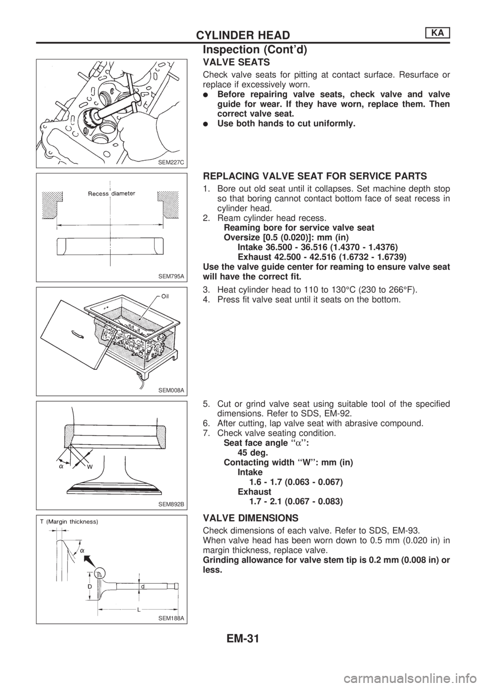
VALVE SEATS
Check valve seats for pitting at contact surface. Resurface or
replace if excessively worn.
lBefore repairing valve seats, check valve and valve
guide for wear. If they have worn, replace them. Then
correct valve seat.
lUse both hands to cut uniformly.
REPLACING VALVE SEAT FOR SERVICE PARTS
1. Bore out old seat until it collapses. Set machine depth stop
so that boring cannot contact bottom face of seat recess in
cylinder head.
2. Ream cylinder head recess.
Reaming bore for service valve seat
Oversize [0.5 (0.020)]: mm (in)
Intake 36.500 - 36.516 (1.4370 - 1.4376)
Exhaust 42.500 - 42.516 (1.6732 - 1.6739)
Use the valve guide center for reaming to ensure valve seat
will have the correct fit.
3. Heat cylinder head to 110 to 130ÉC (230 to 266ÉF).
4. Press fit valve seat until it seats on the bottom.
5. Cut or grind valve seat using suitable tool of the specified
dimensions. Refer to SDS, EM-92.
6. After cutting, lap valve seat with abrasive compound.
7. Check valve seating condition.
Seat face angle ``a'':
45 deg.
Contacting width ``W'': mm (in)
Intake
1.6 - 1.7 (0.063 - 0.067)
Exhaust
1.7 - 2.1 (0.067 - 0.083)
VALVE DIMENSIONS
Check dimensions of each valve. Refer to SDS, EM-93.
When valve head has been worn down to 0.5 mm (0.020 in) in
margin thickness, replace valve.
Grinding allowance for valve stem tip is 0.2 mm (0.008 in) or
less.
SEM227C
SEM795A
SEM008A
SEM892B
SEM188A
CYLINDER HEADKA
Inspection (Cont'd)
EM-31
Page 1610 of 1659
![NISSAN PICK-UP 1998 Repair Manual Valve guide inner diameter:
8.000 - 8.015 mm (0.3150 - 0.3156 in)
VALVE GUIDE REPLACEMENT
1. Drive out valve guide with a press [under a 20 kN (2 ton, 2.2
US ton, 2.0 Imp ton) pressure] or hammer, and NISSAN PICK-UP 1998 Repair Manual Valve guide inner diameter:
8.000 - 8.015 mm (0.3150 - 0.3156 in)
VALVE GUIDE REPLACEMENT
1. Drive out valve guide with a press [under a 20 kN (2 ton, 2.2
US ton, 2.0 Imp ton) pressure] or hammer, and](/img/5/57374/w960_57374-1609.png)
Valve guide inner diameter:
8.000 - 8.015 mm (0.3150 - 0.3156 in)
VALVE GUIDE REPLACEMENT
1. Drive out valve guide with a press [under a 20 kN (2 ton, 2.2
US ton, 2.0 Imp ton) pressure] or hammer, and suitable tool.
2. Press service valve guide onto cylinder head using suitable
tool until the guide projects out 15.8 to 16.2 mm (0.622 to
0.638 in).
3. Ream valve guide.
Finished size:
8.000 - 8.015 mm (0.3150 - 0.3156 in)
VALVE SEATS
Check valve for any evidence of pitting at valve contact surface,
and reseat or replace if worn out excessively.
lWhen repairing valve seats, check valve and valve guide
for wear beforehand. If worn, replace them. Then correct
valve seat.
lThe cutting should be done with both hands for uniform
cutting.
SEM649B
SEM628B
SEM629BA
SEM630B
SEM024-A
CYLINDER HEADTD
Inspection (Cont'd)
EM-57