suspension NISSAN PICK-UP 1998 Service Manual
[x] Cancel search | Manufacturer: NISSAN, Model Year: 1998, Model line: PICK-UP, Model: NISSAN PICK-UP 1998Pages: 1659, PDF Size: 53.39 MB
Page 1221 of 1659

General Specifications
Suspension typeRigid axle with semi-elliptic leaf
spring
Shock absorber type Double-acting hydraulic
Inspection and Adjustment
WHEEL BEARING
Ð 2WD and 4WD models without ABS
Total end play mm (in) 0.02 - 0.15 (0.0008 - 0.0059)
Available rear axle case end
shimsThickness
mm (in)Part number
0.05 (0.0020)
0.07 (0.0028)
0.10 (0.0039)
0.15 (0.0059)
0.20 (0.0079)
0.50 (0.0197)
1.00 (0.0394)43086-P0110
43087-P0110
43088-P0110
43086-B9500
43089-P0110
43090-P0110
43036-01G00
WHEEL BEARING
Ð 4WD models with ABS
Total end play mm (in) 0 (0)
Wheel bearing preload at bearing
cage bolt N (kg, lb)6.9 - 48.1 (0.7 - 4.9, 1.5 - 10.8)
SERVICE DATA AND SPECIFICATIONS (SDS)
RA-15
Page 1228 of 1659
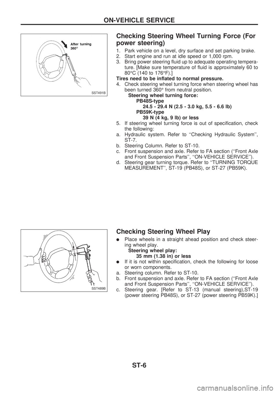
Checking Steering Wheel Turning Force (For
power steering)
1. Park vehicle on a level, dry surface and set parking brake.
2. Start engine and run at idle speed or 1,000 rpm.
3. Bring power steering fluid up to adequate operating tempera-
ture. [Make sure temperature of fluid is approximately 60 to
80ÉC (140 to 176ÉF).]
Tires need to be inflated to normal pressure.
4. Check steering wheel turning force when steering wheel has
been turned 360É from neutral position.
Steering wheel turning force:
PB48S-type
24.5 - 29.4 N (2.5 - 3.0 kg, 5.5 - 6.6 lb)
PB59K-type
39 N (4 kg, 9 lb) or less
5. If steering wheel turning force is out of specification, check
the following:
a. Hydraulic system. Refer to ``Checking Hydraulic System'',
ST-7.
b. Steering Column. Refer to ST-10.
c. Front suspension and axle. Refer to FA section (``Front Axle
and Front Suspension Parts'', ``ON-VEHICLE SERVICE'').
d. Steering gear turning torque. Refer to ``TURNING TORQUE
MEASUREMENT'', ST-19 (PB48S), or ST-27 (PB59K).
Checking Steering Wheel Play
lPlace wheels in a straight ahead position and check steer-
ing wheel play.
Steering wheel play:
35 mm (1.38 in) or less
lIf it is not within specification, check the following for loose
or worn components.
a. Steering column. Refer to ST-10.
b. Front suspension and axle. Refer to FA section (``Front Axle
and Front Suspension Parts'', ``ON-VEHICLE SERVICE'').
c. Steering gear. [Refer to ST-13 (manual steering),ST-19
(power steering PB48S), or ST-27 (power steering PB59K).]
SST491B
SST489B
ON-VEHICLE SERVICE
ST-6
Page 1271 of 1659

Removal
1. Drain oil from transfer and transmission.
2. Remove front and rear propeller shaft. Refer to PD section
(``Removal and Installation'', ``PROPELLER SHAFT'').
Insert plug into rear oil seal after removing propeller shaft.
lBe careful not to damage spline, sleeve yoke and rear oil
seal, when removing propeller shaft.
3. Remove torsion bar spring. Refer to FA section (``Torsion Bar
Spring'', ``FRONT SUSPENSION''). Then remove second
crossmember.
4. Disconnect 4WD and neutral position switches.
5. Remove transfer control lever from transfer outer shift lever.
6. Separate transfer from transmission.
WARNING:
Support transfer while removing it.
Installation
lApply recommended sealant to mating surface to transmis-
sion.
Recommended sealant:
Nissan genuine part KP610-00250, Three Bond
1215 or equivalent
lTighten bolts securing transfer.
Bolt No.Tightening torque
(kg-m, ft-lb)!mm (in)
V131 - 41 (3.2 - 4.2, 23 - 30) 45 (1.77)
V231 - 41 (3.2 - 4.2, 23 - 30) 60 (2.36)
SMT142D
SMT863C
SMT495A
SMT496A
REMOVAL AND INSTALLATION
TF-6
Page 1564 of 1659
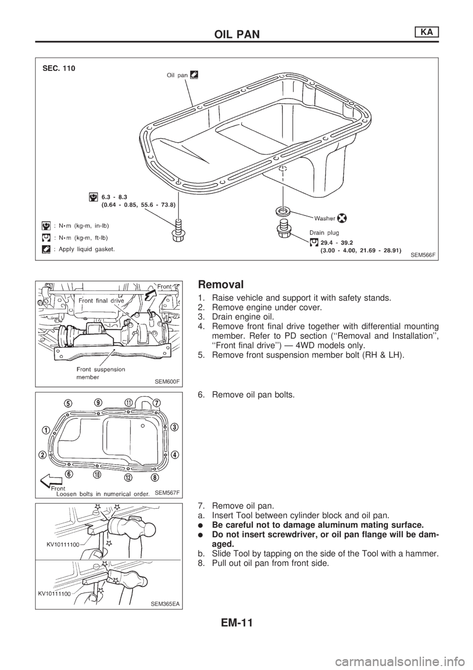
Removal
1. Raise vehicle and support it with safety stands.
2. Remove engine under cover.
3. Drain engine oil.
4. Remove front final drive together with differential mounting
member. Refer to PD section (``Removal and Installation'',
``Front final drive'') Ð 4WD models only.
5. Remove front suspension member bolt (RH & LH).
6. Remove oil pan bolts.
7. Remove oil pan.
a. Insert Tool between cylinder block and oil pan.
lBe careful not to damage aluminum mating surface.
lDo not insert screwdriver, or oil pan flange will be dam-
aged.
b. Slide Tool by tapping on the side of the Tool with a hammer.
8. Pull out oil pan from front side.
SEM566F
SEM600F
SEM567F
SEM365EA
OIL PANKA
EM-11
Page 1605 of 1659
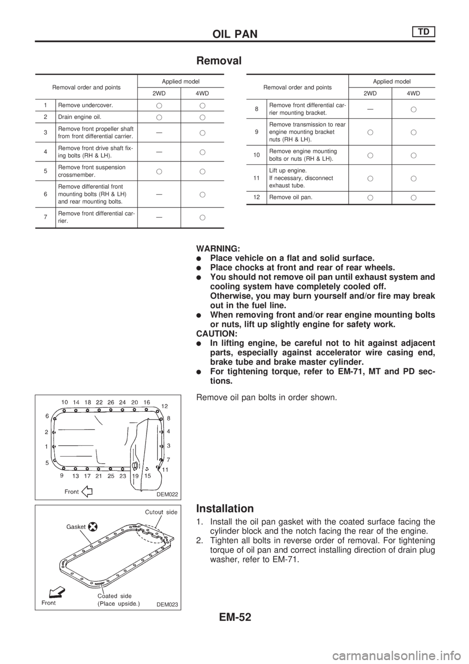
Removal
Removal order and pointsApplied model
2WD 4WD
1 Remove undercover.jj
2 Drain engine oil.jj
3Remove front propeller shaft
from front differential carrier.Ðj
4Remove front drive shaft fix-
ing bolts (RH & LH).Ðj
5Remove front suspension
crossmember.jj
6Remove differential front
mounting bolts (RH & LH)
and rear mounting bolts.Ðj
7Remove front differential car-
rier.ÐjRemoval order and pointsApplied model
2WD 4WD
8Remove front differential car-
rier mounting bracket.Ðj
9Remove transmission to rear
engine mounting bracket
nuts (RH & LH).jj
10Remove engine mounting
bolts or nuts (RH & LH).jj
11Lift up engine.
If necessary, disconnect
exhaust tube.jj
12 Remove oil pan.jj
WARNING:
lPlace vehicle on a flat and solid surface.
lPlace chocks at front and rear of rear wheels.
lYou should not remove oil pan until exhaust system and
cooling system have completely cooled off.
Otherwise, you may burn yourself and/or fire may break
out in the fuel line.
lWhen removing front and/or rear engine mounting bolts
or nuts, lift up slightly engine for safety work.
CAUTION:
lIn lifting engine, be careful not to hit against adjacent
parts, especially against accelerator wire casing end,
brake tube and brake master cylinder.
lFor tightening torque, refer to EM-71, MT and PD sec-
tions.
Remove oil pan bolts in order shown.
Installation
1. Install the oil pan gasket with the coated surface facing the
cylinder block and the notch facing the rear of the engine.
2. Tighten all bolts in reverse order of removal. For tightening
torque of oil pan and correct installing direction of drain plug
washer, refer to EM-71.
DEM022
DEM023
OIL PANTD
EM-52