compression ratio NISSAN PICK-UP 1998 Repair Manual
[x] Cancel search | Manufacturer: NISSAN, Model Year: 1998, Model line: PICK-UP, Model: NISSAN PICK-UP 1998Pages: 1659, PDF Size: 53.39 MB
Page 177 of 1659
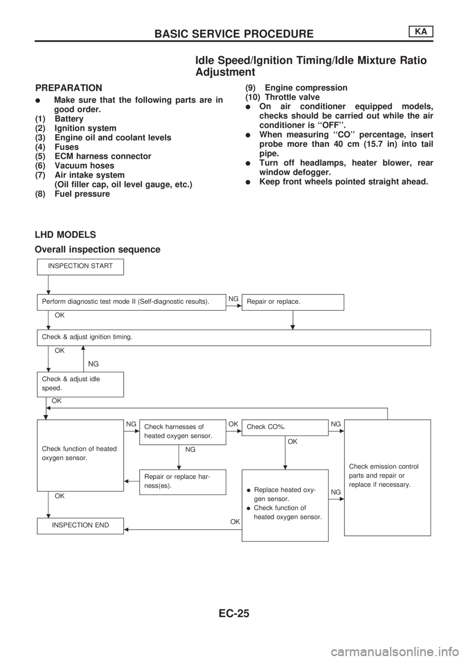
Idle Speed/Ignition Timing/Idle Mixture Ratio
Adjustment
PREPARATION
lMake sure that the following parts are in
good order.
(1) Battery
(2) Ignition system
(3) Engine oil and coolant levels
(4) Fuses
(5) ECM harness connector
(6) Vacuum hoses
(7) Air intake system
(Oil filler cap, oil level gauge, etc.)
(8) Fuel pressure(9) Engine compression
(10) Throttle valvelOn air conditioner equipped models,
checks should be carried out while the air
conditioner is ``OFF''.
lWhen measuring ``CO'' percentage, insert
probe more than 40 cm (15.7 in) into tail
pipe.
lTurn off headlamps, heater blower, rear
window defogger.
lKeep front wheels pointed straight ahead.
LHD MODELS
Overall inspection sequence
INSPECTION START
Perform diagnostic test mode II (Self-diagnostic results).
OK
cNG
Repair or replace.
.
Check & adjust ignition timing.
OKm
NG
Check & adjust idle
speed.
.
OKb
Check function of heated
oxygen sensor.
OK
cNG
Check harnesses of
heated oxygen sensor.
NG
cOK
Check CO%.
OK
.
cNG
Check emission control
parts and repair or
replace if necessary.
bRepair or replace har-
ness(es).
lReplace heated oxy-
gen sensor.
lCheck function of
heated oxygen sensor.
cNG
INSPECTION END
bOK
.
.
.
.
.
BASIC SERVICE PROCEDUREKA
EC-25
Page 202 of 1659
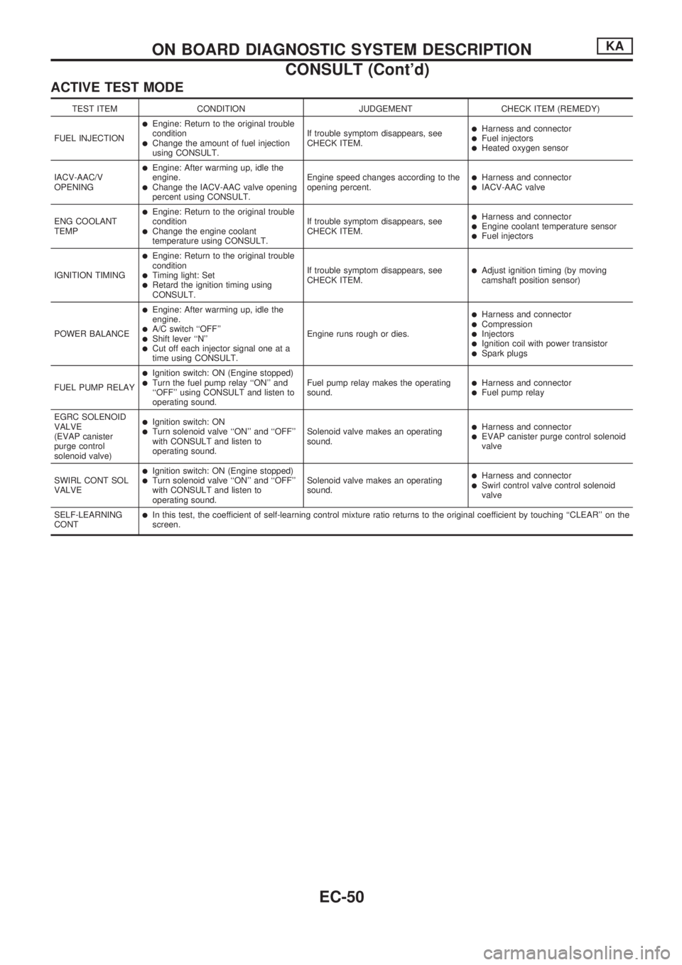
ACTIVE TEST MODE
TEST ITEM CONDITION JUDGEMENT CHECK ITEM (REMEDY)
FUEL INJECTION
lEngine: Return to the original trouble
condition
lChange the amount of fuel injection
using CONSULT.If trouble symptom disappears, see
CHECK ITEM.
lHarness and connectorlFuel injectorslHeated oxygen sensor
IACV-AAC/V
OPENING
lEngine: After warming up, idle the
engine.
lChange the IACV-AAC valve opening
percent using CONSULT.Engine speed changes according to the
opening percent.lHarness and connectorlIACV-AAC valve
ENG COOLANT
TEMP
lEngine: Return to the original trouble
condition
lChange the engine coolant
temperature using CONSULT.If trouble symptom disappears, see
CHECK ITEM.
lHarness and connectorlEngine coolant temperature sensorlFuel injectors
IGNITION TIMING
lEngine: Return to the original trouble
condition
lTiming light: SetlRetard the ignition timing using
CONSULT.If trouble symptom disappears, see
CHECK ITEM.
lAdjust ignition timing (by moving
camshaft position sensor)
POWER BALANCE
lEngine: After warming up, idle the
engine.
lA/C switch ``OFF''lShift lever ``N''lCut off each injector signal one at a
time using CONSULT.Engine runs rough or dies.
lHarness and connectorlCompressionlInjectorslIgnition coil with power transistorlSpark plugs
FUEL PUMP RELAY
lIgnition switch: ON (Engine stopped)lTurn the fuel pump relay ``ON'' and
``OFF'' using CONSULT and listen to
operating sound.Fuel pump relay makes the operating
sound.lHarness and connectorlFuel pump relay
EGRC SOLENOID
VALVE
(EVAP canister
purge control
solenoid valve)
lIgnition switch: ONlTurn solenoid valve ``ON'' and ``OFF''
with CONSULT and listen to
operating sound.Solenoid valve makes an operating
sound.lHarness and connectorlEVAP canister purge control solenoid
valve
SWIRL CONT SOL
VALVE
lIgnition switch: ON (Engine stopped)lTurn solenoid valve ``ON'' and ``OFF''
with CONSULT and listen to
operating sound.Solenoid valve makes an operating
sound.lHarness and connectorlSwirl control valve control solenoid
valve
SELF-LEARNING
CONT
lIn this test, the coefficient of self-learning control mixture ratio returns to the original coefficient by touching ``CLEAR'' on the
screen.
ON BOARD DIAGNOSTIC SYSTEM DESCRIPTIONKA
CONSULT (Cont'd)
EC-50
Page 204 of 1659
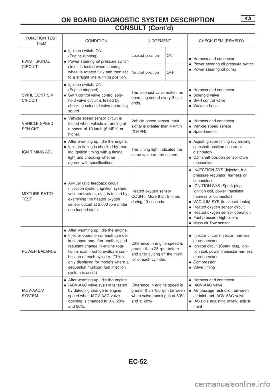
FUNCTION TEST
ITEMCONDITION JUDGEMENT CHECK ITEM (REMEDY)
PW/ST SIGNAL
CIRCUIT
lIgnition switch: ON
(Engine running)
lPower steering oil pressure switch
circuit is tested when steering
wheel is rotated fully and then set
to a straight line running position.Locked position ONlHarness and connector
lPower steering oil pressure switch
lPower steering oil pump
Neutral position OFF
SWRL CONT S/V
CIRCUIT
lIgnition switch: ON
(Engine stopped)
lSwirl control valve control sole-
noid valve circuit is tested by
checking solenoid valve operating
sound.The solenoid valve makes an
operating sound every 3 sec-
onds.
lHarness and connector
lSolenoid valve
lSwirl control valve
lVacuum hose
VEHICLE SPEED
SEN CKT
lVehicle speed sensor circuit is
tested when vehicle is running at
a speed of 10 km/h (6 MPH) or
higher.Vehicle speed sensor input
signal is greater than 4 km/h
(2 MPH).lHarness and connector
lVehicle speed sensor
lSpeedometer
IGN TIMING ADJ
lAfter warming up, idle the engine.
lIgnition timing is checked by read-
ing ignition timing with a timing
light and checking whether it
agrees with specifications.The timing light indicates the
same value on the screen.
lAdjust ignition timing (by moving
camshaft position sensor or
distributor)
lCamshaft position sensor drive
mechanism
MIXTURE RATIO
TEST
lAir-fuel ratio feedback circuit
(injection system, ignition system,
vacuum system, etc.) is tested by
examining the heated oxygen
sensor output at 2,000 rpm under
non-loaded state.Heated oxygen sensor
COUNT: More than 5 times
during 10 seconds
lINJECTION SYS (Injector, fuel
pressure regulator, harness or
connector)
lIGNITION SYS (Spark plug,
ignition coil, power transistor
harness or connector)
lVACUUM SYS (Intake air leaks)
lHeated oxygen sensor circuit
lHeated oxygen sensor operation
lFuel pressure high or low
lMass air flow sensor
POWER BALANCE
lAfter warming up, idle the engine.
lInjector operation of each cylinder
is stopped one after another, and
resultant change in engine rota-
tion is examined to evaluate com-
bustion of each cylinder. (This is
only displayed for models where a
sequential multiport fuel injection
system is used.)Difference in engine speed is
greater than 25 rpm before
and after cutting off the injec-
tor of each cylinder.lInjector circuit (Injector, harness
or connector)
lIgnition circuit (Spark plug, igni-
tion coil, power transistor harness
or connector)
lCompression
lValve timing
IACV-AAC/V
SYSTEM
lAfter warming up, idle the engine.
lIACV-AAC valve system is tested
by detecting change in engine
speed when IACV-AAC valve
opening is changed to 0%, 20%
and 80%.Difference in engine speed is
greater than 150 rpm between
when valve opening is at 80%
and at 20%.
lHarness and connector
lIACV-AAC valve
lAir passage restriction between
air inlet and IACV-AAC valve
lIAS (Idle adjusting screw) adjust-
ment
ON BOARD DIAGNOSTIC SYSTEM DESCRIPTIONKA
CONSULT (Cont'd)
EC-52
Page 644 of 1659
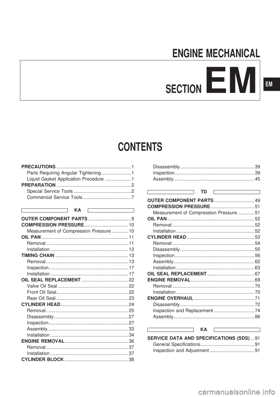
ENGINE MECHANICAL
SECTION
EM
CONTENTS
PRECAUTIONS......................................................... 1
Parts Requiring Angular Tightening....................... 1
Liquid Gasket Application Procedure .................... 1
PREPARATION......................................................... 2
Special Service Tools ............................................ 2
Commercial Service Tools ..................................... 7
KA
OUTER COMPONENT PARTS................................. 9
COMPRESSION PRESSURE.................................. 10
Measurement of Compression Pressure ............. 10
OIL PAN................................................................... 11
Removal ............................................................... 11
Installation ............................................................ 12
TIMING CHAIN........................................................ 13
Removal ............................................................... 13
Inspection ............................................................. 17
Installation ............................................................ 17
OIL SEAL REPLACEMENT.................................... 22
Valve Oil Seal ...................................................... 22
Front Oil Seal ....................................................... 22
Rear Oil Seal ....................................................... 23
CYLINDER HEAD.................................................... 24
Removal ............................................................... 25
Disassembly ......................................................... 27
Inspection ............................................................. 27
Assembly.............................................................. 33
Installation ............................................................ 34
ENGINE REMOVAL................................................. 36
Removal ............................................................... 37
Installation ............................................................ 37
CYLINDER BLOCK................................................. 38Disassembly ......................................................... 39
Inspection ............................................................. 39
Assembly.............................................................. 45
TD
OUTER COMPONENT PARTS............................... 49
COMPRESSION PRESSURE.................................. 51
Measurement of Compression Pressure ............. 51
OIL PAN................................................................... 52
Removal ............................................................... 52
Installation ............................................................ 52
CYLINDER HEAD.................................................... 53
Removal ............................................................... 54
Disassembly ......................................................... 55
Inspection ............................................................. 56
Assembly.............................................................. 62
Installation ............................................................ 63
OIL SEAL REPLACEMENT.................................... 67
ENGINE REMOVAL................................................. 69
Removal ............................................................... 70
Installation ............................................................ 70
ENGINE OVERHAUL.............................................. 71
Disassembly ......................................................... 72
Inspection and Replacement ............................... 74
Assembly.............................................................. 86
KA
SERVICE DATA AND SPECIFICATIONS (SDS)... 91
General Specifications ......................................... 91
Inspection and Adjustment .................................. 91
EM
Page 649 of 1659
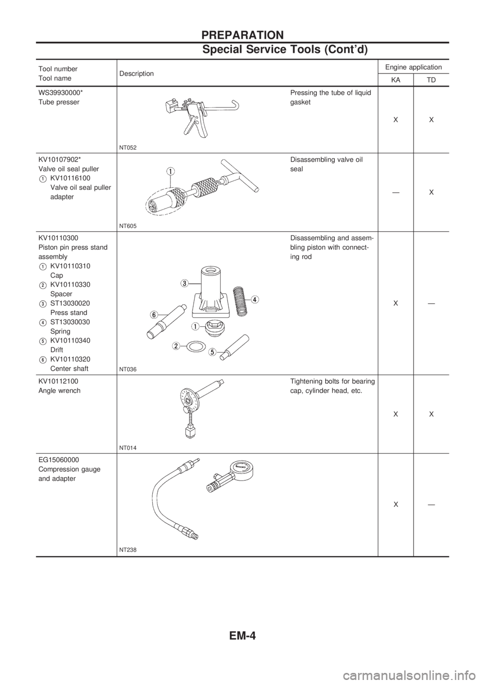
Tool number
Tool nameDescriptionEngine application
KA TD
WS39930000*
Tube presser
NT052
Pressing the tube of liquid
gasket
XX
KV10107902*
Valve oil seal puller
V1KV10116100
Valve oil seal puller
adapter
NT605
Disassembling valve oil
seal
ÐX
KV10110300
Piston pin press stand
assembly
V1KV10110310
Cap
V2KV10110330
Spacer
V3ST13030020
Press stand
V4ST13030030
Spring
V5KV10110340
Drift
V6KV10110320
Center shaft
NT036
Disassembling and assem-
bling piston with connect-
ing rod
XÐ
KV10112100
Angle wrench
NT014
Tightening bolts for bearing
cap, cylinder head, etc.
XX
EG15060000
Compression gauge
and adapter
NT238
XÐ
PREPARATION
Special Service Tools (Cont'd)
EM-4
Page 650 of 1659
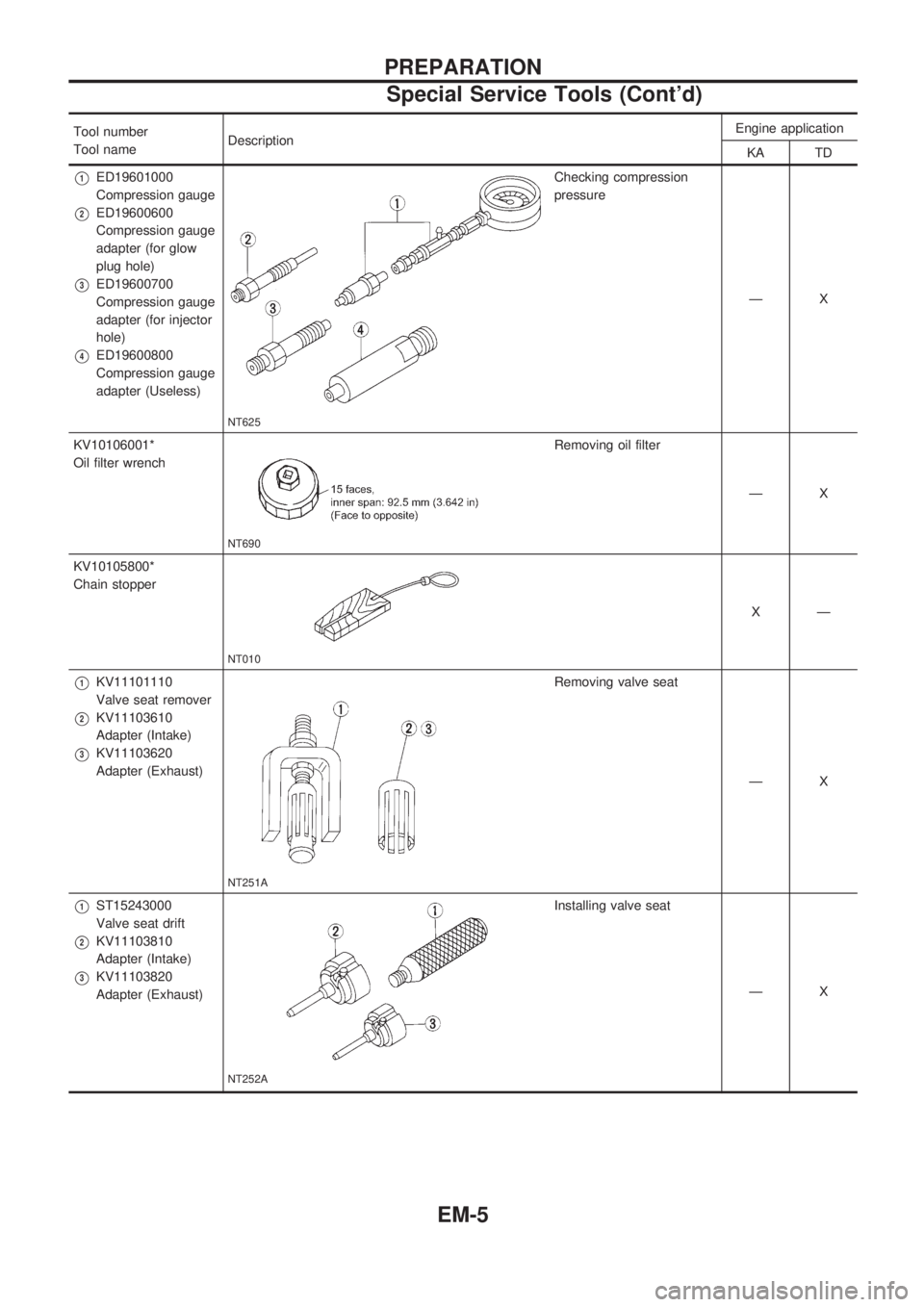
Tool number
Tool nameDescriptionEngine application
KA TD
V1ED19601000
Compression gauge
V2ED19600600
Compression gauge
adapter (for glow
plug hole)
V3ED19600700
Compression gauge
adapter (for injector
hole)
V4ED19600800
Compression gauge
adapter (Useless)
NT625
Checking compression
pressure
ÐX
KV10106001*
Oil filter wrench
NT690
Removing oil filter
ÐX
KV10105800*
Chain stopper
NT010
XÐ
V1KV11101110
Valve seat remover
V2KV11103610
Adapter (Intake)
V3KV11103620
Adapter (Exhaust)
NT251A
Removing valve seat
ÐX
V1ST15243000
Valve seat drift
V2KV11103810
Adapter (Intake)
V3KV11103820
Adapter (Exhaust)
NT252A
Installing valve seat
ÐX
PREPARATION
Special Service Tools (Cont'd)
EM-5
Page 736 of 1659
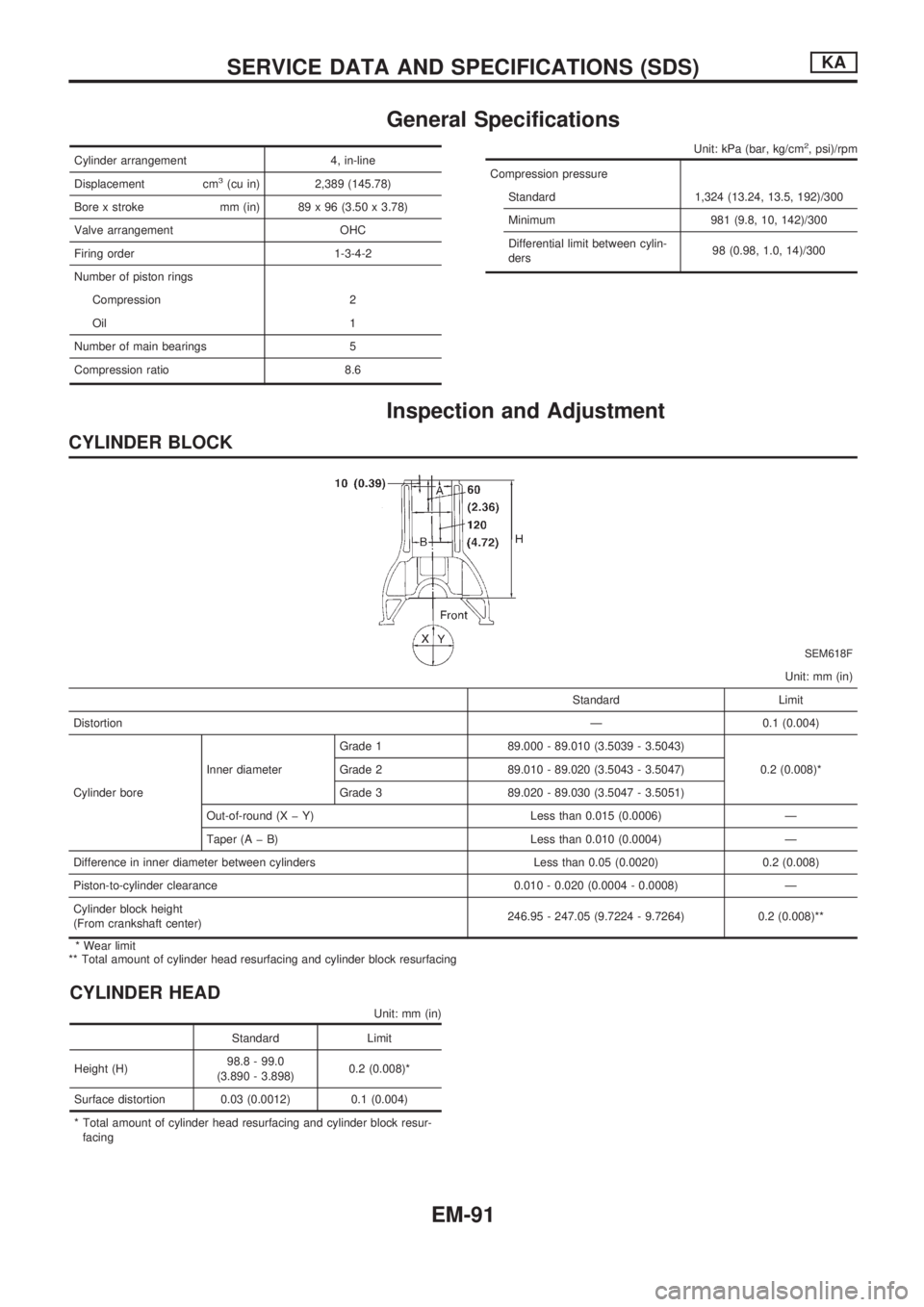
General Specifications
Cylinder arrangement 4, in-line
Displacement cm
3(cu in) 2,389 (145.78)
Bore x stroke mm (in) 89 x 96 (3.50 x 3.78)
Valve arrangement OHC
Firing order 1-3-4-2
Number of piston rings
Compression 2
Oil 1
Number of main bearings 5
Compression ratio 8.6
Unit: kPa (bar, kg/cm2, psi)/rpm
Compression pressure
Standard 1,324 (13.24, 13.5, 192)/300
Minimum 981 (9.8, 10, 142)/300
Differential limit between cylin-
ders98 (0.98, 1.0, 14)/300
Inspection and Adjustment
CYLINDER BLOCK
SEM618F
Unit: mm (in)
Standard Limit
DistortionÐ 0.1 (0.004)
Cylinder boreInner diameterGrade 1 89.000 - 89.010 (3.5039 - 3.5043)
0.2 (0.008)* Grade 2 89.010 - 89.020 (3.5043 - 3.5047)
Grade 3 89.020 - 89.030 (3.5047 - 3.5051)
Out-of-round (X þ Y) Less than 0.015 (0.0006) Ð
Taper (A þ B) Less than 0.010 (0.0004) Ð
Difference in inner diameter between cylinders Less than 0.05 (0.0020) 0.2 (0.008)
Piston-to-cylinder clearance 0.010 - 0.020 (0.0004 - 0.0008) Ð
Cylinder block height
(From crankshaft center)246.95 - 247.05 (9.7224 - 9.7264) 0.2 (0.008)**
* Wear limit
** Total amount of cylinder head resurfacing and cylinder block resurfacing
CYLINDER HEAD
Unit: mm (in)
Standard Limit
Height (H)98.8 - 99.0
(3.890 - 3.898)0.2 (0.008)*
Surface distortion 0.03 (0.0012) 0.1 (0.004)
* Total amount of cylinder head resurfacing and cylinder block resur-
facing
SERVICE DATA AND SPECIFICATIONS (SDS)KA
EM-91
Page 865 of 1659
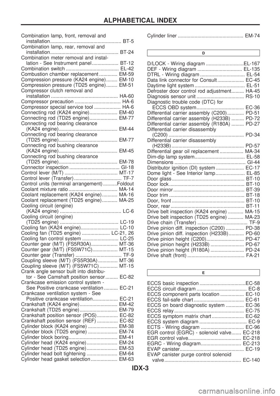
Combination lamp, front, removal and
installation................................................... BT-5
Combination lamp, rear, removal and
installation................................................. BT-24
Combination meter removal and instal-
lation - See Instrument panel ................... BT-12
Combination switch ...................................... EL-42
Combustion chamber replacement ............. EM-59
Compression pressure (KA24 engine) ........ EM-10
Compression pressure (TD25 engine) ........ EM-51
Compressor clutch removal and
installation ................................................ HA-60
Compressor precaution ................................. HA-6
Compressor special service tool ................... HA-6
Connecting rod (KA24 engine).................... EM-40
Connecting rod (TD25 engine).................... EM-77
Connecting rod bearing clearance
(KA24 engine).......................................... EM-44
Connecting rod bearing clearance
(TD25 engine).......................................... EM-77
Connecting rod bushing clearance
(KA24 engine).......................................... EM-45
Connecting rod bushing clearance
(TD25 engine).......................................... EM-78
Connector inspection .................................... GI-18
Control lever (M/T) ...................................... MT-17
Control lever (Transfer) .................................. TF-7
Control units (terminal arrangement) ..........Foldout
Coolant mixture ratio ................................... MA-14
Coolant replacement (KA24 engine) ........... MA-16
Coolant replacement (TD25 engine) ........... MA-25
Cooling circuit (engine)
(KA24 engine) ............................................ LC-6
Cooling circuit (engine)
(TD25 engine) .......................................... LC-19
Cooling fan (KA24 engine)........................... LC-10
Cooling fan (TD25 engine) .................... LC-21, 26
Cooling fan control system .......................... LC-25
Counter gear (M/T) (FS5R30A)................... MT-36
Counter gear (M/T) (FS5W71C).................. MT-15
Counter gear (Transfer) ................................. TF-9
Coupling sleeve (M/T) (FS5R30A) .............. MT-36
Coupling sleeve (M/T) (FS5W71C) ............. MT-15
Crank angle sensor built into distribu-
tor - See Camshaft position sensor ......... EC-82
Crankcase emission control system -
See Positive crankcase ventilation .......... EC-21
Crankcase ventilation system - See
Positive crankcase ventilation.................. EC-21
Crankshaft (KA24 engine) ........................... EM-42
Crankshaft (TD25 engine) ........................... EM-79
Crankshaft position sensor (POS) ............... EC-82
Crankshaft position sensor (REF) ............... EC-82
Cylinder block (KA24 engine) ..................... EM-38
Cylinder block (TD25 engine) ..................... EM-74
Cylinder block boring................................... EM-41
Cylinder head (KA24 engine) ...................... EM-24
Cylinder head (TD25 engine) ...................... EM-53
Cylinder head bolt tightening ...................... EM-64
Cylinder head gasket selection ................... EM-63Cylinder liner ............................................... EM-74
D
D/LOCK - Wiring diagram ...........................EL-167
DEF - Wiring diagram ................................ EL-135
DTRL - Wiring diagram ................................ EL-54
Data link connector for Consult ................... EC-45
Daytime light system .................................... EL-51
Defroster door control rod adjustment......... HA-45
Diagnosis sensor unit .................................. RS-10
Diagnostic trouble code (DTC) for
ECCS OBD system.................................. EC-36
Differential carrier assembly (C200) ............ PD-51
Differential carrier assembly (H233B) ......... PD-72
Differential carrier assembly (R180A) ......... PD-27
Differential carrier disassembly
(C200) ...................................................... PD-34
Differential carrier disassembly
(H233B) .................................................... PD-57
Differential gear oil replacement ................. MA-34
Dim-dip lamp system.................................... EL-58
Dimensions ................................................... GI-44
Distributor ignition (DI) system .................... EC-17
Dome light - See Interior lamp ..................... EL-85
Door glass .................................................... BT-10
Door lock ...................................................... BT-10
Door mirror ................................................... BT-39
Door trim ...................................................... BT-18
Door, front .................................................... BT-10
Door, rear ..................................................... BT-11
Drive belt inspection (KA24 engine) ........... MA-15
Drive belt inspection (TD25 engine) ........... MA-23
Drive chain (Transfer) .................................... TF-9
Drive pinion diff. inspection (C200) ............. PD-38
Drive pinion diff. inspection (H233B) ........... PD-60
Drive pinion height (C200)........................... PD-47
Drive pinion height (H233B) ........................ PD-67
Drive pinion height (R180A) ........................ PD-24
Drive shaft (front) ......................................... FA-21
E
ECCS basic inspection .................................EC-58
ECCS circuit diagram .................................... EC-8
ECCS component parts location ................. EC-10
ECCS fail-safe chart .................................... EC-61
ECCS on board diagnostic system ............. EC-36
ECCS relay .................................................. EC-75
ECCS symptom matrix chart ....................... EC-62
ECCS system diagram .................................. EC-9
ECTS - Wiring diagram ............................... EC-96
EGR control (EGRC) - solenoid valve....... EC-218
EGR control valve...................................... EC-218
EGRC - Wiring diagram............................. EC-213
EVAP canister.............................................. EC-19
EVAP canister purge control solenoid
valve ....................................................... EC-140
ALPHABETICAL INDEX
IDX-3
Page 1552 of 1659
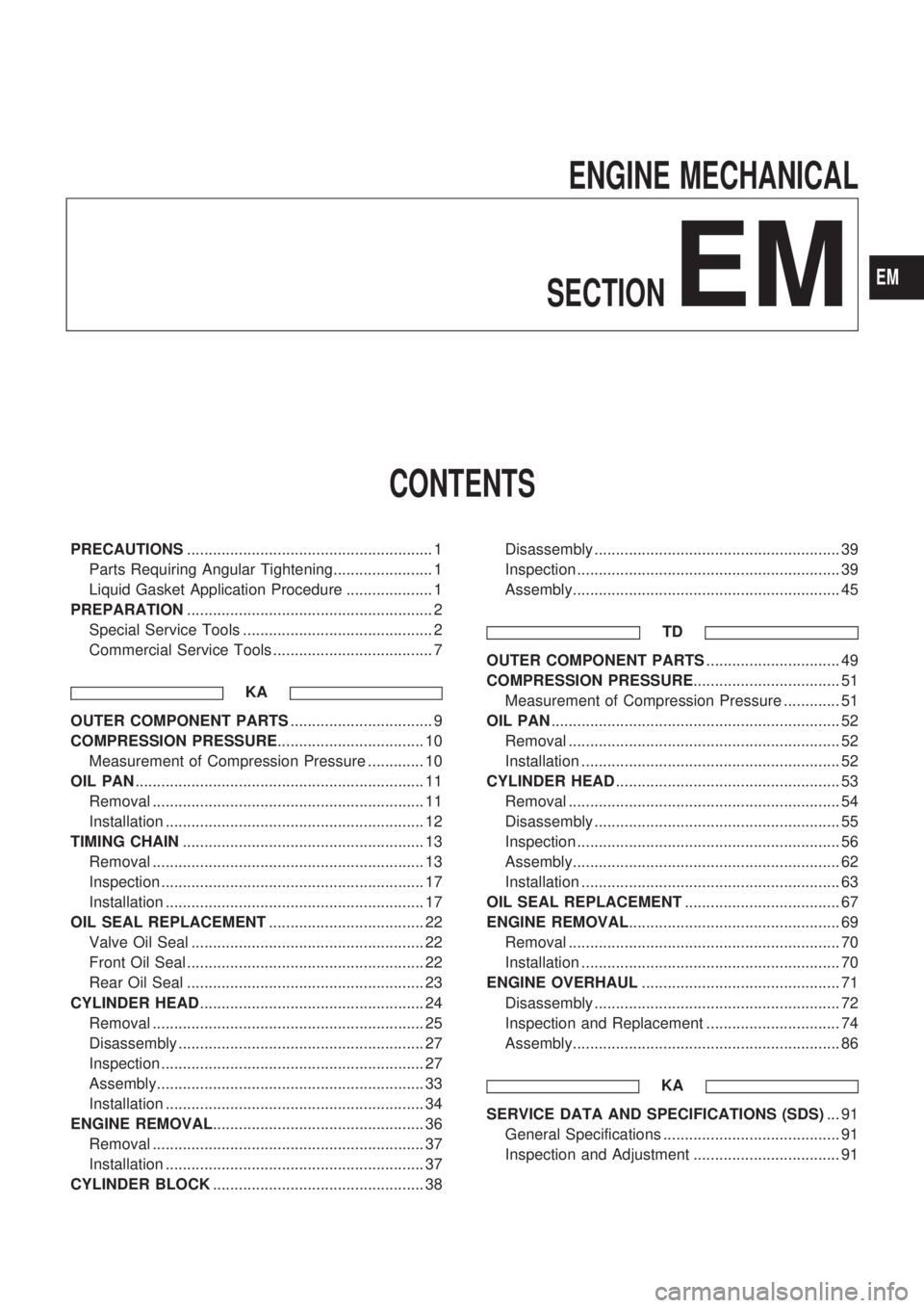
ENGINE MECHANICAL
SECTION
EM
CONTENTS
PRECAUTIONS......................................................... 1
Parts Requiring Angular Tightening....................... 1
Liquid Gasket Application Procedure .................... 1
PREPARATION......................................................... 2
Special Service Tools ............................................ 2
Commercial Service Tools ..................................... 7
KA
OUTER COMPONENT PARTS................................. 9
COMPRESSION PRESSURE.................................. 10
Measurement of Compression Pressure ............. 10
OIL PAN................................................................... 11
Removal ............................................................... 11
Installation ............................................................ 12
TIMING CHAIN........................................................ 13
Removal ............................................................... 13
Inspection ............................................................. 17
Installation ............................................................ 17
OIL SEAL REPLACEMENT.................................... 22
Valve Oil Seal ...................................................... 22
Front Oil Seal ....................................................... 22
Rear Oil Seal ....................................................... 23
CYLINDER HEAD.................................................... 24
Removal ............................................................... 25
Disassembly ......................................................... 27
Inspection ............................................................. 27
Assembly.............................................................. 33
Installation ............................................................ 34
ENGINE REMOVAL................................................. 36
Removal ............................................................... 37
Installation ............................................................ 37
CYLINDER BLOCK................................................. 38Disassembly ......................................................... 39
Inspection ............................................................. 39
Assembly.............................................................. 45
TD
OUTER COMPONENT PARTS............................... 49
COMPRESSION PRESSURE.................................. 51
Measurement of Compression Pressure ............. 51
OIL PAN................................................................... 52
Removal ............................................................... 52
Installation ............................................................ 52
CYLINDER HEAD.................................................... 53
Removal ............................................................... 54
Disassembly ......................................................... 55
Inspection ............................................................. 56
Assembly.............................................................. 62
Installation ............................................................ 63
OIL SEAL REPLACEMENT.................................... 67
ENGINE REMOVAL................................................. 69
Removal ............................................................... 70
Installation ............................................................ 70
ENGINE OVERHAUL.............................................. 71
Disassembly ......................................................... 72
Inspection and Replacement ............................... 74
Assembly.............................................................. 86
KA
SERVICE DATA AND SPECIFICATIONS (SDS)... 91
General Specifications ......................................... 91
Inspection and Adjustment .................................. 91
EM
Page 1557 of 1659
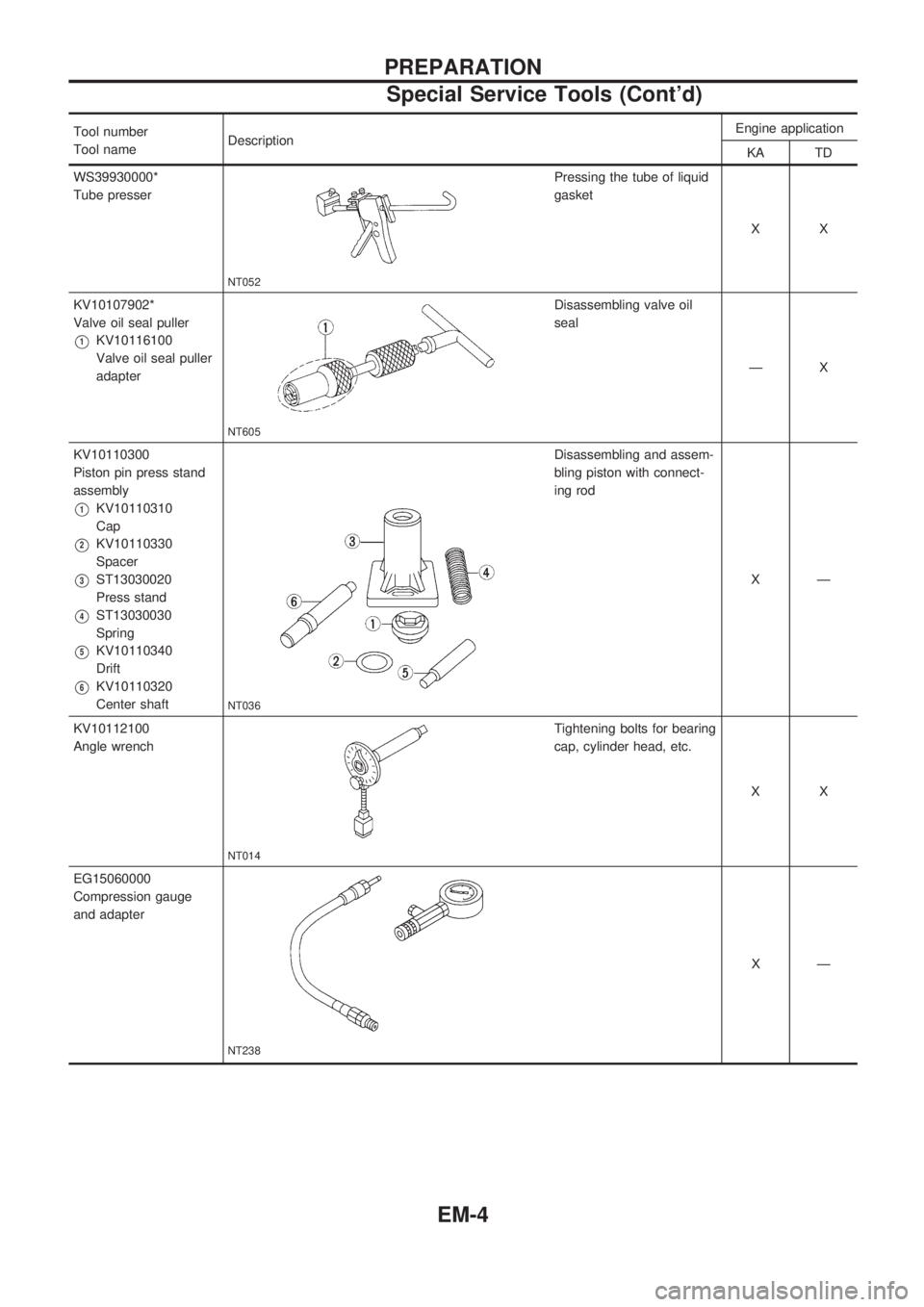
Tool number
Tool nameDescriptionEngine application
KA TD
WS39930000*
Tube presser
NT052
Pressing the tube of liquid
gasket
XX
KV10107902*
Valve oil seal puller
V1KV10116100
Valve oil seal puller
adapter
NT605
Disassembling valve oil
seal
ÐX
KV10110300
Piston pin press stand
assembly
V1KV10110310
Cap
V2KV10110330
Spacer
V3ST13030020
Press stand
V4ST13030030
Spring
V5KV10110340
Drift
V6KV10110320
Center shaft
NT036
Disassembling and assem-
bling piston with connect-
ing rod
XÐ
KV10112100
Angle wrench
NT014
Tightening bolts for bearing
cap, cylinder head, etc.
XX
EG15060000
Compression gauge
and adapter
NT238
XÐ
PREPARATION
Special Service Tools (Cont'd)
EM-4