NISSAN PICK-UP 1999 Repair Manual
Manufacturer: NISSAN, Model Year: 1999, Model line: PICK-UP, Model: NISSAN PICK-UP 1999Pages: 666, PDF Size: 16.21 MB
Page 311 of 666
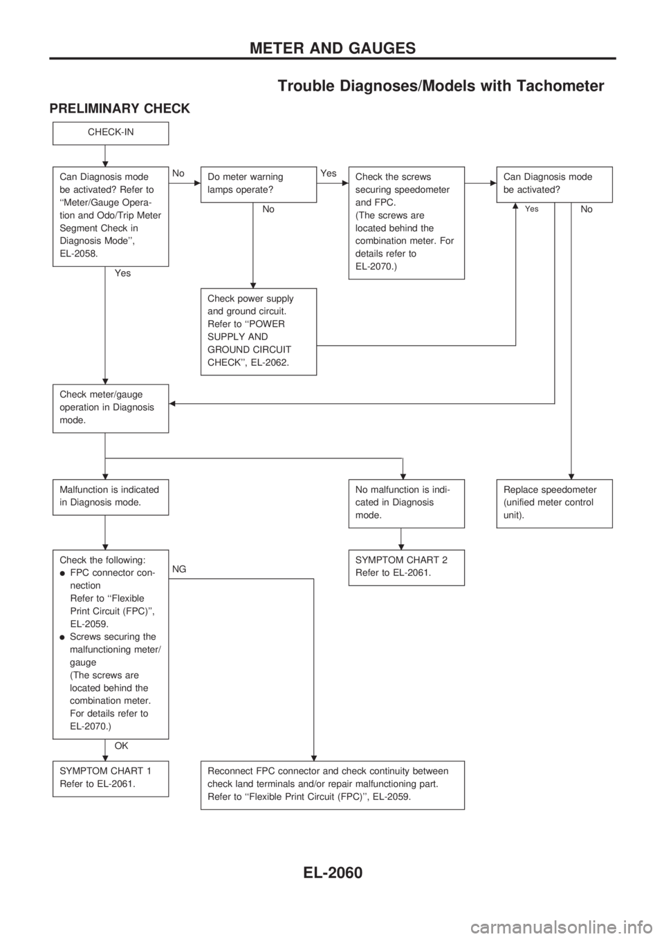
Trouble Diagnoses/Models with Tachometer
PRELIMINARY CHECK
CHECK-IN
Can Diagnosis mode
be activated? Refer to
``Meter/Gauge Opera-
tion and Odo/Trip Meter
Segment Check in
Diagnosis Mode'',
EL-2058.
Yes
cNo
Do meter warning
lamps operate?
No
cYes
Check the screws
securing speedometer
and FPC.
(The screws are
located behind the
combination meter. For
details refer to
EL-2070.)cCan Diagnosis mode
be activated?
NomYes
Check power supply
and ground circuit.
Refer to ``POWER
SUPPLY AND
GROUND CIRCUIT
CHECK'', EL-2062.
Check meter/gauge
operation in Diagnosis
mode.b
Malfunction is indicated
in Diagnosis mode.No malfunction is indi-
cated in Diagnosis
mode.Replace speedometer
(unified meter control
unit).
Check the following:
lFPC connector con-
nection
Refer to ``Flexible
Print Circuit (FPC)'',
EL-2059.
lScrews securing the
malfunctioning meter/
gauge
(The screws are
located behind the
combination meter.
For details refer to
EL-2070.)
OK
NGSYMPTOM CHART 2
Refer to EL-2061.
SYMPTOM CHART 1
Refer to EL-2061.Reconnect FPC connector and check continuity between
check land terminals and/or repair malfunctioning part.
Refer to ``Flexible Print Circuit (FPC)'', EL-2059.
.
.
.
...
..
..
METER AND GAUGES
EL-2060
Page 312 of 666
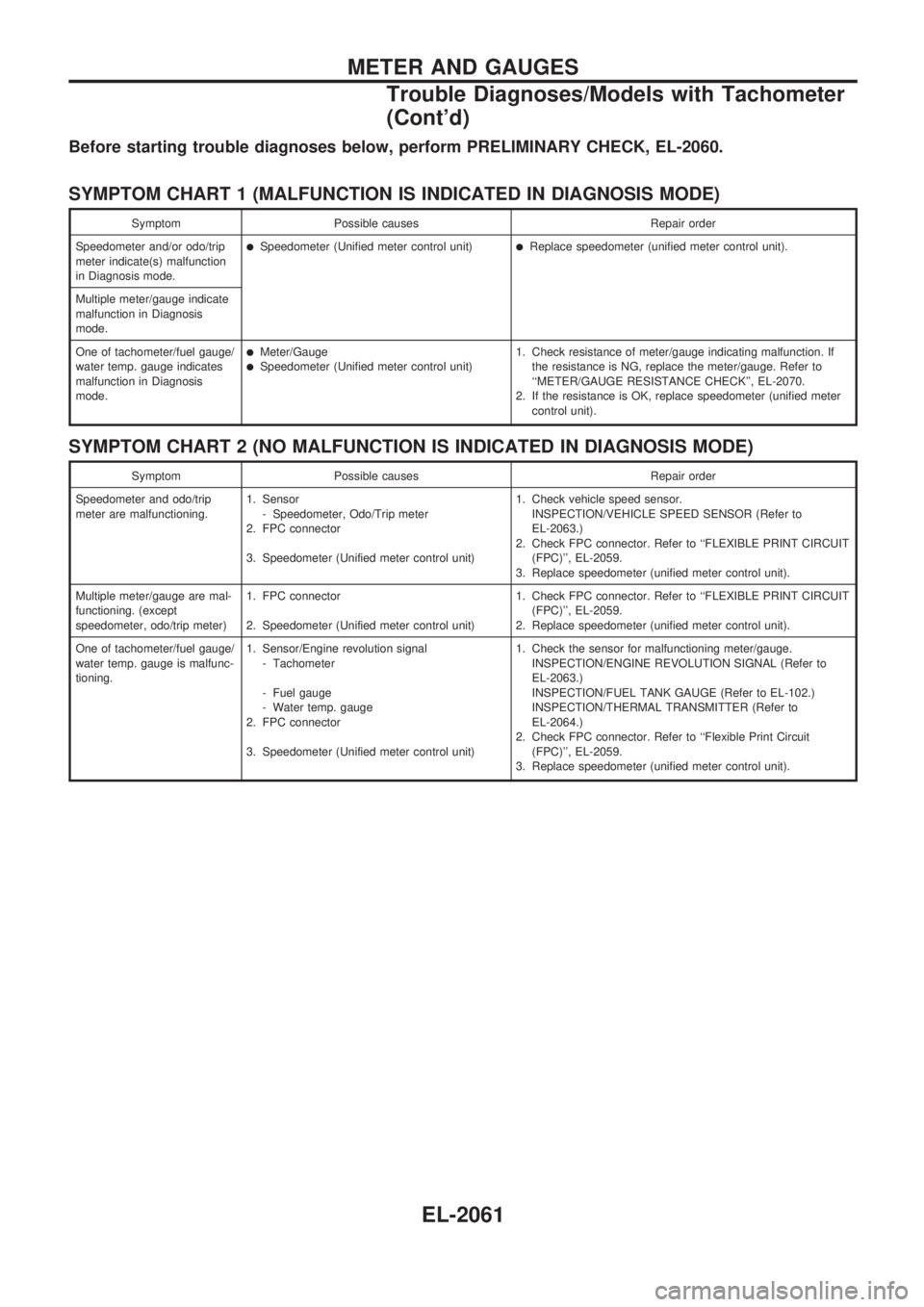
Before starting trouble diagnoses below, perform PRELIMINARY CHECK, EL-2060.
SYMPTOM CHART 1 (MALFUNCTION IS INDICATED IN DIAGNOSIS MODE)
Symptom Possible causes Repair order
Speedometer and/or odo/trip
meter indicate(s) malfunction
in Diagnosis mode.
lSpeedometer (Unified meter control unit)lReplace speedometer (unified meter control unit).
Multiple meter/gauge indicate
malfunction in Diagnosis
mode.
One of tachometer/fuel gauge/
water temp. gauge indicates
malfunction in Diagnosis
mode.
lMeter/GaugelSpeedometer (Unified meter control unit)1. Check resistance of meter/gauge indicating malfunction. If
the resistance is NG, replace the meter/gauge. Refer to
``METER/GAUGE RESISTANCE CHECK'', EL-2070.
2. If the resistance is OK, replace speedometer (unified meter
control unit).
SYMPTOM CHART 2 (NO MALFUNCTION IS INDICATED IN DIAGNOSIS MODE)
Symptom Possible causes Repair order
Speedometer and odo/trip
meter are malfunctioning.1. Sensor
- Speedometer, Odo/Trip meter
2. FPC connector
3. Speedometer (Unified meter control unit)1. Check vehicle speed sensor.
INSPECTION/VEHICLE SPEED SENSOR (Refer to
EL-2063.)
2. Check FPC connector. Refer to ``FLEXIBLE PRINT CIRCUIT
(FPC)'', EL-2059.
3. Replace speedometer (unified meter control unit).
Multiple meter/gauge are mal-
functioning. (except
speedometer, odo/trip meter)1. FPC connector
2. Speedometer (Unified meter control unit)1. Check FPC connector. Refer to ``FLEXIBLE PRINT CIRCUIT
(FPC)'', EL-2059.
2. Replace speedometer (unified meter control unit).
One of tachometer/fuel gauge/
water temp. gauge is malfunc-
tioning.1. Sensor/Engine revolution signal
- Tachometer
- Fuel gauge
- Water temp. gauge
2. FPC connector
3. Speedometer (Unified meter control unit)1. Check the sensor for malfunctioning meter/gauge.
INSPECTION/ENGINE REVOLUTION SIGNAL (Refer to
EL-2063.)
INSPECTION/FUEL TANK GAUGE (Refer to EL-102.)
INSPECTION/THERMAL TRANSMITTER (Refer to
EL-2064.)
2. Check FPC connector. Refer to ``Flexible Print Circuit
(FPC)'', EL-2059.
3. Replace speedometer (unified meter control unit).
METER AND GAUGES
Trouble Diagnoses/Models with Tachometer
(Cont'd)
EL-2061
Page 313 of 666
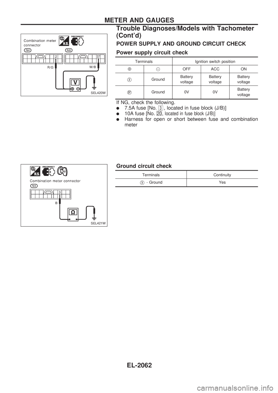
POWER SUPPLY AND GROUND CIRCUIT CHECK
Power supply circuit check
Terminals Ignition switch position
Å@OFF ACC ON
V2GroundBattery
voltageBattery
voltageBattery
voltage
V37Ground 0V 0VBattery
voltage
If NG, check the following.
l7.5A fuse [No.3, located in fuse block (J/B)]
l10A fuse [No.20 , located in fuse block (J/B)]
lHarness for open or short between fuse and combination
meter
Ground circuit check
Terminals Continuity
V3- Ground Yes
SEL420W
SEL421W
METER AND GAUGES
Trouble Diagnoses/Models with Tachometer
(Cont'd)
EL-2062
Page 314 of 666
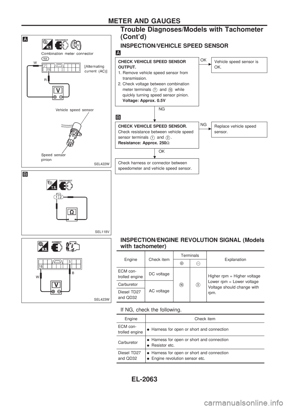
INSPECTION/VEHICLE SPEED SENSOR
CHECK VEHICLE SPEED SENSOR
OUTPUT.
1. Remove vehicle speed sensor from
transmission.
2. Check voltage between combination
meter terminals
V7andV15while
quickly turning speed sensor pinion.
Voltage: Approx. 0.5V
NG
cOK
Vehicle speed sensor is
OK.
CHECK VEHICLE SPEED SENSOR.
Check resistance between vehicle speed
sensor terminals
V1andV2.
Resistance: Approx. 250W
OK
cNG
Replace vehicle speed
sensor.
Check harness or connector between
speedometer and vehicle speed sensor.
INSPECTION/ENGINE REVOLUTION SIGNAL (Models
with tachometer)
Engine Check itemTerminals
ExplanationÅ@
ECM con-
trolled engineDC voltage
V16V3
Higher rpm = Higher voltage
Lower rpm = Lower voltage
Voltage should change with
rpm. Carburetor
AC voltage
Diesel TD27
and QD32
If NG, check the following.
Engine Check item
ECM con-
trolled engine
lHarness for open or short and connection
Carburetor
lHarness for open or short and connection
lResistor etc.
Diesel TD27
and QD32
lHarness for open or short and connection
lEngine revolution sensor etc.
SEL422W
SEL118V
SEL423W
.
.
METER AND GAUGES
Trouble Diagnoses/Models with Tachometer
(Cont'd)
EL-2063
Page 315 of 666
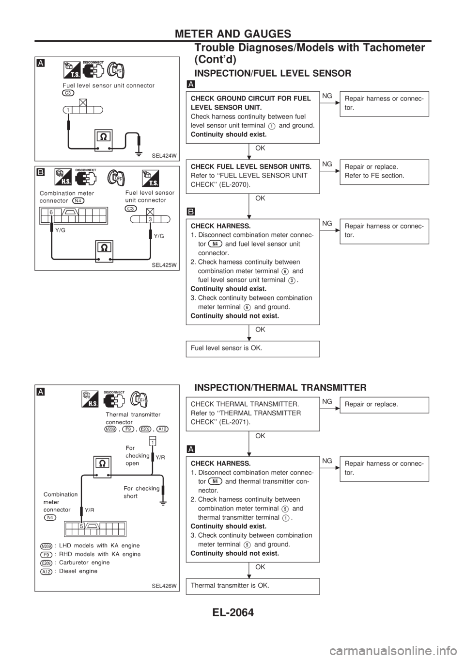
INSPECTION/FUEL LEVEL SENSOR
CHECK GROUND CIRCUIT FOR FUEL
LEVEL SENSOR UNIT.
Check harness continuity between fuel
level sensor unit terminal
V1and ground.
Continuity should exist.
OK
cNG
Repair harness or connec-
tor.
CHECK FUEL LEVEL SENSOR UNITS.
Refer to ``FUEL LEVEL SENSOR UNIT
CHECK'' (EL-2070).
OK
cNG
Repair or replace.
Refer to FE section.
CHECK HARNESS.
1. Disconnect combination meter connec-
tor
N4and fuel level sensor unit
connector.
2. Check harness continuity between
combination meter terminal
V6and
fuel level sensor unit terminal
V3.
Continuity should exist.
3. Check continuity between combination
meter terminal
V6and ground.
Continuity should not exist.
OK
cNG
Repair harness or connec-
tor.
Fuel level sensor is OK.
INSPECTION/THERMAL TRANSMITTER
CHECK THERMAL TRANSMITTER.
Refer to ``THERMAL TRANSMITTER
CHECK'' (EL-2071).
OK
cNG
Repair or replace.
CHECK HARNESS.
1. Disconnect combination meter connec-
tor
N4and thermal transmitter con-
nector.
2. Check harness continuity between
combination meter terminal
V5and
thermal transmitter terminal
V1.
Continuity should exist.
3. Check continuity between combination
meter terminal
V5and ground.
Continuity should not exist.
OK
cNG
Repair harness or connec-
tor.
Thermal transmitter is OK.
SEL424W
SEL425W
SEL426W
.
.
.
.
.
METER AND GAUGES
Trouble Diagnoses/Models with Tachometer
(Cont'd)
EL-2064
Page 316 of 666
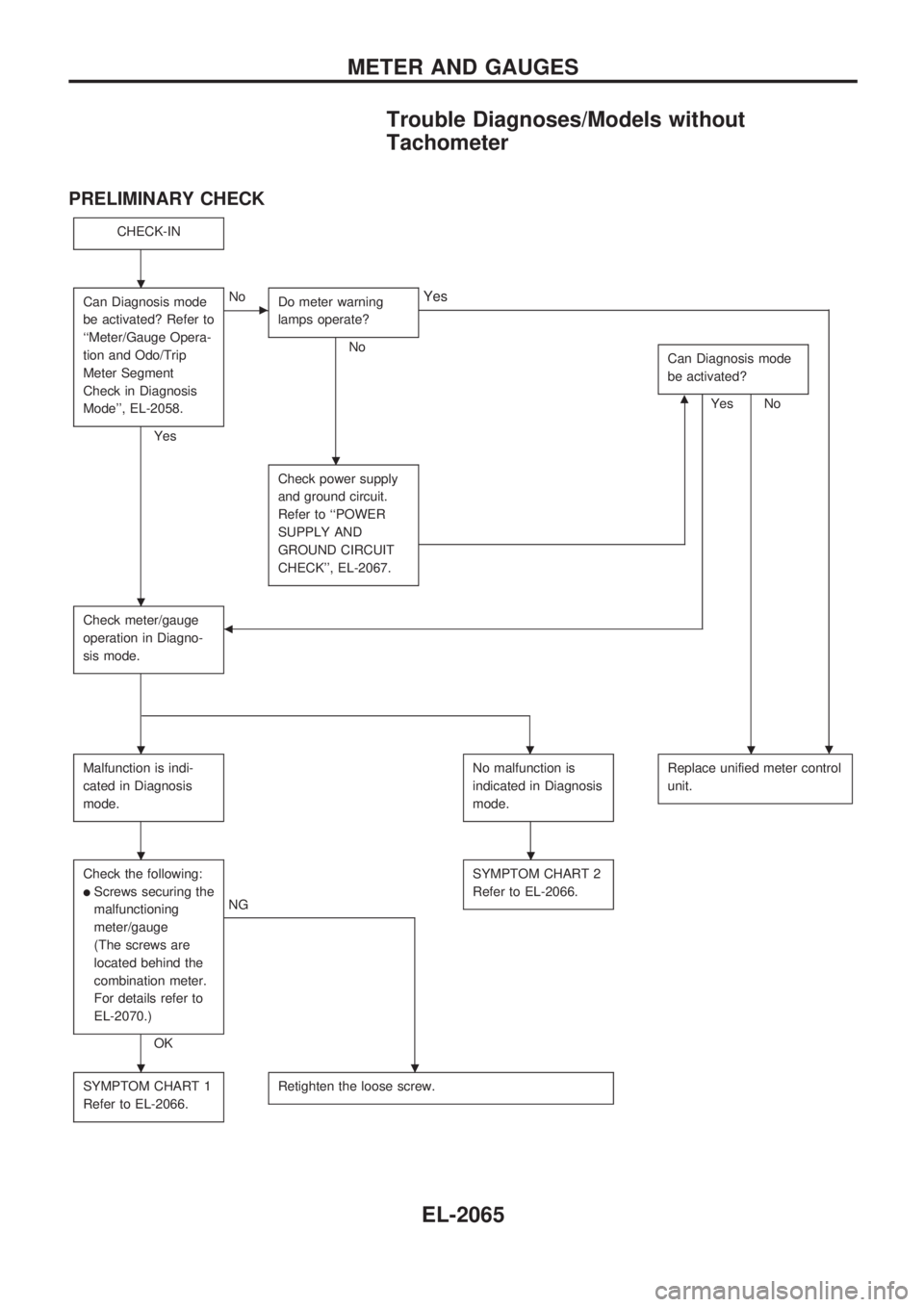
Trouble Diagnoses/Models without
Tachometer
PRELIMINARY CHECK
CHECK-IN
Can Diagnosis mode
be activated? Refer to
``Meter/Gauge Opera-
tion and Odo/Trip
Meter Segment
Check in Diagnosis
Mode'', EL-2058.
Yes
cNo
Do meter warning
lamps operate?
No
.
Yes
Can Diagnosis mode
be activated?
NomYes
Check power supply
and ground circuit.
Refer to ``POWER
SUPPLY AND
GROUND CIRCUIT
CHECK'', EL-2067.
Check meter/gauge
operation in Diagno-
sis mode.b
Malfunction is indi-
cated in Diagnosis
mode.No malfunction is
indicated in Diagnosis
mode.Replace unified meter control
unit.
Check the following:
lScrews securing the
malfunctioning
meter/gauge
(The screws are
located behind the
combination meter.
For details refer to
EL-2070.)
OK
NGSYMPTOM CHART 2
Refer to EL-2066.
SYMPTOM CHART 1
Refer to EL-2066.Retighten the loose screw.
.
.
.
...
..
..
METER AND GAUGES
EL-2065
Page 317 of 666
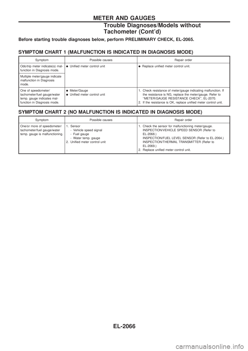
Before starting trouble diagnoses below, perform PRELIMINARY CHECK, EL-2065.
SYMPTOM CHART 1 (MALFUNCTION IS INDICATED IN DIAGNOSIS MODE)
Symptom Possible causes Repair order
Odo/trip meter indicate(s) mal-
function in Diagnosis mode.
lUnified meter control unitlReplace unified meter control unit.
Multiple meter/gauge indicate
malfunction in Diagnosis
mode.
One of speedometer/
tachometer/fuel gauge/water
temp. gauge indicates mal-
function in Diagnosis mode.
lMeter/GaugelUnified meter control unit1. Check resistance of meter/gauge indicating malfunction. If
the resistance is NG, replace the meter/gauge. Refer to
``METER/GAUGE RESISTANCE CHECK'', EL-2070.
2. If the resistance is OK, replace unified meter control unit.
SYMPTOM CHART 2 (NO MALFUNCTION IS INDICATED IN DIAGNOSIS MODE)
Symptom Possible causes Repair order
One/or more of speedometer/
tachometer/fuel gauge/water
temp. gauge is malfunctioning.1. Sensor
- Vehicle speed signal
- Fuel gauge
- Water temp. gauge
2. Unified meter control unit1. Check the sensor for malfunctioning meter/gauge.
INSPECTION/VEHICLE SPEED SENSOR (Refer to
EL-2068.)
INSPECTION/FUEL LEVEL SENSOR (Refer to EL-2064.)
INSPECTION/THERMAL TRANSMITTER (Refer to
EL-2069.)
2. Replace unified meter control unit.
METER AND GAUGES
Trouble Diagnoses/Models without
Tachometer (Cont'd)
EL-2066
Page 318 of 666
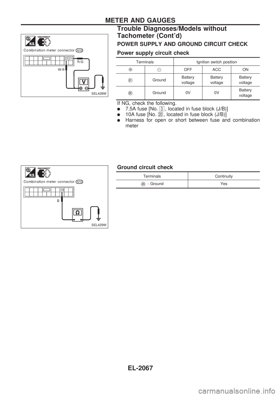
POWER SUPPLY AND GROUND CIRCUIT CHECK
Power supply circuit check
Terminals Ignition switch position
Å@OFF ACC ON
V21GroundBattery
voltageBattery
voltageBattery
voltage
V22Ground 0V 0VBattery
voltage
If NG, check the following.
l7.5A fuse [No.3, located in fuse block (J/B)]
l10A fuse [No.20, located in fuse block (J/B)]
lHarness for open or short between fuse and combination
meter
Ground circuit check
Terminals Continuity
V23- Ground Yes
SEL428W
SEL429W
METER AND GAUGES
Trouble Diagnoses/Models without
Tachometer (Cont'd)
EL-2067
Page 319 of 666
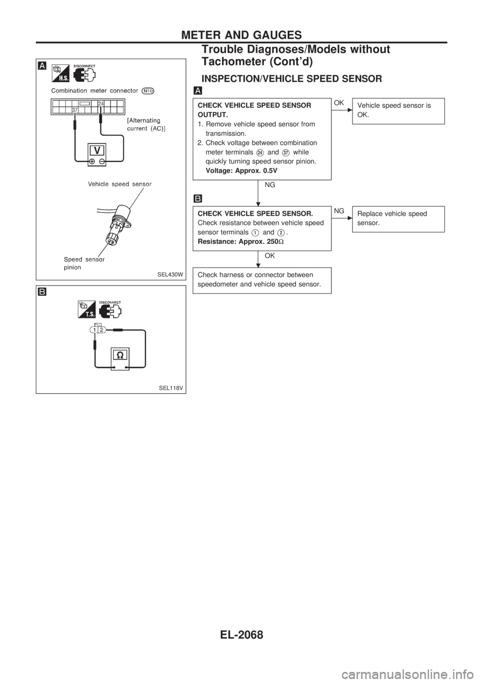
INSPECTION/VEHICLE SPEED SENSOR
CHECK VEHICLE SPEED SENSOR
OUTPUT.
1. Remove vehicle speed sensor from
transmission.
2. Check voltage between combination
meter terminals
V24andV37while
quickly turning speed sensor pinion.
Voltage: Approx. 0.5V
NG
cOK
Vehicle speed sensor is
OK.
CHECK VEHICLE SPEED SENSOR.
Check resistance between vehicle speed
sensor terminals
V1andV2.
Resistance: Approx. 250W
OK
cNG
Replace vehicle speed
sensor.
Check harness or connector between
speedometer and vehicle speed sensor.SEL430W
SEL118V
.
.
METER AND GAUGES
Trouble Diagnoses/Models without
Tachometer (Cont'd)
EL-2068
Page 320 of 666
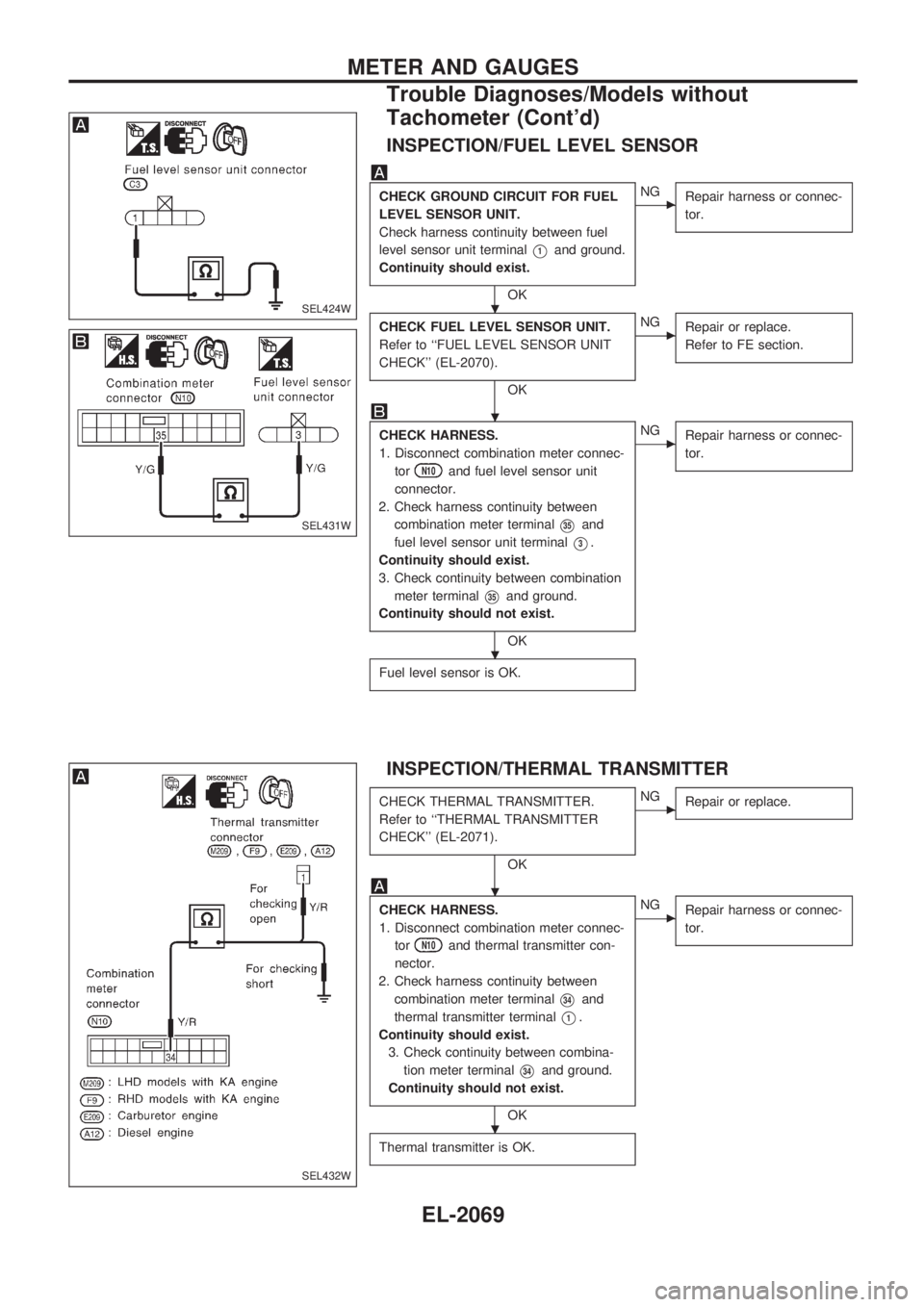
INSPECTION/FUEL LEVEL SENSOR
CHECK GROUND CIRCUIT FOR FUEL
LEVEL SENSOR UNIT.
Check harness continuity between fuel
level sensor unit terminal
V1and ground.
Continuity should exist.
OK
cNG
Repair harness or connec-
tor.
CHECK FUEL LEVEL SENSOR UNIT.
Refer to ``FUEL LEVEL SENSOR UNIT
CHECK'' (EL-2070).
OK
cNG
Repair or replace.
Refer to FE section.
CHECK HARNESS.
1. Disconnect combination meter connec-
tor
N10and fuel level sensor unit
connector.
2. Check harness continuity between
combination meter terminal
V35and
fuel level sensor unit terminal
V3.
Continuity should exist.
3. Check continuity between combination
meter terminal
V35and ground.
Continuity should not exist.
OK
cNG
Repair harness or connec-
tor.
Fuel level sensor is OK.
INSPECTION/THERMAL TRANSMITTER
CHECK THERMAL TRANSMITTER.
Refer to ``THERMAL TRANSMITTER
CHECK'' (EL-2071).
OK
cNG
Repair or replace.
CHECK HARNESS.
1. Disconnect combination meter connec-
tor
N10and thermal transmitter con-
nector.
2. Check harness continuity between
combination meter terminal
V34and
thermal transmitter terminal
V1.
Continuity should exist.
3. Check continuity between combina-
tion meter terminal
V34and ground.
Continuity should not exist.
OK
cNG
Repair harness or connec-
tor.
Thermal transmitter is OK.
SEL424W
SEL431W
SEL432W
.
.
.
.
.
METER AND GAUGES
Trouble Diagnoses/Models without
Tachometer (Cont'd)
EL-2069