FOR FRONTAL COLLISION
To repair the SRS for a frontal collision, perform the following steps.
When SRS is activated in a collision:
V01Replace the diagnosis sensor unit.
V02Remove the air bag modules.
V03Check the SRS components using the table shown below:
lReplace any SRS components showing visible signs of damage (dents, cracks, deformation).
V04Install new air bag modules.
V05Conduct self-diagnosis using CONSULT, and ``AIR BAG'' warning lamp. Refer to ``Self-diagnosis'' for
details (RS-2025). Ensure entire SRS operates properly.
When SRS is not activated in a collision:
V01Check the SRS components using the table shown below:
lReplace any SRS components showing visible signs of damage (dents, cracks, deformation).
V02Conduct self-diagnosis using CONSULT, and ``AIR BAG'' warning lamp. Refer to ``Self-diagnosis'' for
details (RS-2025). Ensure entire SRS operates properly.
SRS inspection
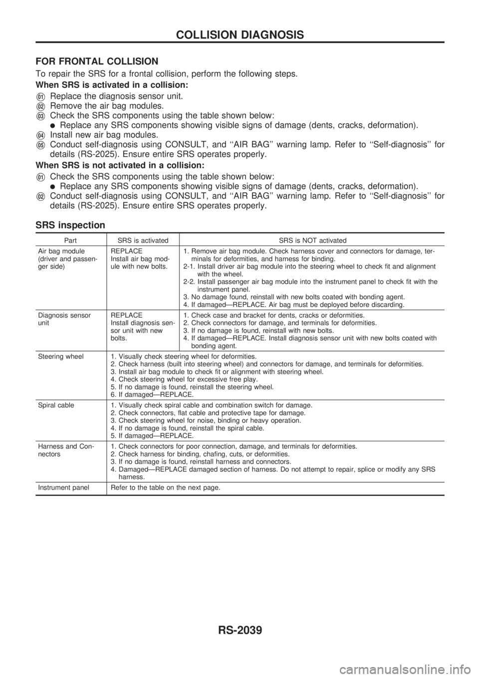
Part SRS is activated SRS is NOT activated
Air bag module
(driver and passen-
ger side)REPLACE
Install air bag mod-
ule with new bolts.1. Remove air bag module. Check harness cover and connectors for damage, ter-
minals for deformities, and harness for binding.
2-1. Install driver air bag module into the steering wheel to check fit and alignment
with the wheel.
2-2. Install passenger air bag module into the instrument panel to check fit with the
instrument panel.
3. No damage found, reinstall with new bolts coated with bonding agent.
4. If damagedÐREPLACE. Air bag must be deployed before discarding.
Diagnosis sensor
unitREPLACE
Install diagnosis sen-
sor unit with new
bolts.1. Check case and bracket for dents, cracks or deformities.
2. Check connectors for damage, and terminals for deformities.
3. If no damage is found, reinstall with new bolts.
4. If damagedÐREPLACE. Install diagnosis sensor unit with new bolts coated with
bonding agent.
Steering wheel 1. Visually check steering wheel for deformities.
2. Check harness (built into steering wheel) and connectors for damage, and terminals for deformities.
3. Install air bag module to check fit or alignment with steering wheel.
4. Check steering wheel for excessive free play.
5. If no damage is found, reinstall the steering wheel.
6. If damagedÐREPLACE.
Spiral cable 1. Visually check spiral cable and combination switch for damage.
2. Check connectors, flat cable and protective tape for damage.
3. Check steering wheel for noise, binding or heavy operation.
4. If no damage is found, reinstall the spiral cable.
5. If damagedÐREPLACE.
Harness and Con-
nectors1. Check connectors for poor connection, damage, and terminals for deformities.
2. Check harness for binding, chafing, cuts, or deformities.
3. If no damage is found, reinstall harness and connectors.
4. DamagedÐREPLACE damaged section of harness. Do not attempt to repair, splice or modify any SRS
harness.
Instrument panel Refer to the table on the next page.
COLLISION DIAGNOSIS
RS-2039
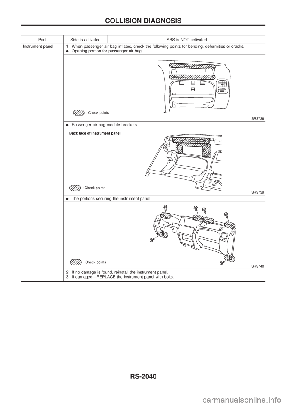
Part Side is activated SRS is NOT activated
Instrument panel 1. When passenger air bag inflates, check the following points for bending, deformities or cracks.
lOpening portion for passenger air bag
SRS738
lPassenger air bag module brackets
SRS739
lThe portions securing the instrument panel
SRS740
2. If no damage is found, reinstall the instrument panel.
3. If damagedÐREPLACE the instrument panel with bolts.
COLLISION DIAGNOSIS
RS-2040
STEERINGSYSTEM
SECTION
ST
MODIFICATION NOTICE:
Steering column has been changed.
CONTENTS
STEERING WHEEL AND STEERING
COLUMN .............................................................. 2002
Disassembly and Assembly ............................. 2002 SERVICE DATA AND SPECIFICATIONS
(SDS)
.................................................................... 2004
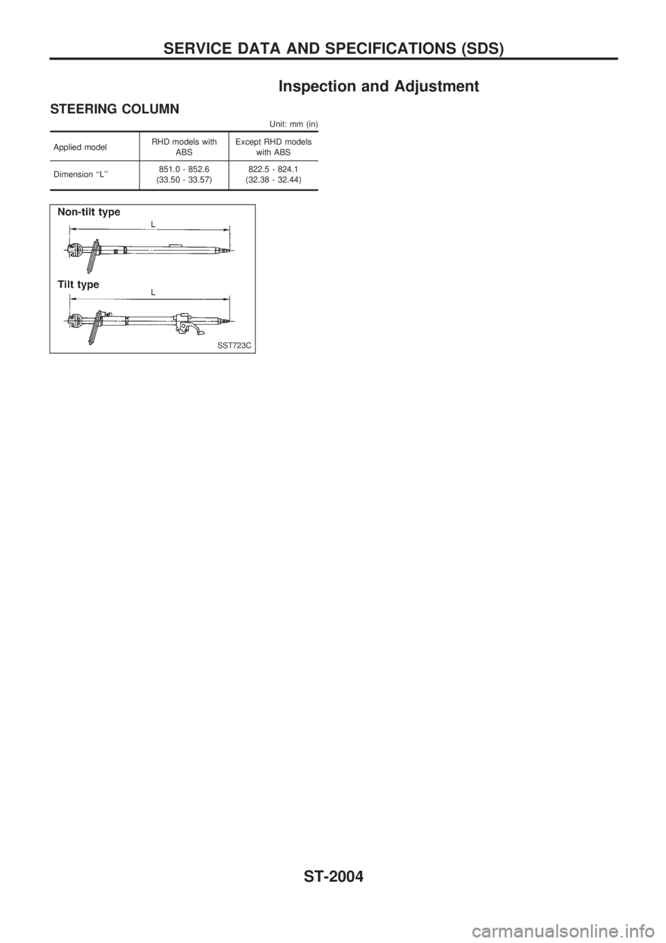
Inspection and Adjustment .............................. 2004
ST
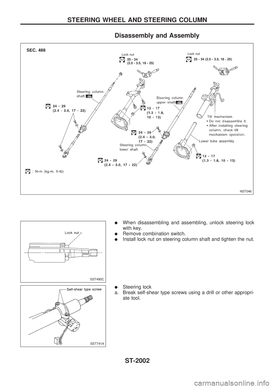
Disassembly and Assembly
lWhen disassembling and assembling, unlock steering lock
with key.
lRemove combination switch.
lInstall lock nut on steering column shaft and tighten the nut.
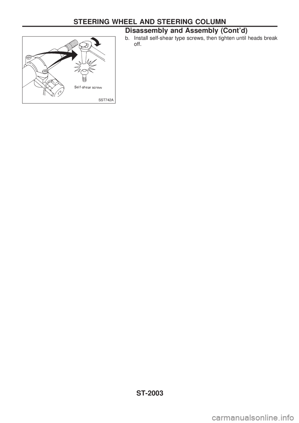
lSteering lock
a. Break self-shear type screws using a drill or other appropri-
ate tool.
NST046
..Lock nut.25 - 34 (2.5 - 3.5, 18 - 25)
.Lock nut
...25-34
(2.5 - 3.5, 18 - 25)
.
SST490C
SST741A
STEERING WHEEL AND STEERING COLUMN
ST-2002
