NISSAN PICK-UP 1999 Repair Manual
Manufacturer: NISSAN, Model Year: 1999, Model line: PICK-UP, Model: NISSAN PICK-UP 1999Pages: 666, PDF Size: 16.21 MB
Page 441 of 666
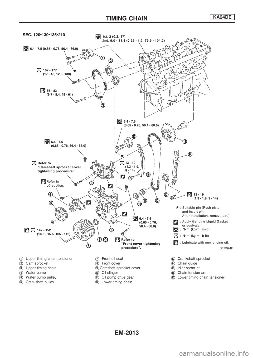
V1Upper timing chain tensioner
V2Cam sprocket
V3Upper timing chain
V4Water pump
V5Water pump pulley
V6Crankshaft pulley
V7Front oil seal
V8Front cover
V9Camshaft sprocket cover
V10Oil slinger
V11Oil pump drive gear
V12Lower timing chain
V13Crankshaft sprocket
V14Chain guide
V15Idler sprocket
V16Chain tension arm
V17Lower timing chain tensioner
SEM994F
TIMING CHAINKA24DE
EM-2013
Page 442 of 666
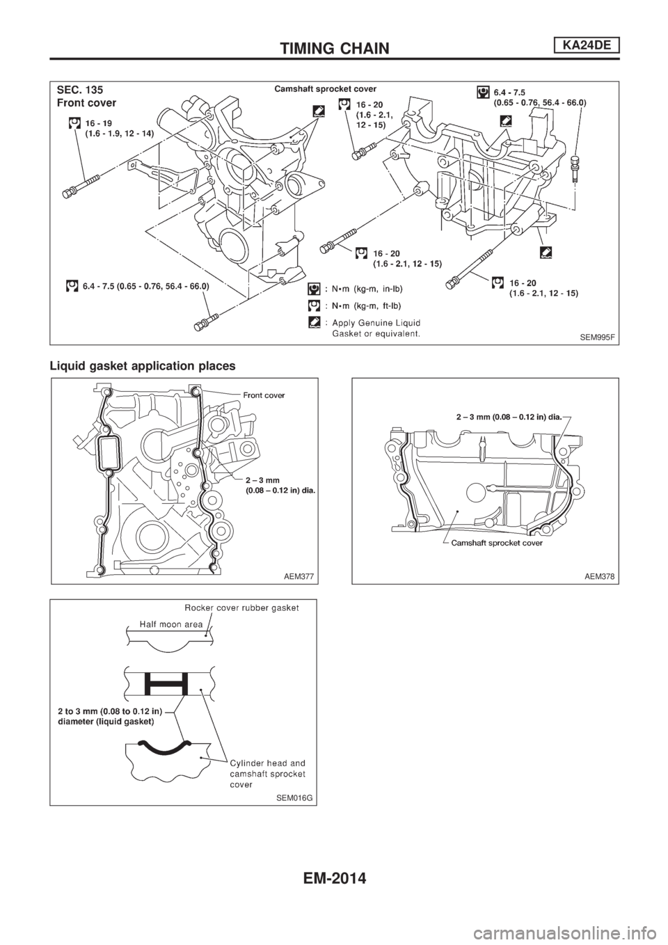
Liquid gasket application places
SEM995F
AEM377
SEM016G
AEM378
TIMING CHAINKA24DE
EM-2014
Page 443 of 666
Removal
CAUTION:
lAfter removing the timing chain, do not turn crankshaft
and camshaft separately, or valves will strike piston
heads.
lWhen installing chain tensioners or other sliding parts,
lubricate contacting surfaces with new engine oil.
lApply new engine oil to bolt threads and seat surfaces
when installing camshaft sprockets and crankshaft pul-
ley.
lDo not spill engine coolant on drive belts.
UPPER TIMING CHAIN
1. Remove air duct assembly.
2. Remove vacuum hoses, electrical harness connectors and
harness clamps.
3. Remove power steering drive belt.
4. Remove power steering pump and position it to one side.
5. Remove power steering pump bracket.
6. Remove idler pulley and bracket as well.
7. Remove ignition wires and spark plugs.
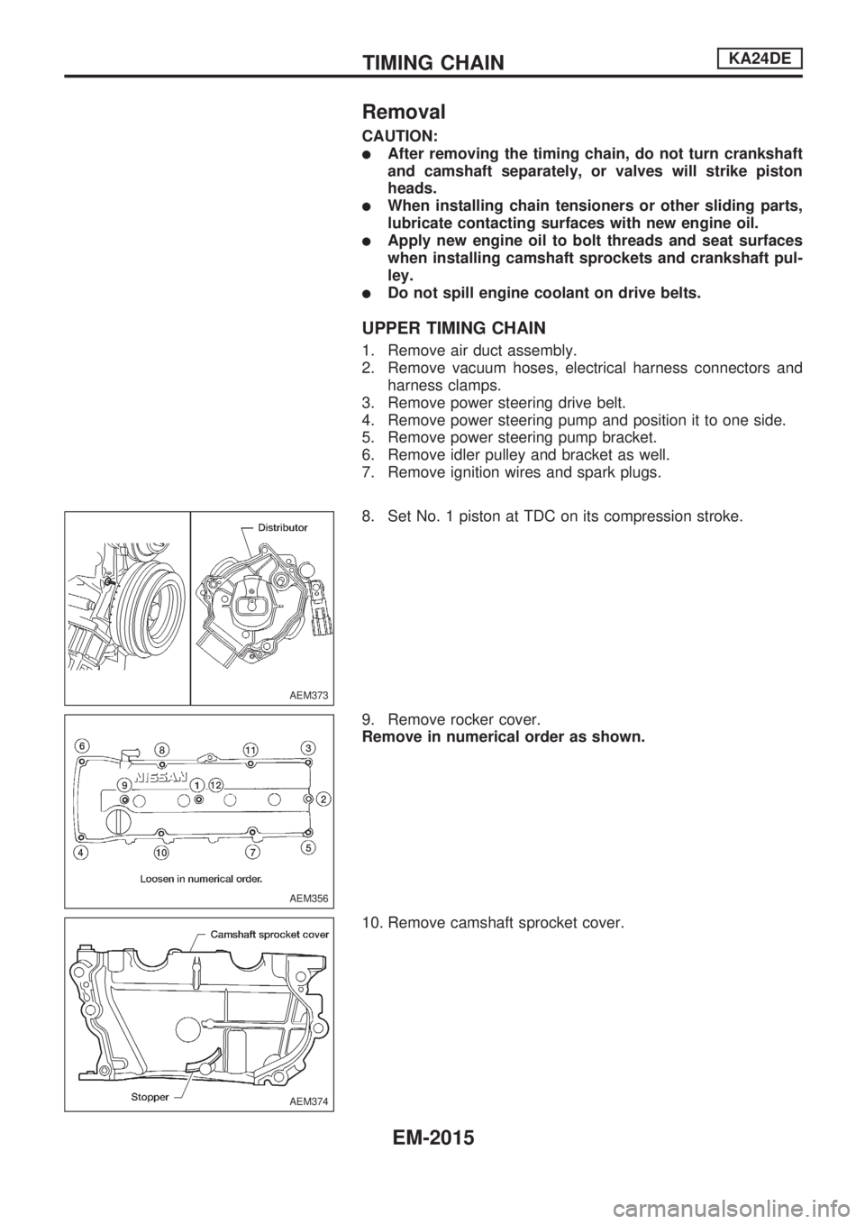
8. Set No. 1 piston at TDC on its compression stroke.
9. Remove rocker cover.
Remove in numerical order as shown.
10. Remove camshaft sprocket cover.
AEM373
AEM356
AEM374
TIMING CHAINKA24DE
EM-2015
Page 444 of 666
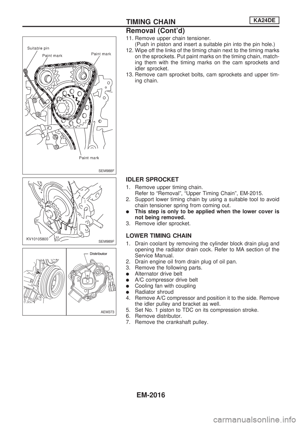
11. Remove upper chain tensioner.
(Push in piston and insert a suitable pin into the pin hole.)
12. Wipe off the links of the timing chain next to the timing marks
on the sprockets. Put paint marks on the timing chain, match-
ing them with the timing marks on the cam sprockets and
idler sprocket.
13. Remove cam sprocket bolts, cam sprockets and upper tim-
ing chain.
IDLER SPROCKET
1. Remove upper timing chain.
Refer to ªRemovalº, ªUpper Timing Chainº, EM-2015.
2. Support lower timing chain by using a suitable tool to avoid
chain tensioner spring from coming out.
lThis step is only to be applied when the lower cover is
not being removed.
3. Remove idler sprocket.
LOWER TIMING CHAIN
1. Drain coolant by removing the cylinder block drain plug and
opening the radiator drain cock. Refer to MA section of the
Service Manual.
2. Drain engine oil from drain plug of oil pan.
3. Remove the following parts.
lAlternator drive belt
lA/C compressor drive belt
lCooling fan with coupling
lRadiator shroud
4. Remove A/C compressor and position it to the side. Remove
the idler pulley and bracket as well.
5. Set No. 1 piston to TDC on its compression stroke.
6. Remove distributor.
7. Remove the crankshaft pulley.
SEM988F
SEM989F
AEM373
TIMING CHAINKA24DE
Removal (Cont'd)
EM-2016
Page 445 of 666
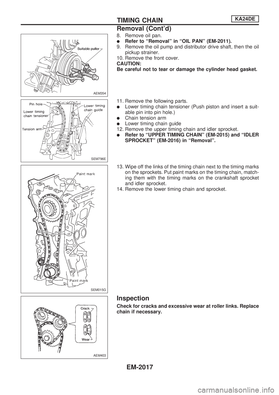
8. Remove oil pan.
lRefer to ªRemovalº in ªOIL PANº (EM-2011).
9. Remove the oil pump and distributor drive shaft, then the oil
pickup strainer.
10. Remove the front cover.
CAUTION:
Be careful not to tear or damage the cylinder head gasket.
11. Remove the following parts.
lLower timing chain tensioner (Push piston and insert a suit-
able pin into pin hole.)
lChain tension arm
lLower timing chain guide
12. Remove the upper timing chain and idler sprocket.
lRefer to ªUPPER TIMING CHAINº (EM-2015) and ªIDLER
SPROCKETº (EM-2016) in ªRemovalº.
13. Wipe off the links of the timing chain next to the timing marks
on the sprockets. Put paint marks on the timing chain, match-
ing them with the timing marks on the crankshaft sprocket
and idler sprocket.
14. Remove the lower timing chain and sprocket.
Inspection
Check for cracks and excessive wear at roller links. Replace
chain if necessary.
AEM354
SEM796E
SEM015G
AEM403
TIMING CHAINKA24DE
Removal (Cont'd)
EM-2017
Page 446 of 666
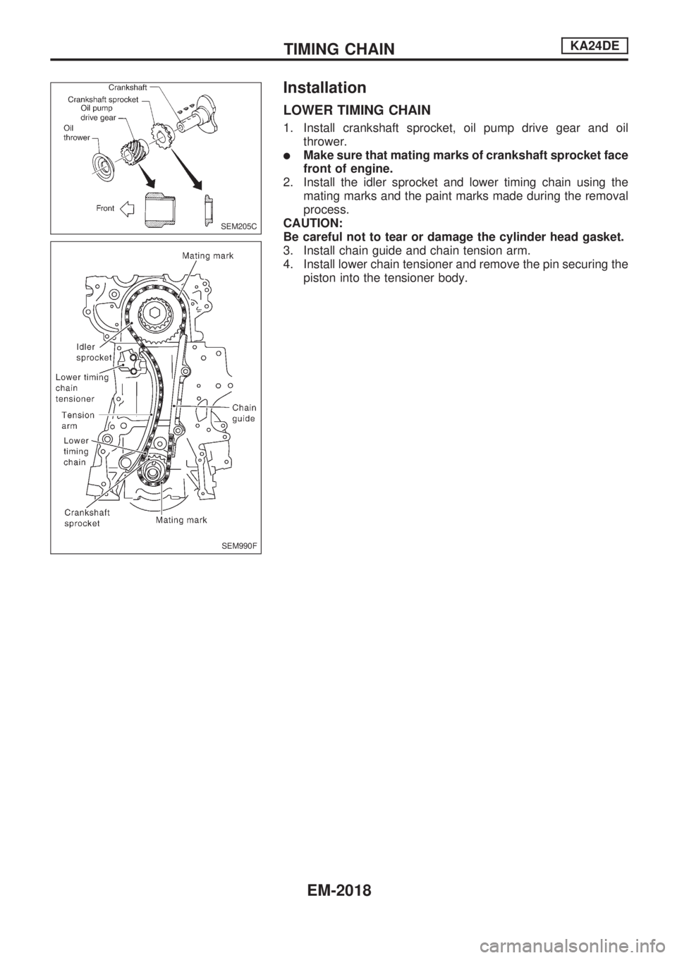
Installation
LOWER TIMING CHAIN
1. Install crankshaft sprocket, oil pump drive gear and oil
thrower.
lMake sure that mating marks of crankshaft sprocket face
front of engine.
2. Install the idler sprocket and lower timing chain using the
mating marks and the paint marks made during the removal
process.
CAUTION:
Be careful not to tear or damage the cylinder head gasket.
3. Install chain guide and chain tension arm.
4. Install lower chain tensioner and remove the pin securing the
piston into the tensioner body.
SEM205C
SEM990F
TIMING CHAINKA24DE
EM-2018
Page 447 of 666
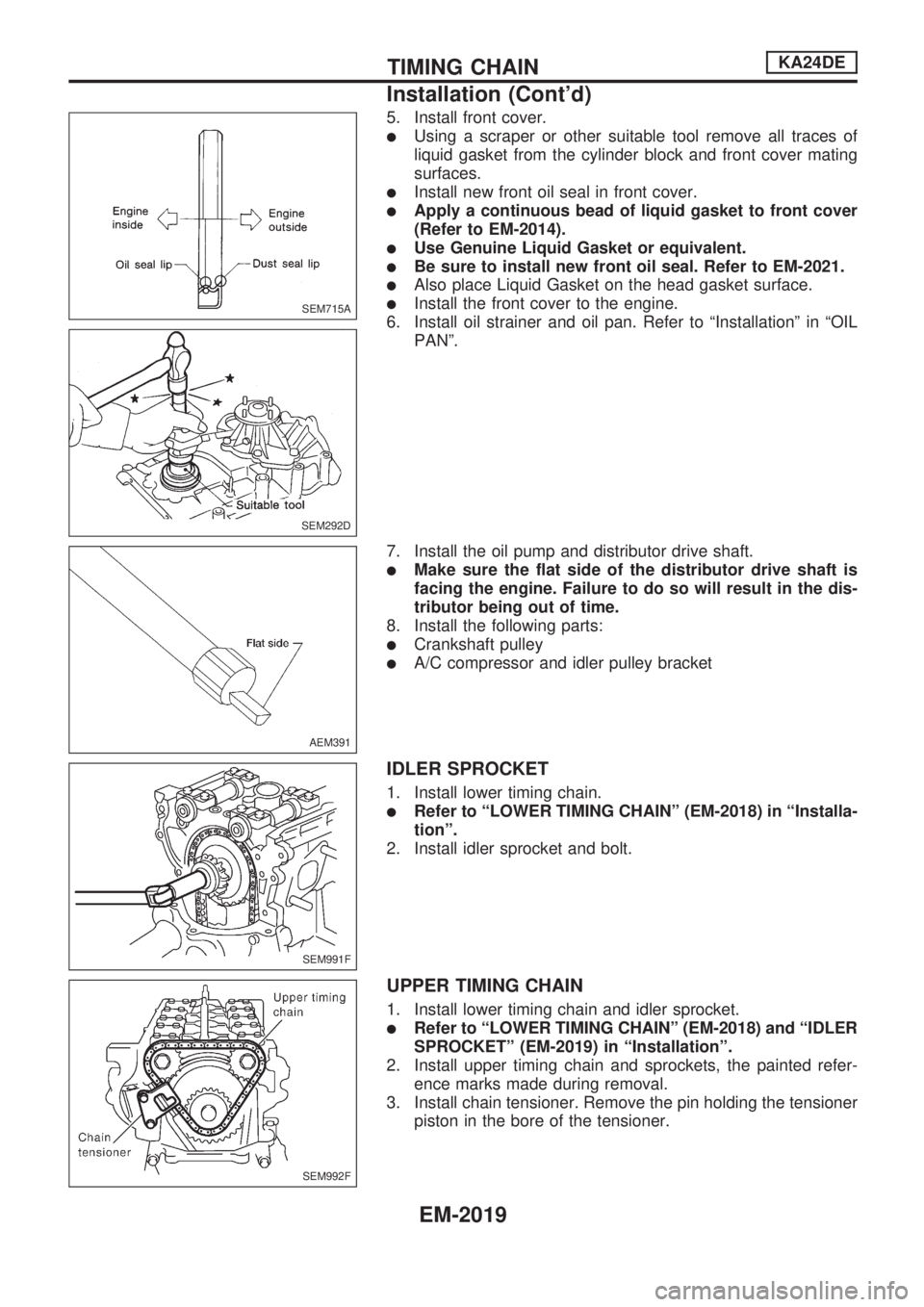
5. Install front cover.
lUsing a scraper or other suitable tool remove all traces of
liquid gasket from the cylinder block and front cover mating
surfaces.
lInstall new front oil seal in front cover.
lApply a continuous bead of liquid gasket to front cover
(Refer to EM-2014).
lUse Genuine Liquid Gasket or equivalent.
lBe sure to install new front oil seal. Refer to EM-2021.
lAlso place Liquid Gasket on the head gasket surface.
lInstall the front cover to the engine.
6. Install oil strainer and oil pan. Refer to ªInstallationº in ªOIL
PANº.
7. Install the oil pump and distributor drive shaft.
lMake sure the flat side of the distributor drive shaft is
facing the engine. Failure to do so will result in the dis-
tributor being out of time.
8. Install the following parts:
lCrankshaft pulley
lA/C compressor and idler pulley bracket
IDLER SPROCKET
1. Install lower timing chain.
lRefer to ªLOWER TIMING CHAINº (EM-2018) in ªInstalla-
tionº.
2. Install idler sprocket and bolt.
UPPER TIMING CHAIN
1. Install lower timing chain and idler sprocket.
lRefer to ªLOWER TIMING CHAINº (EM-2018) and ªIDLER
SPROCKETº (EM-2019) in ªInstallationº.
2. Install upper timing chain and sprockets, the painted refer-
ence marks made during removal.
3. Install chain tensioner. Remove the pin holding the tensioner
piston in the bore of the tensioner.
SEM715A
SEM292D
AEM391
SEM991F
SEM992F
TIMING CHAINKA24DE
Installation (Cont'd)
EM-2019
Page 448 of 666
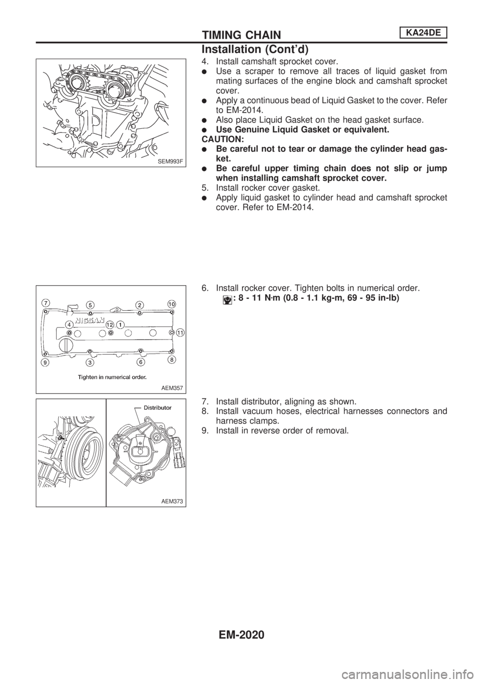
4. Install camshaft sprocket cover.
lUse a scraper to remove all traces of liquid gasket from
mating surfaces of the engine block and camshaft sprocket
cover.
lApply a continuous bead of Liquid Gasket to the cover. Refer
to EM-2014.
lAlso place Liquid Gasket on the head gasket surface.
lUse Genuine Liquid Gasket or equivalent.
CAUTION:
lBe careful not to tear or damage the cylinder head gas-
ket.
lBe careful upper timing chain does not slip or jump
when installing camshaft sprocket cover.
5. Install rocker cover gasket.
lApply liquid gasket to cylinder head and camshaft sprocket
cover. Refer to EM-2014.
6. Install rocker cover. Tighten bolts in numerical order.
:8-11Nzm (0.8 - 1.1 kg-m, 69 - 95 in-lb)
7. Install distributor, aligning as shown.
8. Install vacuum hoses, electrical harnesses connectors and
harness clamps.
9. Install in reverse order of removal.
SEM993F
AEM357
AEM373
TIMING CHAINKA24DE
Installation (Cont'd)
EM-2020
Page 449 of 666
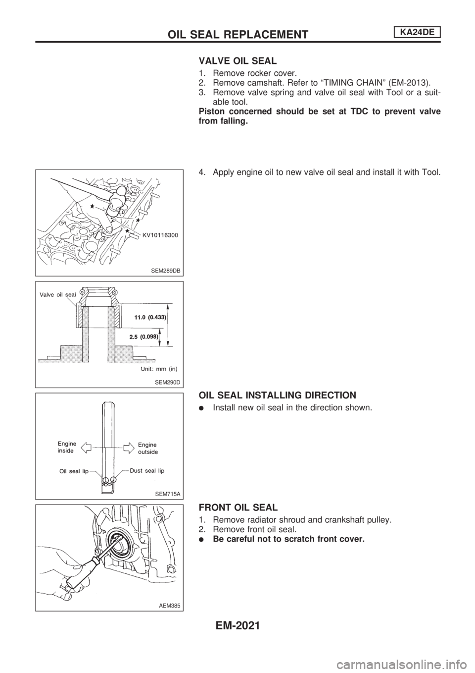
VALVE OIL SEAL
1. Remove rocker cover.
2. Remove camshaft. Refer to ªTIMING CHAINº (EM-2013).
3. Remove valve spring and valve oil seal with Tool or a suit-
able tool.
Piston concerned should be set at TDC to prevent valve
from falling.
4. Apply engine oil to new valve oil seal and install it with Tool.
OIL SEAL INSTALLING DIRECTION
lInstall new oil seal in the direction shown.
FRONT OIL SEAL
1. Remove radiator shroud and crankshaft pulley.
2. Remove front oil seal.
lBe careful not to scratch front cover.
SEM289DB
SEM290D
SEM715A
AEM385
OIL SEAL REPLACEMENTKA24DE
EM-2021
Page 450 of 666
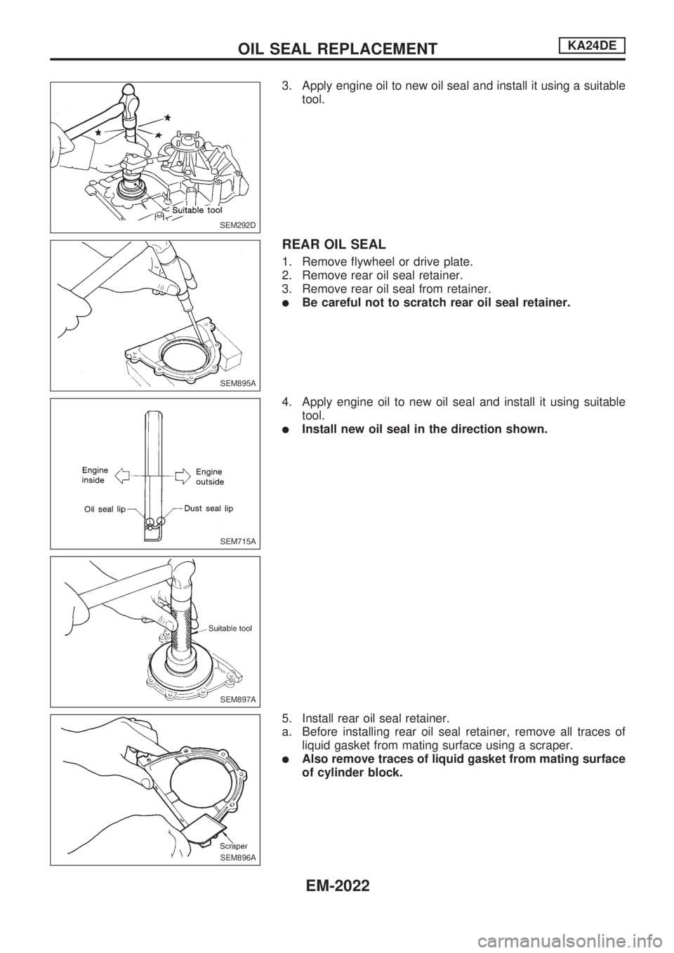
3. Apply engine oil to new oil seal and install it using a suitable
tool.
REAR OIL SEAL
1. Remove flywheel or drive plate.
2. Remove rear oil seal retainer.
3. Remove rear oil seal from retainer.
lBe careful not to scratch rear oil seal retainer.
4. Apply engine oil to new oil seal and install it using suitable
tool.
lInstall new oil seal in the direction shown.
5. Install rear oil seal retainer.
a. Before installing rear oil seal retainer, remove all traces of
liquid gasket from mating surface using a scraper.
lAlso remove traces of liquid gasket from mating surface
of cylinder block.
SEM292D
SEM895A
SEM715A
SEM897A
SEM896A
OIL SEAL REPLACEMENTKA24DE
EM-2022