NISSAN PICK-UP 2001 Repair Manual
Manufacturer: NISSAN, Model Year: 2001, Model line: PICK-UP, Model: NISSAN PICK-UP 2001Pages: 1306, PDF Size: 31.7 MB
Page 201 of 1306
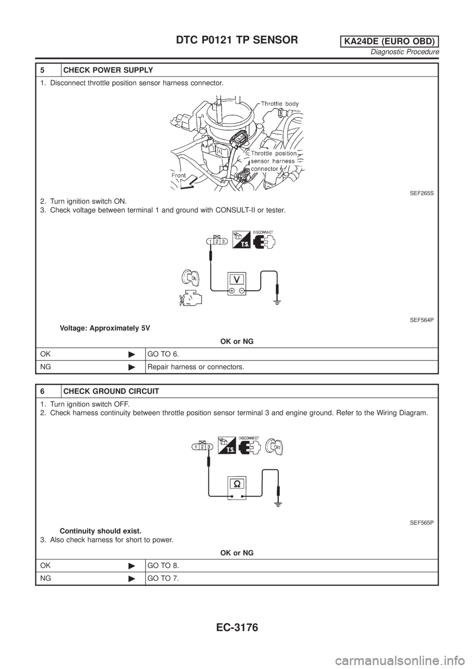
5 CHECK POWER SUPPLY
1. Disconnect throttle position sensor harness connector.
SEF265S
2. Turn ignition switch ON.
3. Check voltage between terminal 1 and ground with CONSULT-II or tester.
SEF564P
Voltage: Approximately 5V
OK or NG
OK©GO TO 6.
NG©Repair harness or connectors.
6 CHECK GROUND CIRCUIT
1. Turn ignition switch OFF.
2. Check harness continuity between throttle position sensor terminal 3 and engine ground. Refer to the Wiring Diagram.
SEF565P
Continuity should exist.
3. Also check harness for short to power.
OK or NG
OK©GO TO 8.
NG©GO TO 7.
DTC P0121 TP SENSORKA24DE (EURO OBD)
Diagnostic Procedure
EC-3176
Page 202 of 1306
7 DETECT MALFUNCTIONING PART
Check harness for open or short between ECM and throttle position sensor.
©Repair open circuit or short to power in harness or connectors.
8 CHECK INPUT SIGNAL CIRCUIT
1. Disconnect ECM harness connector.
2. Check harness continuity between ECM terminal 23 and terminal 2.
Refer to the Wiring Diagram.
Continuity should exist.
3. Also check harness for short to ground and short to power.
OK or NG
OK (With CONSULT-II)©GO TO 9.
OK (Without CONSULT-
II)©GO TO 10.
NG©Repair open circuit or short to ground or short to power in harness or connectors.
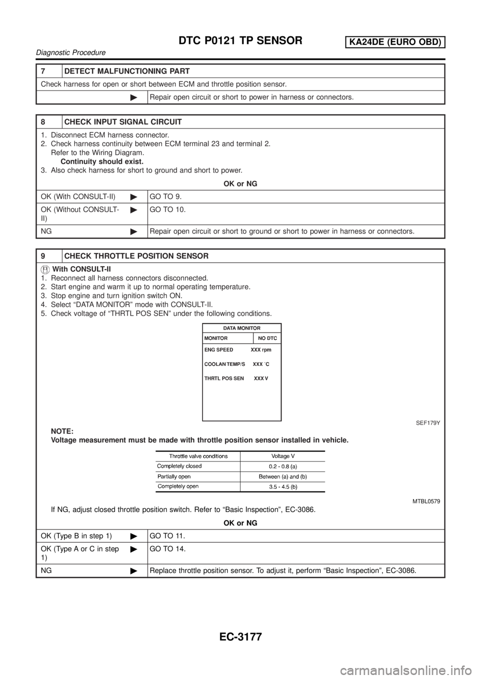
9 CHECK THROTTLE POSITION SENSOR
With CONSULT-II
1. Reconnect all harness connectors disconnected.
2. Start engine and warm it up to normal operating temperature.
3. Stop engine and turn ignition switch ON.
4. Select ªDATA MONITORº mode with CONSULT-II.
5. Check voltage of ªTHRTL POS SENº under the following conditions.
SEF179Y
NOTE:
Voltage measurement must be made with throttle position sensor installed in vehicle.
MTBL0579
If NG, adjust closed throttle position switch. Refer to ªBasic Inspectionº, EC-3086.
OK or NG
OK (Type B in step 1)©GO TO 11.
OK (Type A or C in step
1)©GO TO 14.
NG©Replace throttle position sensor. To adjust it, perform ªBasic Inspectionº, EC-3086.
DTC P0121 TP SENSORKA24DE (EURO OBD)
Diagnostic Procedure
EC-3177
Page 203 of 1306
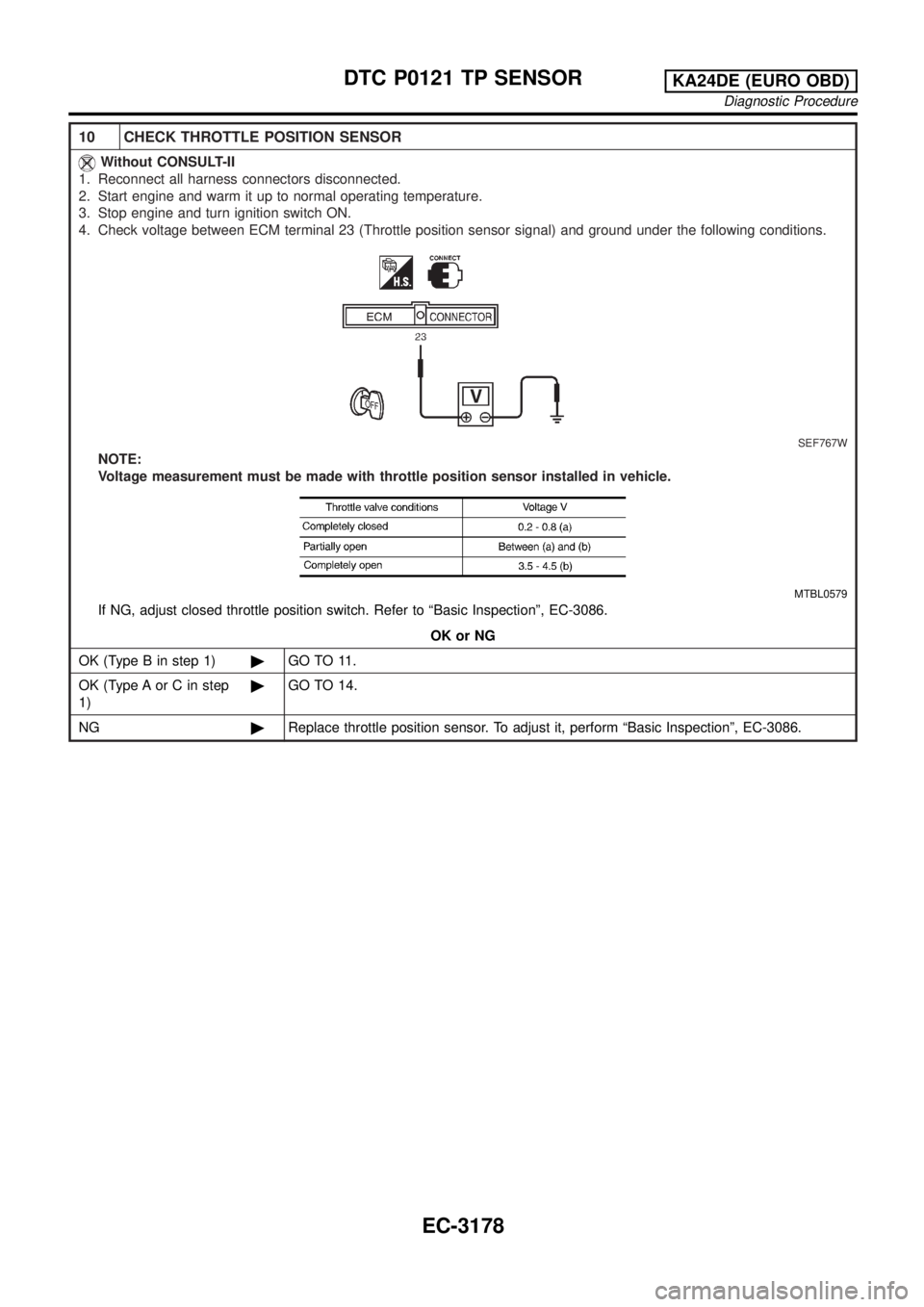
10 CHECK THROTTLE POSITION SENSOR
Without CONSULT-II
1. Reconnect all harness connectors disconnected.
2. Start engine and warm it up to normal operating temperature.
3. Stop engine and turn ignition switch ON.
4. Check voltage between ECM terminal 23 (Throttle position sensor signal) and ground under the following conditions.
SEF767W
NOTE:
Voltage measurement must be made with throttle position sensor installed in vehicle.
MTBL0579
If NG, adjust closed throttle position switch. Refer to ªBasic Inspectionº, EC-3086.
OK or NG
OK (Type B in step 1)©GO TO 11.
OK (Type A or C in step
1)©GO TO 14.
NG©Replace throttle position sensor. To adjust it, perform ªBasic Inspectionº, EC-3086.
DTC P0121 TP SENSORKA24DE (EURO OBD)
Diagnostic Procedure
EC-3178
Page 204 of 1306

11 CHECK MASS AIR FLOW SENSOR
1. Turn ignition switch ON.
2. Start engine and warm it up to normal operating temperature.
3. Check voltage between ECM terminal 54 (mass air flow sensor signal) and ground.
SEF326V
MTBL0326
4. If the voltage is out of specification, disconnect mass air flow sensor harness connector and connect it again. Repeat
above check.
5. If NG, remove mass air flow sensor from air duct. Check hot wire for damage or dust.
SEF893J
OK or NG
OK©GO TO 12.
NG©Replace mass air flow sensor.
DTC P0121 TP SENSORKA24DE (EURO OBD)
Diagnostic Procedure
EC-3179
Page 205 of 1306

12 CHECK CAMSHAFT POSITION SENSOR
1. Start engine and warm it up to normal operating temperature.
2. Check voltage between ECM terminals 49 or (44)* and engine ground, ECM terminals 44, 48 or (49, 53)* and engine
ground.
SEC273D
*: Model with NATS (Nissan Anti-Theft System)
OK or NG
OK©GO TO 13.
NG©Replace distributor assembly with camshaft position sensor.
DTC P0121 TP SENSORKA24DE (EURO OBD)
Diagnostic Procedure
EC-3180
Page 206 of 1306
![NISSAN PICK-UP 2001 Repair Manual 13 CHECK FUEL INJECTOR
1. Disconnect injector harness connector.
2. Check resistance between terminals as shown in the figure.
SEF836Q
Resistance: 10 - 14W[at 25ÉC (77ÉF)]
OK or NG
OK©GO TO 14.
NG� NISSAN PICK-UP 2001 Repair Manual 13 CHECK FUEL INJECTOR
1. Disconnect injector harness connector.
2. Check resistance between terminals as shown in the figure.
SEF836Q
Resistance: 10 - 14W[at 25ÉC (77ÉF)]
OK or NG
OK©GO TO 14.
NG�](/img/5/57372/w960_57372-205.png)
13 CHECK FUEL INJECTOR
1. Disconnect injector harness connector.
2. Check resistance between terminals as shown in the figure.
SEF836Q
Resistance: 10 - 14W[at 25ÉC (77ÉF)]
OK or NG
OK©GO TO 14.
NG©Replace fuel injector.
14 CHECK SHIELD CIRCUIT
1. Turn ignition switch OFF.
2. Remove joint connector-3.
3. Check the following.
+Continuity between joint connector-3 terminal 2 and ground
+Joint connector-3
(Refer to ªHARNESS LAYOUTº, EL section.)
Continuity should exist.
4. Also check harness for short to power.
5. Then reconnect joint connector.
OK or NG
OK©GO TO 15.
NG©Repair open circuit or short to power in harness or connectors.
15 CHECK INTERMITTENT INCIDENT
Perform ªTROUBLE DIAGNOSIS FOR INTERMITTENT INCIDENTº, EC-3123.
©INSPECTION END
DTC P0121 TP SENSORKA24DE (EURO OBD)
Diagnostic Procedure
EC-3181
Page 207 of 1306
Component DescriptionNEEC1558NOTE:
If DTC P0121, P0122 or P0123 is displayed with DTC P0510, first perform trouble diagnosis for DTC
P0510, EC-3301.
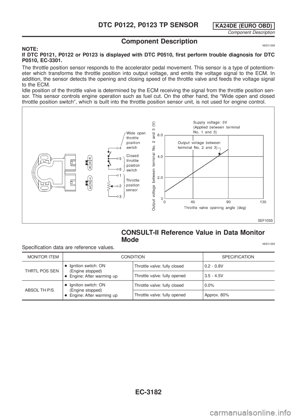
The throttle position sensor responds to the accelerator pedal movement. This sensor is a type of potentiom-
eter which transforms the throttle position into output voltage, and emits the voltage signal to the ECM. In
addition, the sensor detects the opening and closing speed of the throttle valve and feeds the voltage signal
to the ECM.
Idle position of the throttle valve is determined by the ECM receiving the signal from the throttle position sen-
sor. This sensor controls engine operation such as fuel cut. On the other hand, the ªWide open and closed
throttle position switchº, which is built into the throttle position sensor unit, is not used for engine control.
SEF105S
CONSULT-II Reference Value in Data Monitor
Mode
NEEC1559Specification data are reference values.
MONITOR ITEM CONDITION SPECIFICATION
THRTL POS SEN+Ignition switch: ON
(Engine stopped)
+Engine: After warming upThrottle valve: fully closed 0.2 - 0.8V
Throttle valve: fully opened 3.5 - 4.5V
ABSOL TH´P/S+Ignition switch: ON
(Engine stopped)
+Engine: After warming upThrottle valve: fully closed 0.0%
Throttle valve: fully opened Approx. 80%
DTC P0122, P0123 TP SENSORKA24DE (EURO OBD)
Component Description
EC-3182
Page 208 of 1306
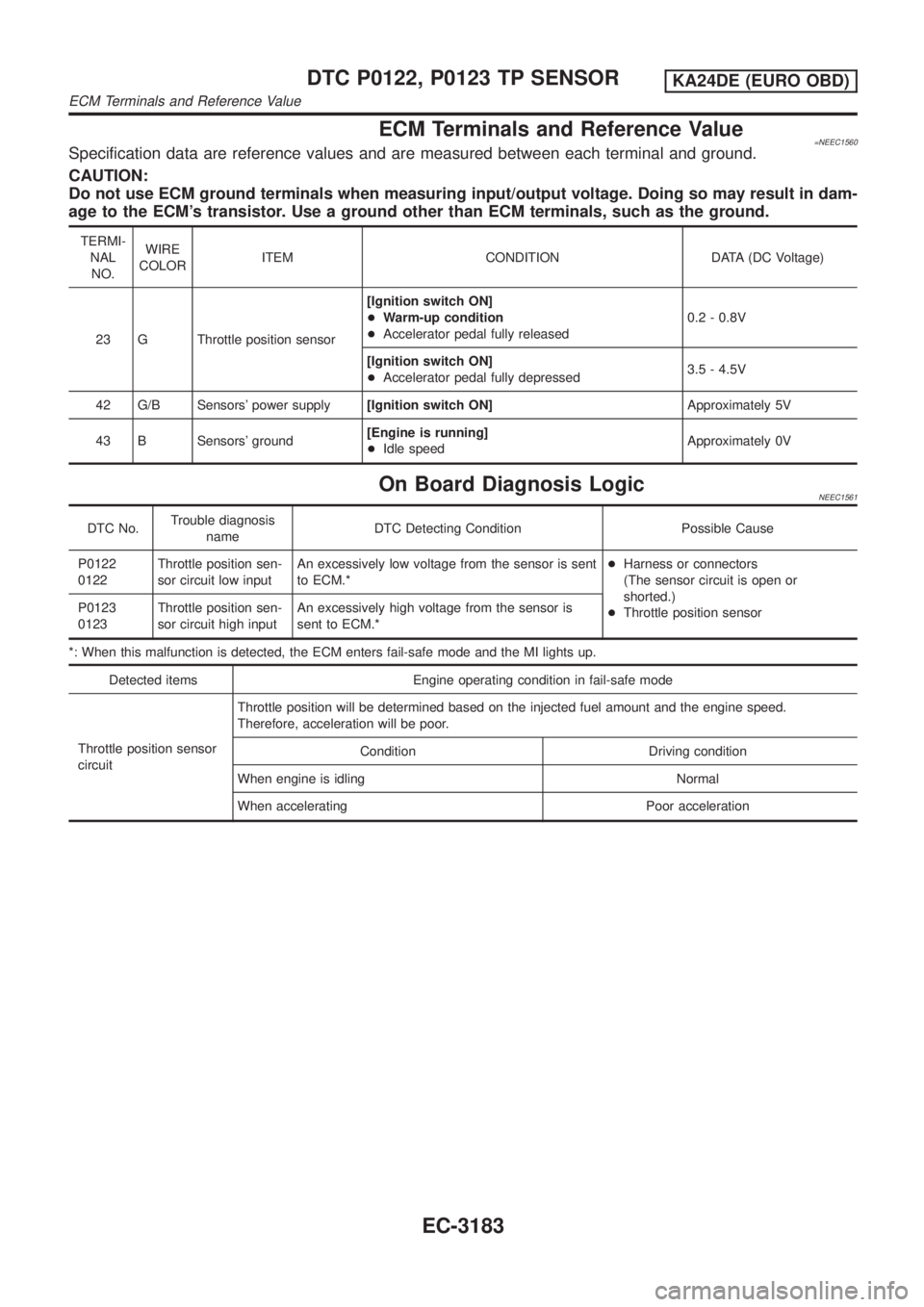
ECM Terminals and Reference Value=NEEC1560Specification data are reference values and are measured between each terminal and ground.
CAUTION:
Do not use ECM ground terminals when measuring input/output voltage. Doing so may result in dam-
age to the ECM's transistor. Use a ground other than ECM terminals, such as the ground.
TERMI-
NAL
NO.WIRE
COLORITEM CONDITION DATA (DC Voltage)
23 G Throttle position sensor[Ignition switch ON]
+Warm-up condition
+Accelerator pedal fully released0.2 - 0.8V
[Ignition switch ON]
+Accelerator pedal fully depressed3.5 - 4.5V
42 G/B Sensors' power supply[Ignition switch ON]Approximately 5V
43 B Sensors' ground[Engine is running]
+Idle speedApproximately 0V
On Board Diagnosis LogicNEEC1561
DTC No.Trouble diagnosis
nameDTC Detecting Condition Possible Cause
P0122
0122Throttle position sen-
sor circuit low inputAn excessively low voltage from the sensor is sent
to ECM.*+Harness or connectors
(The sensor circuit is open or
shorted.)
+Throttle position sensor P0123
0123Throttle position sen-
sor circuit high inputAn excessively high voltage from the sensor is
sent to ECM.*
*: When this malfunction is detected, the ECM enters fail-safe mode and the MI lights up.
Detected items Engine operating condition in fail-safe mode
Throttle position sensor
circuitThrottle position will be determined based on the injected fuel amount and the engine speed.
Therefore, acceleration will be poor.
Condition Driving condition
When engine is idling Normal
When accelerating Poor acceleration
DTC P0122, P0123 TP SENSORKA24DE (EURO OBD)
ECM Terminals and Reference Value
EC-3183
Page 209 of 1306
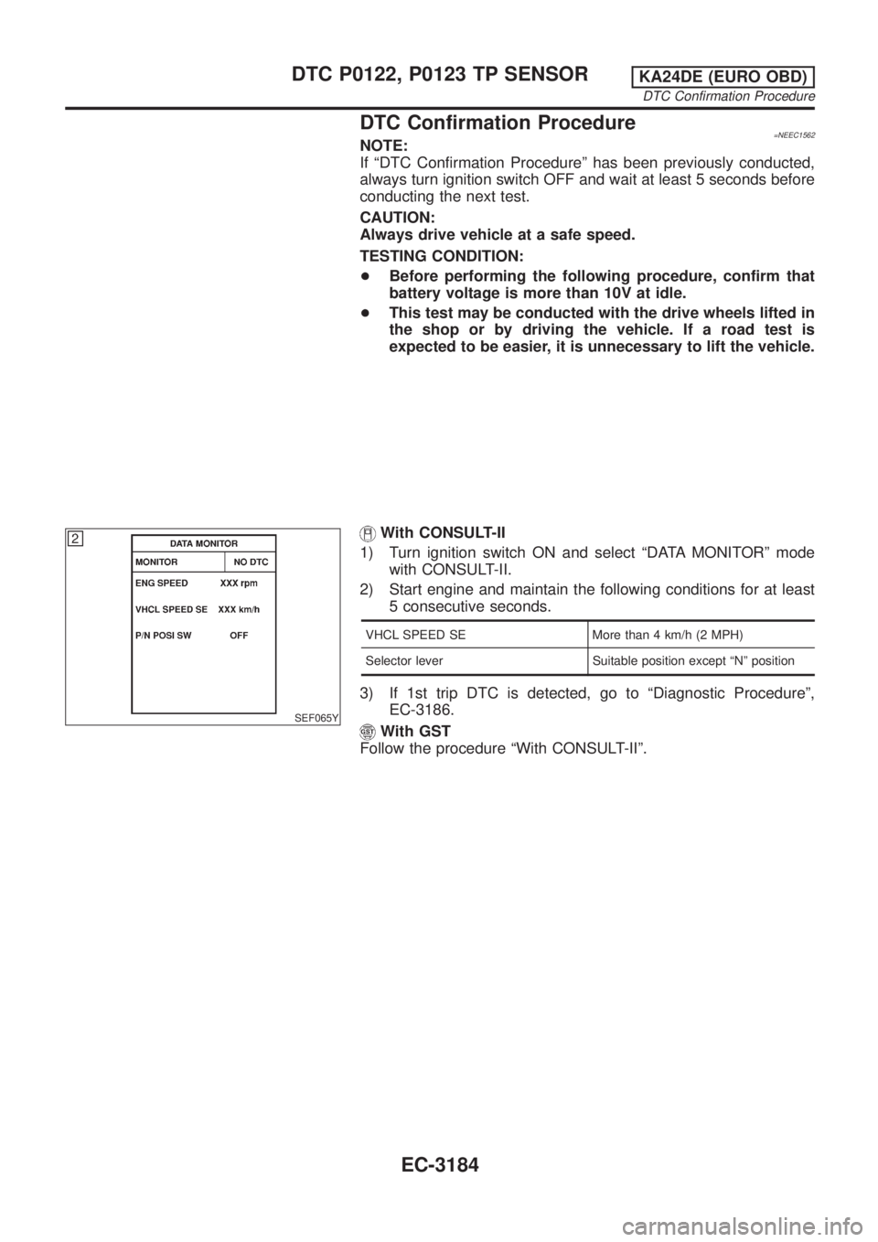
DTC Confirmation Procedure=NEEC1562NOTE:
If ªDTC Confirmation Procedureº has been previously conducted,
always turn ignition switch OFF and wait at least 5 seconds before
conducting the next test.
CAUTION:
Always drive vehicle at a safe speed.
TESTING CONDITION:
+Before performing the following procedure, confirm that
battery voltage is more than 10V at idle.
+This test may be conducted with the drive wheels lifted in
the shop or by driving the vehicle. If a road test is
expected to be easier, it is unnecessary to lift the vehicle.
SEF065Y
With CONSULT-II
1) Turn ignition switch ON and select ªDATA MONITORº mode
with CONSULT-II.
2) Start engine and maintain the following conditions for at least
5 consecutive seconds.
VHCL SPEED SE More than 4 km/h (2 MPH)
Selector lever Suitable position except ªNº position
3) If 1st trip DTC is detected, go to ªDiagnostic Procedureº,
EC-3186.
With GST
Follow the procedure ªWith CONSULT-IIº.
DTC P0122, P0123 TP SENSORKA24DE (EURO OBD)
DTC Confirmation Procedure
EC-3184
Page 210 of 1306

Wiring DiagramNEEC1563
GEC243A
DTC P0122, P0123 TP SENSORKA24DE (EURO OBD)
Wiring Diagram
EC-3185