NISSAN PICK-UP 2001 Repair Manual
PICK-UP 2001
NISSAN
NISSAN
https://www.carmanualsonline.info/img/5/57372/w960_57372-0.png
NISSAN PICK-UP 2001 Repair Manual
Trending: keyless, display, reset, wheelbase, battery replacement, belt, trailer
Page 391 of 1306
4 CHECK POWER SUPPLY
1. Turn ignition switch OFF.
2. Disconnect ignition coil harness connector.
SEC276D
3. Turn ignition switch ON.
4. Check voltage between terminal 7 and ground with CONSULT-II or tester.
AEC698
Voltage: Battery voltage
OK or NG
OK©GO TO 6.
NG©GO TO 5.
5 DETECT MALFUNCTIONING PART
Check the following.
+Harness connectors E101, M5
+Harness for open or short between ignition coil and ECM relay
+Harness for open or short between ECM relay and fuse
©Repair harness or connectors.
6 CHECK GROUND CIRCUIT
1. Turn ignition switch OFF.
2. Disconnect power transistor harness connector.
3. Check harness continuity between power transistor terminal 2 and engine ground. Refer to Wiring Diagram.
Continuity should exist.
4. Also check harness for short to power.
OK or NG
OK©GO TO 7.
NG©Repair open circuit or short to power in harness or connectors.
IGNITION SIGNALKA24DE (EURO OBD)
Diagnostic Procedure
EC-3366
Page 392 of 1306
7 CHECK INPUT SIGNAL CIRCUIT
1. Disconnect ECM harness connector.
2. Check harness continuity between ECM terminal 1 and power transistor terminal 1.
AEC700
Continuity should exist.
3. Also check harness for short to ground and short to power.
OK or NG
OK©GO TO 8.
NG©Repair open circuit or short to ground or short to power in harness or connectors.
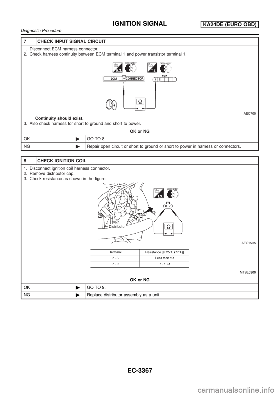
8 CHECK IGNITION COIL
1. Disconnect ignition coil harness connector.
2. Remove distributor cap.
3. Check resistance as shown in the figure.
AEC150A
MTBL0300
OK or NG
OK©GO TO 9.
NG©Replace distributor assembly as a unit.
IGNITION SIGNALKA24DE (EURO OBD)
Diagnostic Procedure
EC-3367
Page 393 of 1306
9 CHECK POWER TRANSISTOR
1. Disconnect camshaft position sensor & power transistor harness connector and ignition coil harness connector.
SEC276D
2. Check resistance between camshaft position sensor & power transistor and ignition coil terminals as follows. Refer to
wiring diagram.
MTBL1309
OK or NG
OK©GO TO 10.
NG©Replace distributor assembly.
10 CHECK INTERMITTENT INCIDENT
Perform ªTROUBLE DIAGNOSIS FOR INTERMITTENT INCIDENTº, EC-3123.
©INSPECTION END
IGNITION SIGNALKA24DE (EURO OBD)
Diagnostic Procedure
EC-3368
Page 394 of 1306
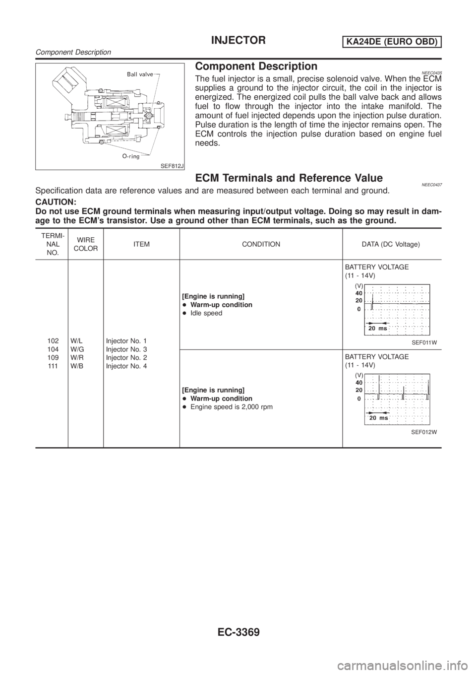
SEF812J
Component DescriptionNEEC0435The fuel injector is a small, precise solenoid valve. When the ECM
supplies a ground to the injector circuit, the coil in the injector is
energized. The energized coil pulls the ball valve back and allows
fuel to flow through the injector into the intake manifold. The
amount of fuel injected depends upon the injection pulse duration.
Pulse duration is the length of time the injector remains open. The
ECM controls the injection pulse duration based on engine fuel
needs.
ECM Terminals and Reference ValueNEEC0437Specification data are reference values and are measured between each terminal and ground.
CAUTION:
Do not use ECM ground terminals when measuring input/output voltage. Doing so may result in dam-
age to the ECM's transistor. Use a ground other than ECM terminals, such as the ground.
TERMI-
NAL
NO.WIRE
COLORITEM CONDITION DATA (DC Voltage)
102
104
109
111W/L
W/G
W/R
W/BInjector No. 1
Injector No. 3
Injector No. 2
Injector No. 4[Engine is running]
+Warm-up condition
+Idle speedBATTERY VOLTAGE
(11 - 14V)
SEF011W
[Engine is running]
+Warm-up condition
+Engine speed is 2,000 rpmBATTERY VOLTAGE
(11 - 14V)
SEF012W
INJECTORKA24DE (EURO OBD)
Component Description
EC-3369
Page 395 of 1306
Wiring DiagramNEEC0434
GEC254A
INJECTORKA24DE (EURO OBD)
Wiring Diagram
EC-3370
Page 396 of 1306
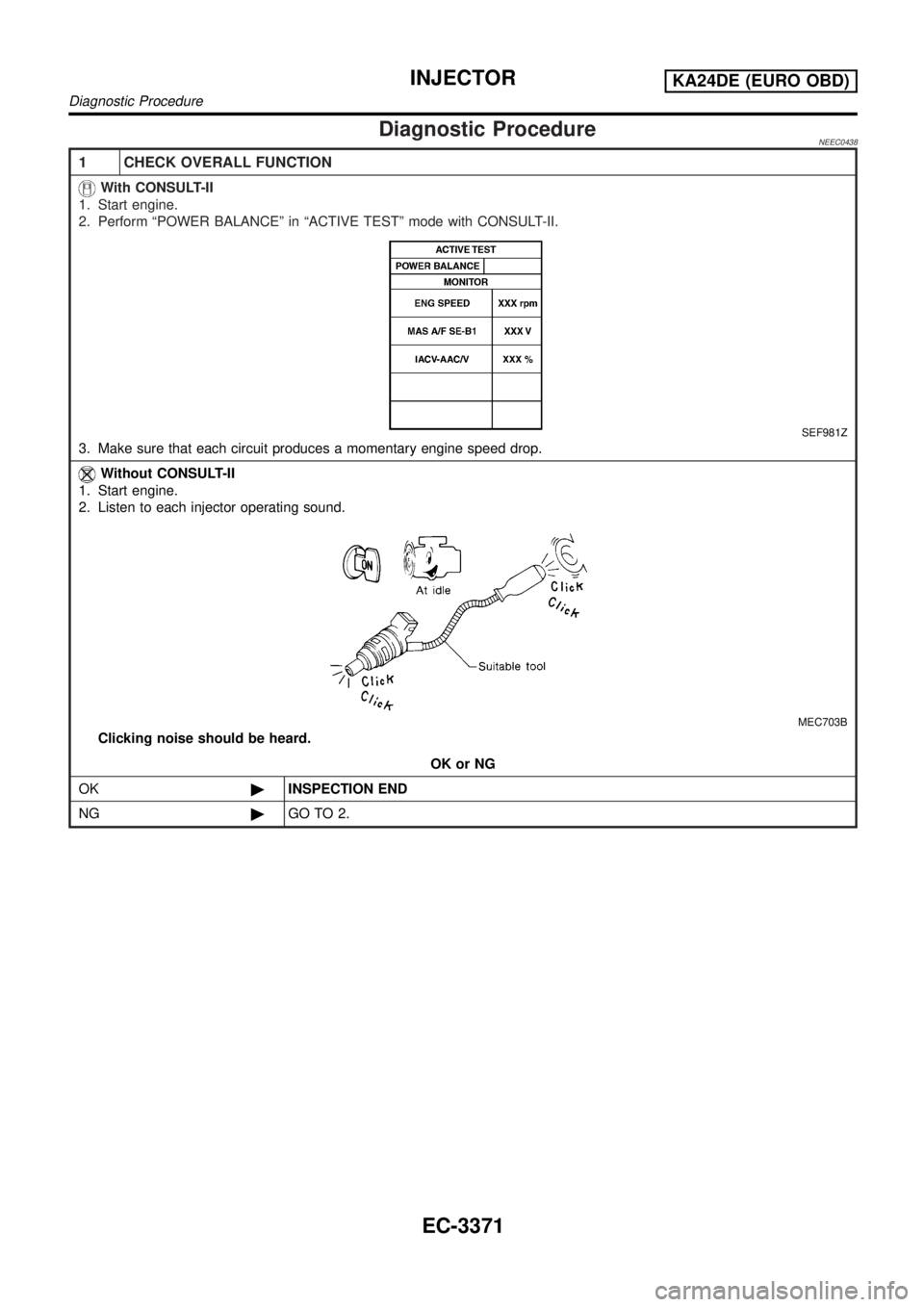
Diagnostic ProcedureNEEC0438
1 CHECK OVERALL FUNCTION
With CONSULT-II
1. Start engine.
2. Perform ªPOWER BALANCEº in ªACTIVE TESTº mode with CONSULT-II.
SEF981Z
3. Make sure that each circuit produces a momentary engine speed drop.
Without CONSULT-II
1. Start engine.
2. Listen to each injector operating sound.
MEC703B
Clicking noise should be heard.
OK or NG
OK©INSPECTION END
NG©GO TO 2.
INJECTORKA24DE (EURO OBD)
Diagnostic Procedure
EC-3371
Page 397 of 1306
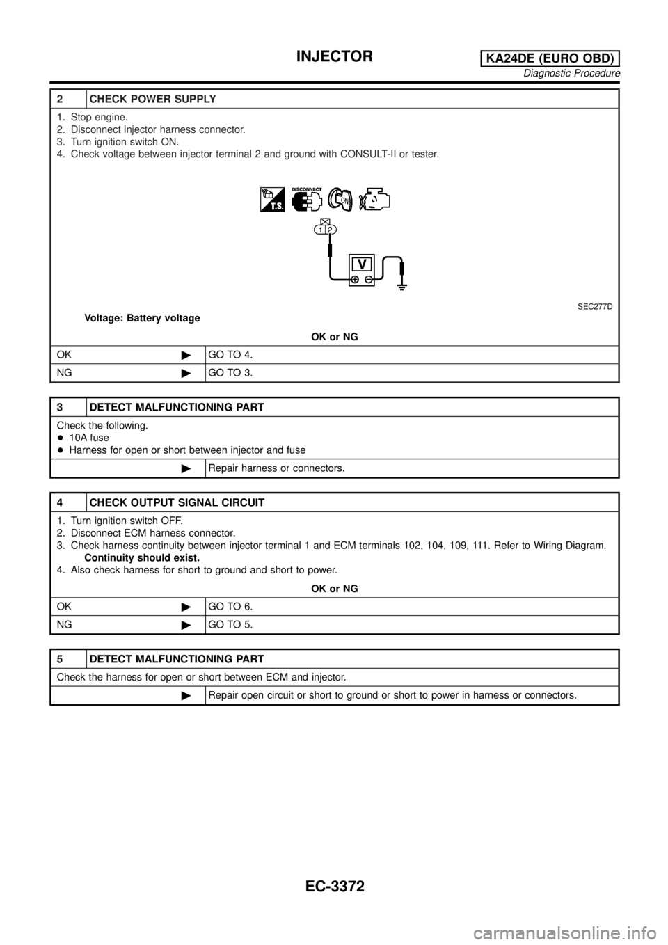
2 CHECK POWER SUPPLY
1. Stop engine.
2. Disconnect injector harness connector.
3. Turn ignition switch ON.
4. Check voltage between injector terminal 2 and ground with CONSULT-II or tester.
SEC277D
Voltage: Battery voltage
OK or NG
OK©GO TO 4.
NG©GO TO 3.
3 DETECT MALFUNCTIONING PART
Check the following.
+10A fuse
+Harness for open or short between injector and fuse
©Repair harness or connectors.
4 CHECK OUTPUT SIGNAL CIRCUIT
1. Turn ignition switch OFF.
2. Disconnect ECM harness connector.
3. Check harness continuity between injector terminal 1 and ECM terminals 102, 104, 109, 111. Refer to Wiring Diagram.
Continuity should exist.
4. Also check harness for short to ground and short to power.
OK or NG
OK©GO TO 6.
NG©GO TO 5.
5 DETECT MALFUNCTIONING PART
Check the harness for open or short between ECM and injector.
©Repair open circuit or short to ground or short to power in harness or connectors.
INJECTORKA24DE (EURO OBD)
Diagnostic Procedure
EC-3372
Page 398 of 1306
6 CHECK INJECTOR
1. Disconnect injector harness connector.
2. Check resistance between terminals as shown in the figure.
SEC278D
Resistance: 7.3 - 9.9W[at 25ÉC (77ÉF)]
OK or NG
OK©GO TO 7.
NG©Replace injector.
7 CHECK INTERMITTENT INCIDENT
Perform ªTROUBLE DIAGNOSIS FOR INTERMITTENT INCIDENTº, EC-3123.
©INSPECTION END
INJECTORKA24DE (EURO OBD)
Diagnostic Procedure
EC-3373
Page 399 of 1306
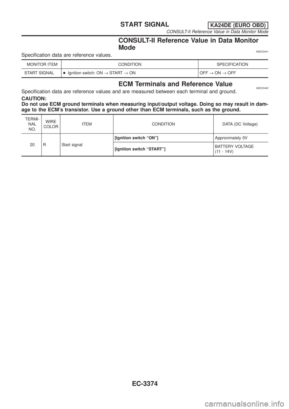
CONSULT-II Reference Value in Data Monitor
Mode
NEEC0441Specification data are reference values.
MONITOR ITEM CONDITION SPECIFICATION
START SIGNAL+Ignition switch: ON®START®ON OFF®ON®OFF
ECM Terminals and Reference ValueNEEC0442Specification data are reference values and are measured between each terminal and ground.
CAUTION:
Do not use ECM ground terminals when measuring input/output voltage. Doing so may result in dam-
age to the ECM's transistor. Use a ground other than ECM terminals, such as the ground.
TERMI-
NAL
NO.WIRE
COLORITEM CONDITION DATA (DC Voltage)
20 R Start signal[Ignition switch ªONº]Approximately 0V
[Ignition switch ªSTARTº]BATTERY VOLTAGE
(11 - 14V)
START SIGNALKA24DE (EURO OBD)
CONSULT-II Reference Value in Data Monitor Mode
EC-3374
Page 400 of 1306
Wiring DiagramNEEC0440
GEC255A
START SIGNALKA24DE (EURO OBD)
Wiring Diagram
EC-3375
Trending: auxiliary battery, service reset, towing, washer fluid, engine oil capacity, keyless entry, service indicator



![NISSAN PICK-UP 2001 Repair Manual 6 CHECK INJECTOR
1. Disconnect injector harness connector.
2. Check resistance between terminals as shown in the figure.
SEC278D
Resistance: 7.3 - 9.9W[at 25ÉC (77ÉF)]
OK or NG
OK©GO TO 7.
NG©Repl NISSAN PICK-UP 2001 Repair Manual 6 CHECK INJECTOR
1. Disconnect injector harness connector.
2. Check resistance between terminals as shown in the figure.
SEC278D
Resistance: 7.3 - 9.9W[at 25ÉC (77ÉF)]
OK or NG
OK©GO TO 7.
NG©Repl](/img/5/57372/w960_57372-397.png)
