NISSAN PICK-UP 2001 Repair Manual
Manufacturer: NISSAN, Model Year: 2001, Model line: PICK-UP, Model: NISSAN PICK-UP 2001Pages: 1306, PDF Size: 31.7 MB
Page 371 of 1306
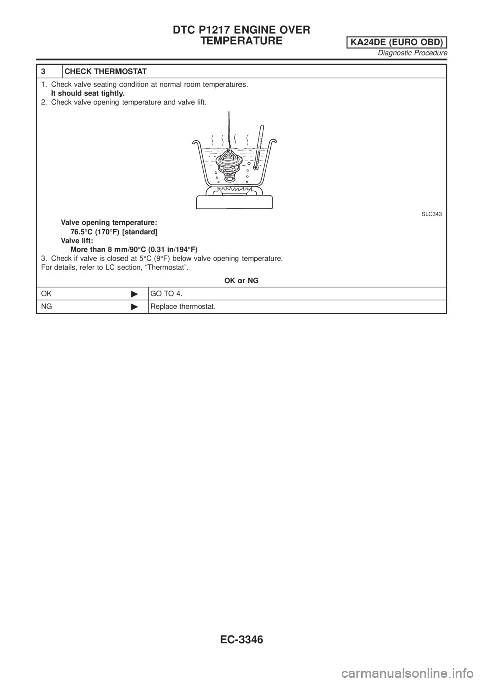
3 CHECK THERMOSTAT
1. Check valve seating condition at normal room temperatures.
It should seat tightly.
2. Check valve opening temperature and valve lift.
SLC343
Valve opening temperature:
76.5ÉC (170ÉF) [standard]
Valve lift:
More than 8 mm/90ÉC (0.31 in/194ÉF)
3. Check if valve is closed at 5ÉC (9ÉF) below valve opening temperature.
For details, refer to LC section, ªThermostatº.
OK or NG
OK©GO TO 4.
NG©Replace thermostat.
DTC P1217 ENGINE OVER
TEMPERATURE
KA24DE (EURO OBD)
Diagnostic Procedure
EC-3346
Page 372 of 1306

4 CHECK ENGINE COOLANT TEMPERATURE SENSOR
Check resistance as shown in the figure.
SEF152P
MTBL0285
SEF012P
OK or NG
OK©GO TO 5.
NG©Replace engine coolant temperature sensor.
5 CHECK MAIN 11 CAUSES
If the cause cannot be isolated, go to ªMAIN 11 CAUSES OF OVERHEATINGº, EC-3348.
©INSPECTION END
Perform FINAL CHECK by the following procedure after repair
is completed.
1. Warm up engine. Run the vehicle for at least 20 minutes. Pay
attention to engine coolant temperature gauge on the instru-
ment panel. If the reading shows an abnormally high
temperature, another part may be malfunctioning.
2. Stop vehicle and let engine idle. Check the intake and exhaust
systems for leaks by listening for noise or visually inspecting
the components.
3. Allow engine to cool and visually check for oil and coolant
leaks. Then, perform ªOVERALL FUNCTION CHECKº.
DTC P1217 ENGINE OVER
TEMPERATURE
KA24DE (EURO OBD)
Diagnostic Procedure
EC-3347
Page 373 of 1306
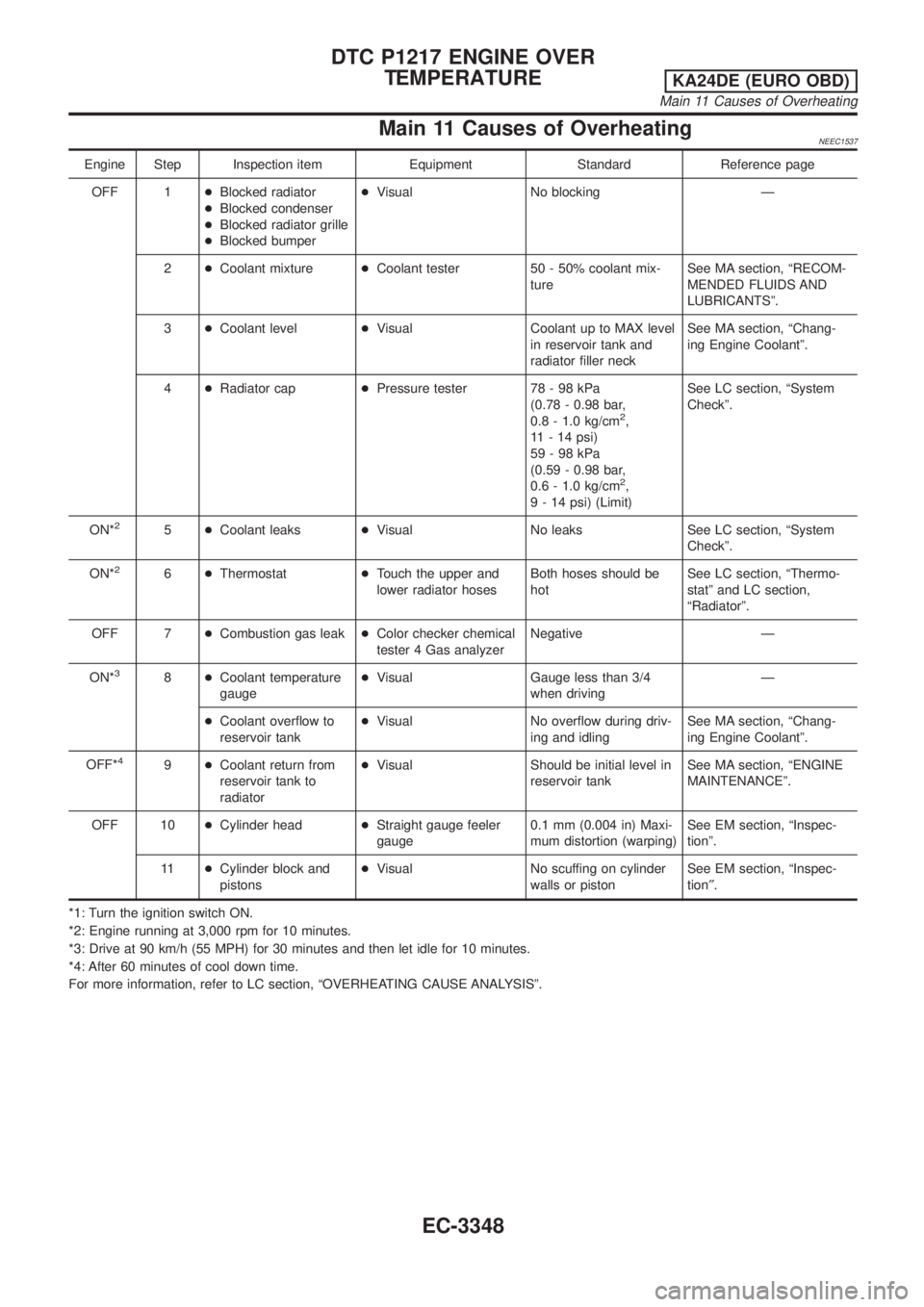
Main 11 Causes of OverheatingNEEC1537
Engine Step Inspection item Equipment Standard Reference page
OFF 1+Blocked radiator
+Blocked condenser
+Blocked radiator grille
+Blocked bumper+Visual No blocking Ð
2+Coolant mixture+Coolant tester 50 - 50% coolant mix-
tureSee MA section, ªRECOM-
MENDED FLUIDS AND
LUBRICANTSº.
3+Coolant level+Visual Coolant up to MAX level
in reservoir tank and
radiator filler neckSee MA section, ªChang-
ing Engine Coolantº.
4+Radiator cap+Pressure tester 78 - 98 kPa
(0.78 - 0.98 bar,
0.8 - 1.0 kg/cm
2,
11 - 14 psi)
59-98kPa
(0.59 - 0.98 bar,
0.6 - 1.0 kg/cm
2,
9 - 14 psi) (Limit)See LC section, ªSystem
Checkº.
ON*
25+Coolant leaks+Visual No leaks See LC section, ªSystem
Checkº.
ON*
26+Thermostat+Touch the upper and
lower radiator hosesBoth hoses should be
hotSee LC section, ªThermo-
statº and LC section,
ªRadiatorº.
OFF 7+Combustion gas leak+Color checker chemical
tester 4 Gas analyzerNegative Ð
ON*
38+Coolant temperature
gauge+Visual Gauge less than 3/4
when drivingÐ
+Coolant overflow to
reservoir tank+Visual No overflow during driv-
ing and idlingSee MA section, ªChang-
ing Engine Coolantº.
OFF*
49+Coolant return from
reservoir tank to
radiator+Visual Should be initial level in
reservoir tankSee MA section, ªENGINE
MAINTENANCEº.
OFF 10+Cylinder head+Straight gauge feeler
gauge0.1 mm (0.004 in) Maxi-
mum distortion (warping)See EM section, ªInspec-
tionº.
11+Cylinder block and
pistons+Visual No scuffing on cylinder
walls or pistonSee EM section, ªInspec-
tion².
*1: Turn the ignition switch ON.
*2: Engine running at 3,000 rpm for 10 minutes.
*3: Drive at 90 km/h (55 MPH) for 30 minutes and then let idle for 10 minutes.
*4: After 60 minutes of cool down time.
For more information, refer to LC section, ªOVERHEATING CAUSE ANALYSISº.
DTC P1217 ENGINE OVER
TEMPERATURE
KA24DE (EURO OBD)
Main 11 Causes of Overheating
EC-3348
Page 374 of 1306
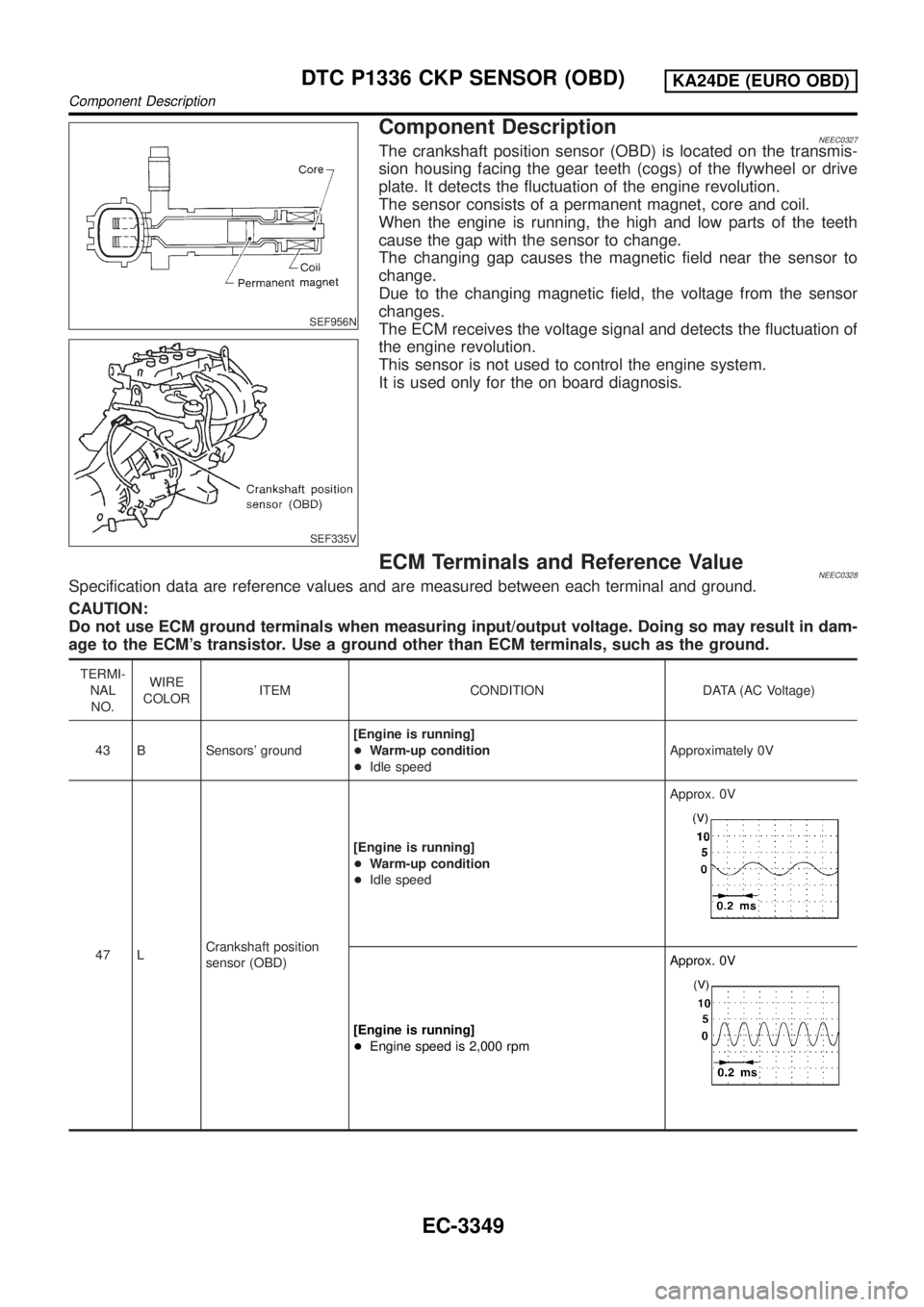
SEF956N
SEF335V
Component DescriptionNEEC0327The crankshaft position sensor (OBD) is located on the transmis-
sion housing facing the gear teeth (cogs) of the flywheel or drive
plate. It detects the fluctuation of the engine revolution.
The sensor consists of a permanent magnet, core and coil.
When the engine is running, the high and low parts of the teeth
cause the gap with the sensor to change.
The changing gap causes the magnetic field near the sensor to
change.
Due to the changing magnetic field, the voltage from the sensor
changes.
The ECM receives the voltage signal and detects the fluctuation of
the engine revolution.
This sensor is not used to control the engine system.
It is used only for the on board diagnosis.
ECM Terminals and Reference ValueNEEC0328Specification data are reference values and are measured between each terminal and ground.
CAUTION:
Do not use ECM ground terminals when measuring input/output voltage. Doing so may result in dam-
age to the ECM's transistor. Use a ground other than ECM terminals, such as the ground.
TERMI-
NAL
NO.WIRE
COLORITEM CONDITION DATA (AC Voltage)
43 B Sensors' ground[Engine is running]
+Warm-up condition
+Idle speedApproximately 0V
47 LCrankshaft position
sensor (OBD)[Engine is running]
+Warm-up condition
+Idle speedApprox. 0V
[Engine is running]
+Engine speed is 2,000 rpmApprox. 0V
DTC P1336 CKP SENSOR (OBD)KA24DE (EURO OBD)
Component Description
EC-3349
Page 375 of 1306
On Board Diagnosis LogicNEEC0329
DTC No. Malfunction is detected when ... Check Items (Possible Cause)
P1336
1336+A chipping of the flywheel or drive plate gear tooth (cog)
is detected by the ECM.+Harness or connectors
+Crankshaft position sensor (OBD)
+Flywheel
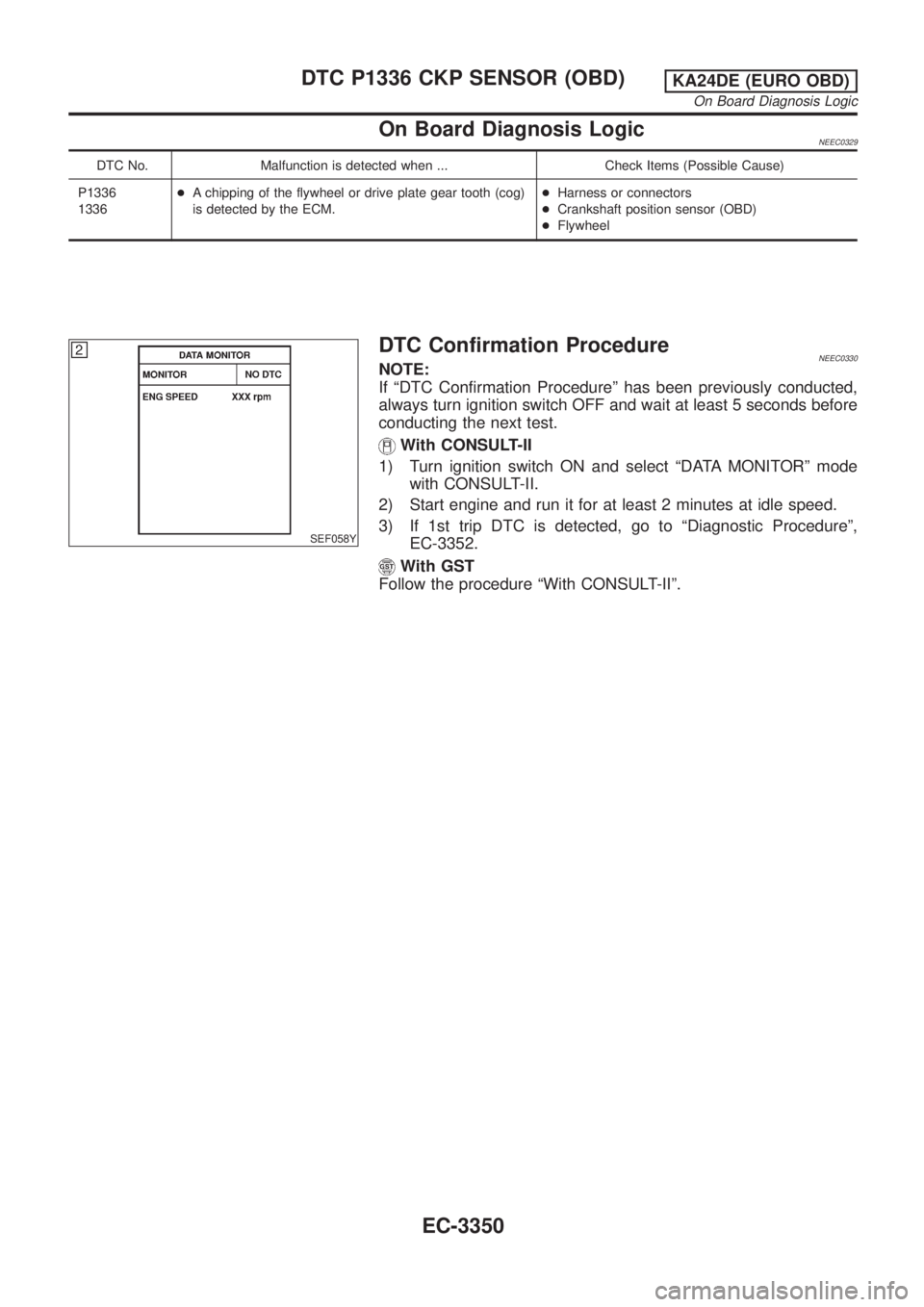
SEF058Y
DTC Confirmation ProcedureNEEC0330NOTE:
If ªDTC Confirmation Procedureº has been previously conducted,
always turn ignition switch OFF and wait at least 5 seconds before
conducting the next test.
With CONSULT-II
1) Turn ignition switch ON and select ªDATA MONITORº mode
with CONSULT-II.
2) Start engine and run it for at least 2 minutes at idle speed.
3) If 1st trip DTC is detected, go to ªDiagnostic Procedureº,
EC-3352.
With GST
Follow the procedure ªWith CONSULT-IIº.
DTC P1336 CKP SENSOR (OBD)KA24DE (EURO OBD)
On Board Diagnosis Logic
EC-3350
Page 376 of 1306

Wiring DiagramNEEC0331
GEC236A
DTC P1336 CKP SENSOR (OBD)KA24DE (EURO OBD)
Wiring Diagram
EC-3351
Page 377 of 1306
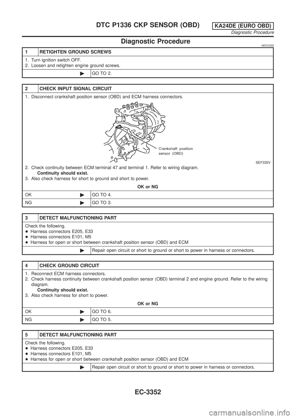
Diagnostic ProcedureNEEC0332
1 RETIGHTEN GROUND SCREWS
1. Turn ignition switch OFF.
2. Loosen and retighten engine ground screws.
©GO TO 2.
2 CHECK INPUT SIGNAL CIRCUIT
1. Disconnect crankshaft position sensor (OBD) and ECM harness connectors.
SEF335V
2. Check continuity between ECM terminal 47 and terminal 1. Refer to wiring diagram.
Continuity should exist.
3. Also check harness for short to ground and short to power.
OK or NG
OK©GO TO 4.
NG©GO TO 3.
3 DETECT MALFUNCTIONING PART
Check the following.
+Harness connectors E205, E33
+Harness connectors E101, M5
+Harness for open or short between crankshaft position sensor (OBD) and ECM
©Repair open circuit or short to ground or short to power in harness or connectors.
4 CHECK GROUND CIRCUIT
1. Reconnect ECM harness connectors.
2. Check harness continuity between crankshaft position sensor (OBD) terminal 2 and engine ground. Refer to the wiring
diagram.
Continuity should exist.
3. Also check harness for short to power.
OK or NG
OK©GO TO 6.
NG©GO TO 5.
5 DETECT MALFUNCTIONING PART
Check the following.
+Harness connectors E205, E33
+Harness connectors E101, M5
+Harness for open or short between crankshaft position sensor (OBD) and ECM
©Repair open circuit or short to ground or short to power in harness or connectors.
DTC P1336 CKP SENSOR (OBD)KA24DE (EURO OBD)
Diagnostic Procedure
EC-3352
Page 378 of 1306
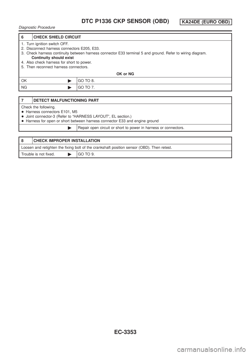
6 CHECK SHIELD CIRCUIT
1. Turn ignition switch OFF.
2. Disconnect harness connectors E205, E33.
3. Check harness continuity between harness connector E33 terminal 5 and ground. Refer to wiring diagram.
Continuity should exist
4. Also check harness for short to power.
5. Then reconnect harness connectors.
OK or NG
OK©GO TO 8.
NG©GO TO 7.
7 DETECT MALFUNCTIONING PART
Check the following.
+Harness connectors E101, M5
+Joint connector-3 (Refer to ªHARNESS LAYOUTº, EL section.)
+Harness for open or short between harness connector E33 and engine ground
©Repair open circuit or short to power in harness or connectors.
8 CHECK IMPROPER INSTALLATION
Loosen and retighten the fixing bolt of the crankshaft position sensor (OBD). Then retest.
Trouble is not fixed.©GO TO 9.
DTC P1336 CKP SENSOR (OBD)KA24DE (EURO OBD)
Diagnostic Procedure
EC-3353
Page 379 of 1306
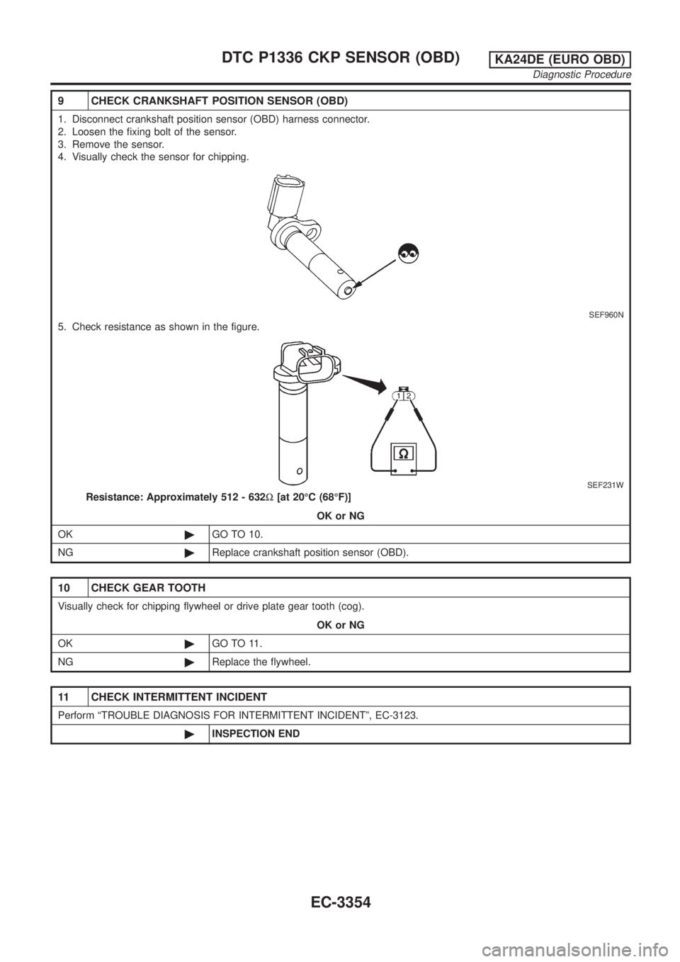
9 CHECK CRANKSHAFT POSITION SENSOR (OBD)
1. Disconnect crankshaft position sensor (OBD) harness connector.
2. Loosen the fixing bolt of the sensor.
3. Remove the sensor.
4. Visually check the sensor for chipping.
SEF960N
5. Check resistance as shown in the figure.
SEF231W
Resistance: Approximately 512 - 632W[at 20ÉC (68ÉF)]
OK or NG
OK©GO TO 10.
NG©Replace crankshaft position sensor (OBD).
10 CHECK GEAR TOOTH
Visually check for chipping flywheel or drive plate gear tooth (cog).
OK or NG
OK©GO TO 11.
NG©Replace the flywheel.
11 CHECK INTERMITTENT INCIDENT
Perform ªTROUBLE DIAGNOSIS FOR INTERMITTENT INCIDENTº, EC-3123.
©INSPECTION END
DTC P1336 CKP SENSOR (OBD)KA24DE (EURO OBD)
Diagnostic Procedure
EC-3354
Page 380 of 1306
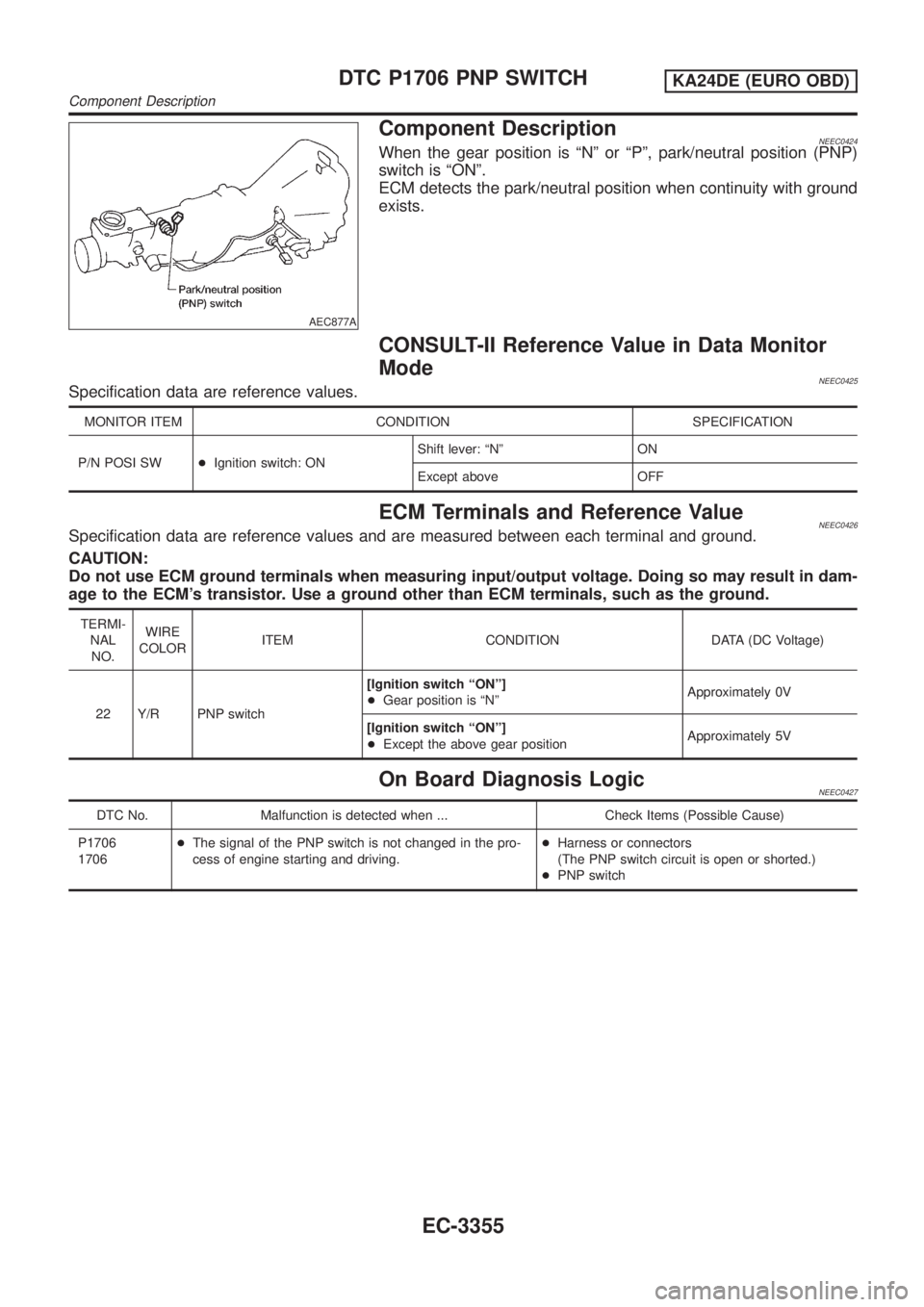
AEC877A
Component DescriptionNEEC0424When the gear position is ªNº or ªPº, park/neutral position (PNP)
switch is ªONº.
ECM detects the park/neutral position when continuity with ground
exists.
CONSULT-II Reference Value in Data Monitor
Mode
NEEC0425Specification data are reference values.
MONITOR ITEM CONDITION SPECIFICATION
P/N POSI SW+Ignition switch: ONShift lever: ªNº ON
Except above OFF
ECM Terminals and Reference ValueNEEC0426Specification data are reference values and are measured between each terminal and ground.
CAUTION:
Do not use ECM ground terminals when measuring input/output voltage. Doing so may result in dam-
age to the ECM's transistor. Use a ground other than ECM terminals, such as the ground.
TERMI-
NAL
NO.WIRE
COLORITEM CONDITION DATA (DC Voltage)
22 Y/R PNP switch[Ignition switch ªONº]
+Gear position is ªNºApproximately 0V
[Ignition switch ªONº]
+Except the above gear positionApproximately 5V
On Board Diagnosis LogicNEEC0427
DTC No. Malfunction is detected when ... Check Items (Possible Cause)
P1706
1706+The signal of the PNP switch is not changed in the pro-
cess of engine starting and driving.+Harness or connectors
(The PNP switch circuit is open or shorted.)
+PNP switch
DTC P1706 PNP SWITCHKA24DE (EURO OBD)
Component Description
EC-3355