NISSAN PRIMERA 1999 Electronic Repair Manual
Manufacturer: NISSAN, Model Year: 1999, Model line: PRIMERA, Model: NISSAN PRIMERA 1999Pages: 2267, PDF Size: 35.74 MB
Page 191 of 2267
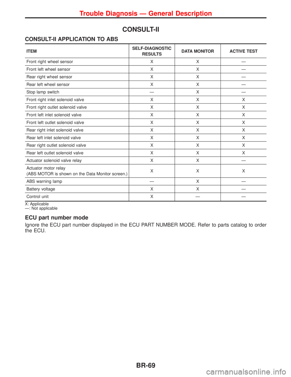
CONSULT-II
CONSULT-II APPLICATION TO ABS
ITEMSELF-DIAGNOSTIC
RESULTSDATA MONITOR ACTIVE TEST
Front right wheel sensor X X Ð
Front left wheel sensor X X Ð
Rear right wheel sensor X X Ð
Rear left wheel sensor X X Ð
Stop lamp switch Ð X Ð
Front right inlet solenoid valve X X X
Front right outlet solenoid valve X X X
Front left inlet solenoid valve X X X
Front left outlet solenoid valve X X X
Rear right inlet solenoid valve X X X
Rear left inlet solenoid valve X X X
Rear right outlet solenoid valve X X X
Rear left outlet solenoid valve X X X
Actuator solenoid valve relay X X Ð
Actuator motor relay
(ABS MOTOR is shown on the Data Monitor screen.)XXX
ABS warning lamp Ð X Ð
Battery voltage X X Ð
Control unit X Ð Ð
X: Applicable
Ð: Not applicable
ECU part number mode
Ignore the ECU part number displayed in the ECU PART NUMBER MODE. Refer to parts catalog to order
the ECU.
Trouble Diagnosis Ð General Description
BR-69
Page 192 of 2267
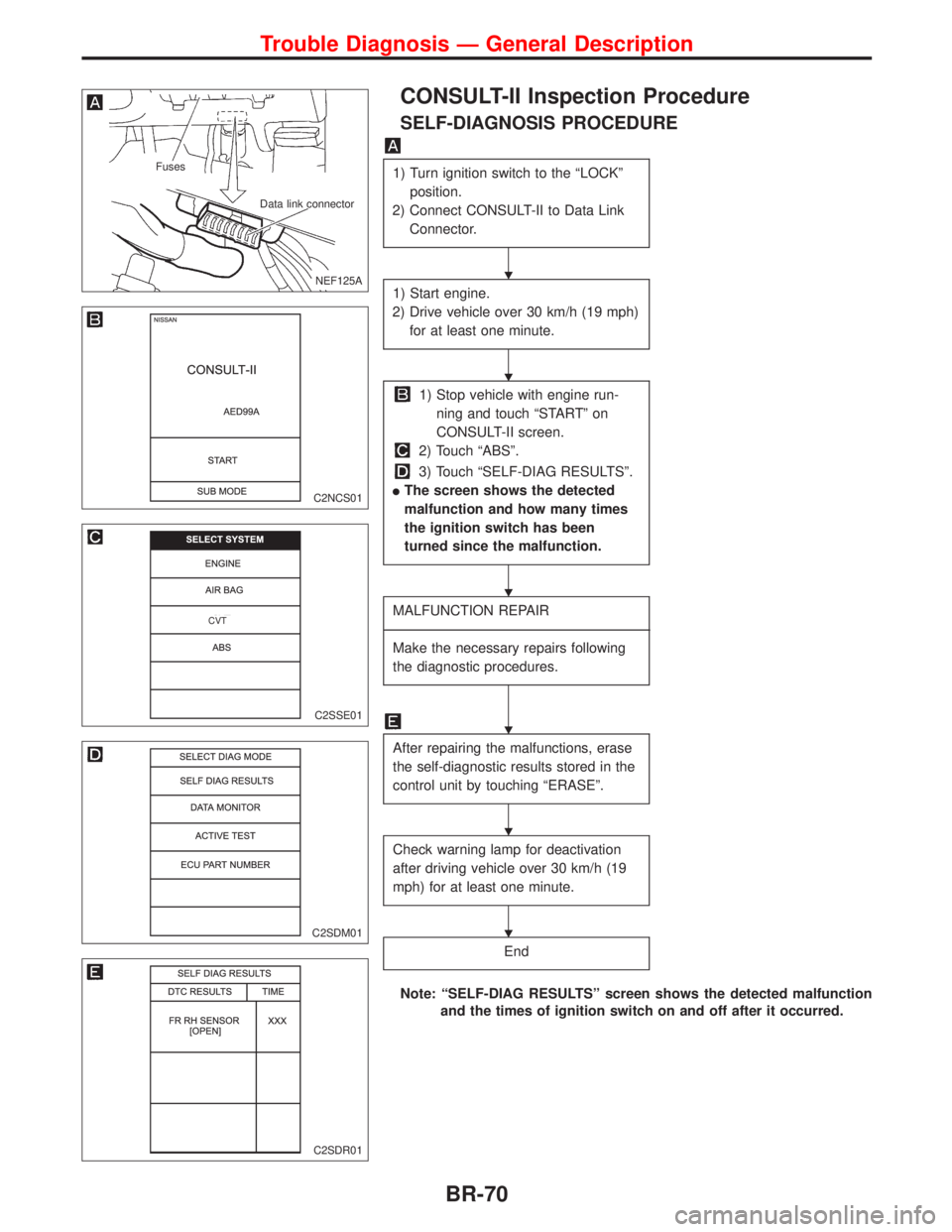
CONSULT-II Inspection Procedure
SELF-DIAGNOSIS PROCEDURE
1) Turn ignition switch to the ªLOCKº
position.
2) Connect CONSULT-II to Data Link
Connector.
1) Start engine.
2) Drive vehicle over 30 km/h (19 mph)
for at least one minute.
1) Stop vehicle with engine run-
ning and touch ªSTARTº on
CONSULT-II screen.
2) Touch ªABSº.
3) Touch ªSELF-DIAG RESULTSº.
lThe screen shows the detected
malfunction and how many times
the ignition switch has been
turned since the malfunction.
MALFUNCTION REPAIR
----------------------------------------------------------------------------------------------------------------------------------------------------------------------------------------------------------------------------------------------------------------------------------------------------------
Make the necessary repairs following
the diagnostic procedures.
After repairing the malfunctions, erase
the self-diagnostic results stored in the
control unit by touching ªERASEº.
Check warning lamp for deactivation
after driving vehicle over 30 km/h (19
mph) for at least one minute.
End
Note: ªSELF-DIAG RESULTSº screen shows the detected malfunction
and the times of ignition switch on and off after it occurred.
.NEF125A
Fuses
Data link connector
C2NCS01
C2SSE01
.CVT
C2SDM01
C2SDR01
H
H
H
H
H
H
Trouble Diagnosis Ð General Description
BR-70
Page 193 of 2267
![NISSAN PRIMERA 1999 Electronic Repair Manual SELF-DIAGNOSTIC RESULTS MODE
Diagnostic item Diagnostic item is detected when...Diagnostic
procedure
FR RH SENSORH
[OPEN]
lCircuit for front right wheel sensor is open.
(An abnormally high input volta NISSAN PRIMERA 1999 Electronic Repair Manual SELF-DIAGNOSTIC RESULTS MODE
Diagnostic item Diagnostic item is detected when...Diagnostic
procedure
FR RH SENSORH
[OPEN]
lCircuit for front right wheel sensor is open.
(An abnormally high input volta](/img/5/57377/w960_57377-192.png)
SELF-DIAGNOSTIC RESULTS MODE
Diagnostic item Diagnostic item is detected when...Diagnostic
procedure
FR RH SENSORH
[OPEN]
lCircuit for front right wheel sensor is open.
(An abnormally high input voltage is entered.)1
FR LH SENSORH
[OPEN]
lCircuit for front left wheel sensor is open.
(An abnormally high input voltage is entered.)1
RR RH SENSORH
[OPEN]
lCircuit for rear right sensor is open.
(An abnormally high input voltage is entered.)1
RR LH SENSORH
[OPEN]
lCircuit for rear left sensor is open.
(An abnormally high input voltage is entered.)1
FR RH SENSORH
[SHORT]
lCircuit for front right wheel sensor is shorted.
(An abnormally low input voltage is entered.)1
FR LH SENSORH
[SHORT]
lCircuit for front left wheel sensor is shorted.
(An abnormally low input voltage is entered.)1
RR RH SENSORH
[SHORT]
lCircuit for rear right sensor is shorted.
(An abnormally low input voltage is entered.)1
RR LH SENSOR
[SHORT]
lCircuit for rear left sensor is shorted.
(An abnormally low input voltage is entered.)1
ABS SENSORH
[ABNORMAL SIGNAL]
lTeeth damage on sensor rotor or improper installation of wheel sensor.
(Abnormal wheel sensor signal is entered.)1
FR RH IN ABS SOL
[OPEN]
lCircuit for front right inlet solenoid valve is open.
(An abnormally low output voltage is entered.)2
FR LH IN ABS SOL
[OPEN]
lCircuit for front left inlet solenoid valve is open.
(An abnormally low output voltage is entered.)2
RR RH IN ABS SOL
[OPEN]
lCircuit for rear right inlet solenoid valve is open.
(An abnormally low output voltage is entered.)2
RR LH IN ABS SOL
[OPEN]
lCircuit for rear left inlet solenoid valve is open.
(An abnormally low output voltage is entered.)2
FR RH IN ABS SOL
[SHORT]
lCircuit for front right inlet solenoid valve is shorted.
(An abnormally high output voltage is entered.)2
FR LH IN ABS SOL
[SHORT]
lCircuit for front left inlet solenoid valve is shorted.
(An abnormally high output voltage is entered.)2
RR RH IN ABS SOL
[SHORT]
lCircuit for rear right inlet solenoid valve is shorted.
(An abnormally high output voltage is entered.)2
RR LH IN ABS SOL
[SHORT]
lCircuit for rear left inlet solenoid valve is shorted.
(An abnormally high output voltage is entered.)2
FR RH OUT ABS SOL
[OPEN]
lCircuit for front right outlet solenoid valve is open.
(An abnormally low output voltage is entered.)2
FR LH OUT ABS SOL
[OPEN]
lCircuit for front left outlet solenoid valve is open.
(An abnormally low output voltage is entered.)2
RR RH OUT ABS SOL
[OPEN]
lCircuit for rear right outlet solenoid valve is open.
(An abnormally low output voltage is entered.)2
RR LH OUT ABS SOL
[OPEN]
lCircuit for rear left outlet solenoid valve is open.
(An abnormally low output voltage is entered.)2
FR RH OUT ABS SOL
[SHORT]
lCircuit for front right outlet solenoid valve is shorted.
(An abnormally high output voltage is entered.)2
FR LH OUT ABS SOL
[SHORT]
lCircuit for front left outlet solenoid valve is shorted.
(An abnormally high output voltage is entered.)2
RR RH OUT ABS SOL
[SHORT]
lCircuit for rear right outlet solenoid valve is shorted.
(An abnormally high output voltage is entered.)2
RR LH OUT ABS SOL
[SHORT]
lCircuit for rear left outlet solenoid valve is shorted.
(An abnormally high output voltage is entered.)2
ABS ACTUATOR RELAY
[ABNORMAL]
lActuator solenoid valve relay is ON, even control unit sends off signal.lActuator solenoid valve relay is OFF, even control unit sends on signal.2
ABS MOTOR RELAY
[ABNORMAL]
lCircuit for actuator motor is open or shorted.lActuator motor relay is stuck.lCircuit for actuator is open or shorted.3
BATTERY VOLT
[VB-LOW]
lPower source voltage supplied to ABS control unit is abnormally low. 4
CONTROL UNIT
lFunction of calculation in ABS control unit has failed. 5
H: If one or more wheels spin on a rough or slippery road for 40 seconds or more, the ABS warning lamp will illuminate. This does
not indicate a malfunction. Only in the case of the short-circuit after repair the ABS warning lamp also illuminates when the igni-
tion switch is turned ªONº. In this case, drive the vehicle at speeds greater than 30 km/h (19 MPH) for approximately 1 minute
as specified in ªSELF-DIAGNOSIS PROCEDUREº, BR-70. Check to ensure that the ABS warning lamp goes out while the
vehicle is being driven.
Trouble Diagnosis Ð General Description
CONSULT-II Inspection Procedure (Cont'd)
BR-71
Page 194 of 2267
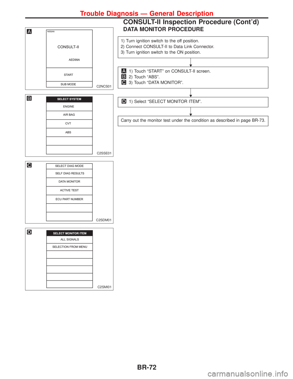
DATA MONITOR PROCEDURE
1) Turn ignition switch to the off position.
2) Connect CONSULT-II to Data Link Connector.
3) Turn ignition switch to the ON position.
1) Touch ªSTARTº on CONSULT-II screen.
2) Touch ªABSº.
3) Touch ªDATA MONITORº.
1) Select ªSELECT MONITOR ITEMº.
Carry out the monitor test under the condition as described in page BR-73.
C2NCS01
C2SSE01
C2SDM01
C2SMI01
H
H
H
Trouble Diagnosis Ð General Description
CONSULT-II Inspection Procedure (Cont'd)
BR-72
Page 195 of 2267
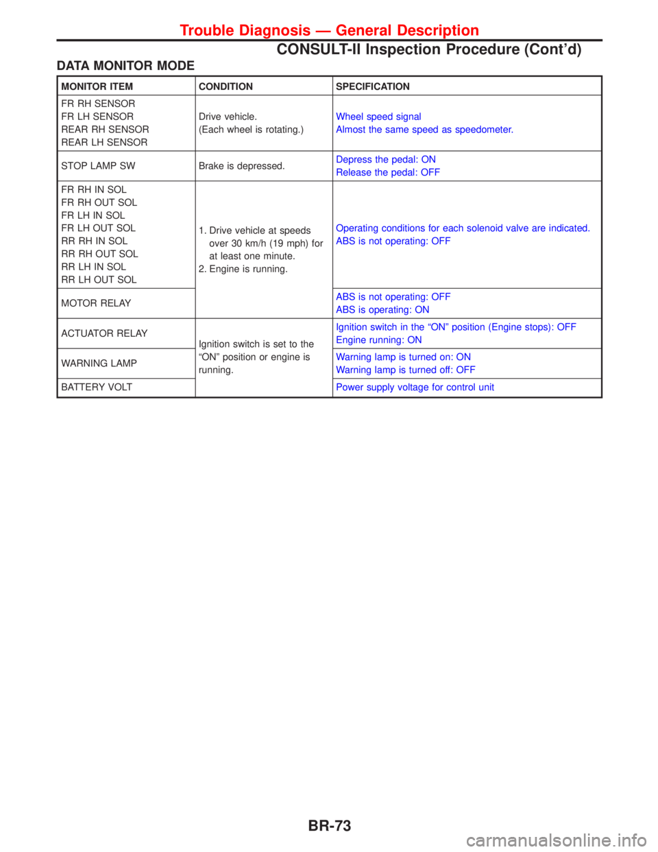
DATA MONITOR MODE
MONITOR ITEM CONDITION SPECIFICATION
FR RH SENSOR
FR LH SENSOR
REAR RH SENSOR
REAR LH SENSORDrive vehicle.
(Each wheel is rotating.)Wheel speed signal
Almost the same speed as speedometer.
STOP LAMP SW Brake is depressed.Depress the pedal: ON
Release the pedal: OFF
FR RH IN SOL
FR RH OUT SOL
FR LH IN SOL
FR LH OUT SOL
RR RH IN SOL
RR RH OUT SOL
RR LH IN SOL
RR LH OUT SOL1. Drive vehicle at speeds
over 30 km/h (19 mph) for
at least one minute.
2. Engine is running.Operating conditions for each solenoid valve are indicated.
ABS is not operating: OFF
MOTOR RELAYABS is not operating: OFF
ABS is operating: ON
ACTUATOR RELAY
Ignition switch is set to the
ªONº position or engine is
running.Ignition switch in the ªONº position (Engine stops): OFF
Engine running: ON
WARNING LAMPWarning lamp is turned on: ON
Warning lamp is turned off: OFF
BATTERY VOLTPower supply voltage for control unit
Trouble Diagnosis Ð General Description
CONSULT-II Inspection Procedure (Cont'd)
BR-73
Page 196 of 2267
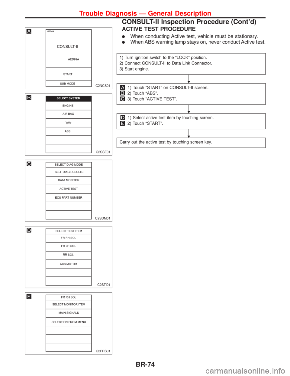
ACTIVE TEST PROCEDURE
lWhen conducting Active test, vehicle must be stationary.
lWhen ABS warning lamp stays on, never conduct Active test.
1) Turn ignition switch to the ªLOCKº position.
2) Connect CONSULT-II to Data Link Connector.
3) Start engine.
1) Touch ªSTARTº on CONSULT-II screen.
2) Touch ªABSº.
3) Touch ªACTIVE TESTº.
1) Select active test item by touching screen.
2) Touch ªSTARTº.
Carry out the active test by touching screen key.
C2NCS01
C2SSE01
.CVT
C2SDM01
C2STI01
C2FRS01
H
H
H
Trouble Diagnosis Ð General Description
CONSULT-II Inspection Procedure (Cont'd)
BR-74
Page 197 of 2267
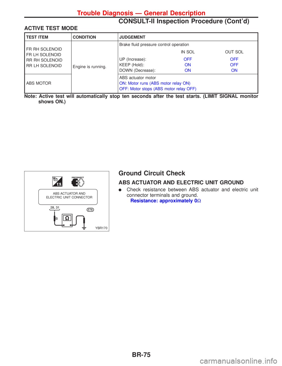
ACTIVE TEST MODE
TEST ITEM CONDITION JUDGEMENT
FR RH SOLENOID
FR LH SOLENOID
RR RH SOLENOID
RR LH SOLENOID
Engine is running.Brake fluid pressure control operation
IN SOL OUT SOL
UP (Increase):
KEEP (Hold):
DOWN (Decrease):OFF
ON
ONOFF
OFF
ON
ABS MOTORABS actuator motor
ON: Motor runs (ABS motor relay ON)
OFF: Motor stops (ABS motor relay OFF)
Note: Active test will automatically stop ten seconds after the test starts. (LIMIT SIGNAL monitor
shows ON.)
Ground Circuit Check
ABS ACTUATOR AND ELECTRIC UNIT GROUND
lCheck resistance between ABS actuator and electric unit
connector terminals and ground.
Resistance: approximately 0W
YBR170 ABS ACTUATOR AND
ELECTRIC UNIT CONNECTOR
Trouble Diagnosis Ð General Description
CONSULT-II Inspection Procedure (Cont'd)
BR-75
Page 198 of 2267
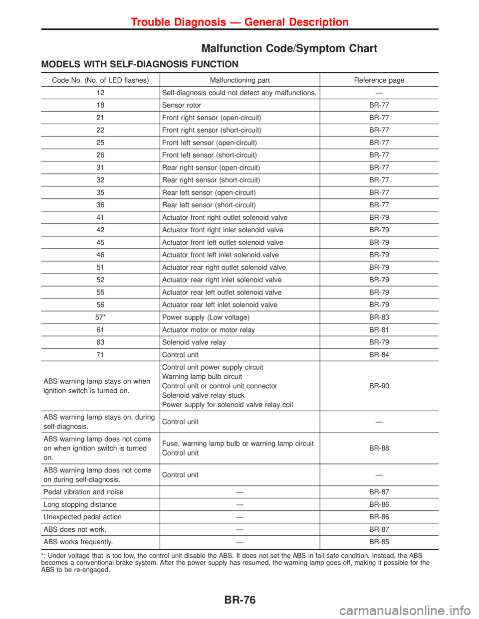
Malfunction Code/Symptom Chart
MODELS WITH SELF-DIAGNOSIS FUNCTION
Code No. (No. of LED flashes) Malfunctioning part Reference page
12 Self-diagnosis could not detect any malfunctions. Ð
18 Sensor rotor BR-77
21 Front right sensor (open-circuit) BR-77
22 Front right sensor (short-circuit) BR-77
25 Front left sensor (open-circuit) BR-77
26 Front left sensor (short-circuit) BR-77
31 Rear right sensor (open-circuit) BR-77
32 Rear right sensor (short-circuit) BR-77
35 Rear left sensor (open-circuit) BR-77
36 Rear left sensor (short-circuit) BR-77
41 Actuator front right outlet solenoid valve BR-79
42 Actuator front right inlet solenoid valve BR-79
45 Actuator front left outlet solenoid valve BR-79
46 Actuator front left inlet solenoid valve BR-79
51 Actuator rear right outlet solenoid valve BR-79
52 Actuator rear right inlet solenoid valve BR-79
55 Actuator rear left outlet solenoid valve BR-79
56 Actuator rear left inlet solenoid valve BR-79
57* Power supply (Low voltage) BR-83
61 Actuator motor or motor relay BR-81
63 Solenoid valve relay BR-79
71 Control unit BR-84
ABS warning lamp stays on when
ignition switch is turned on.Control unit power supply circuit
Warning lamp bulb circuit
Control unit or control unit connector
Solenoid valve relay stuck
Power supply for solenoid valve relay coilBR-90
ABS warning lamp stays on, during
self-diagnosis.Control unit Ð
ABS warning lamp does not come
on when ignition switch is turned
on.Fuse, warning lamp bulb or warning lamp circuit
Control unitBR-88
ABS warning lamp does not come
on during self-diagnosis.Control unit Ð
Pedal vibration and noise Ð BR-87
Long stopping distance Ð BR-86
Unexpected pedal action Ð BR-86
ABS does not work. Ð BR-87
ABS works frequently. Ð BR-85
*: Under voltage that is too low, the control unit disable the ABS. It does not set the ABS in fail-safe condition. Instead, the ABS
becomes a conventional brake system. After the power supply has resumed, the warning lamp goes off, making it possible for the
ABS to be re-engaged.
Trouble Diagnosis Ð General Description
BR-76
Page 199 of 2267
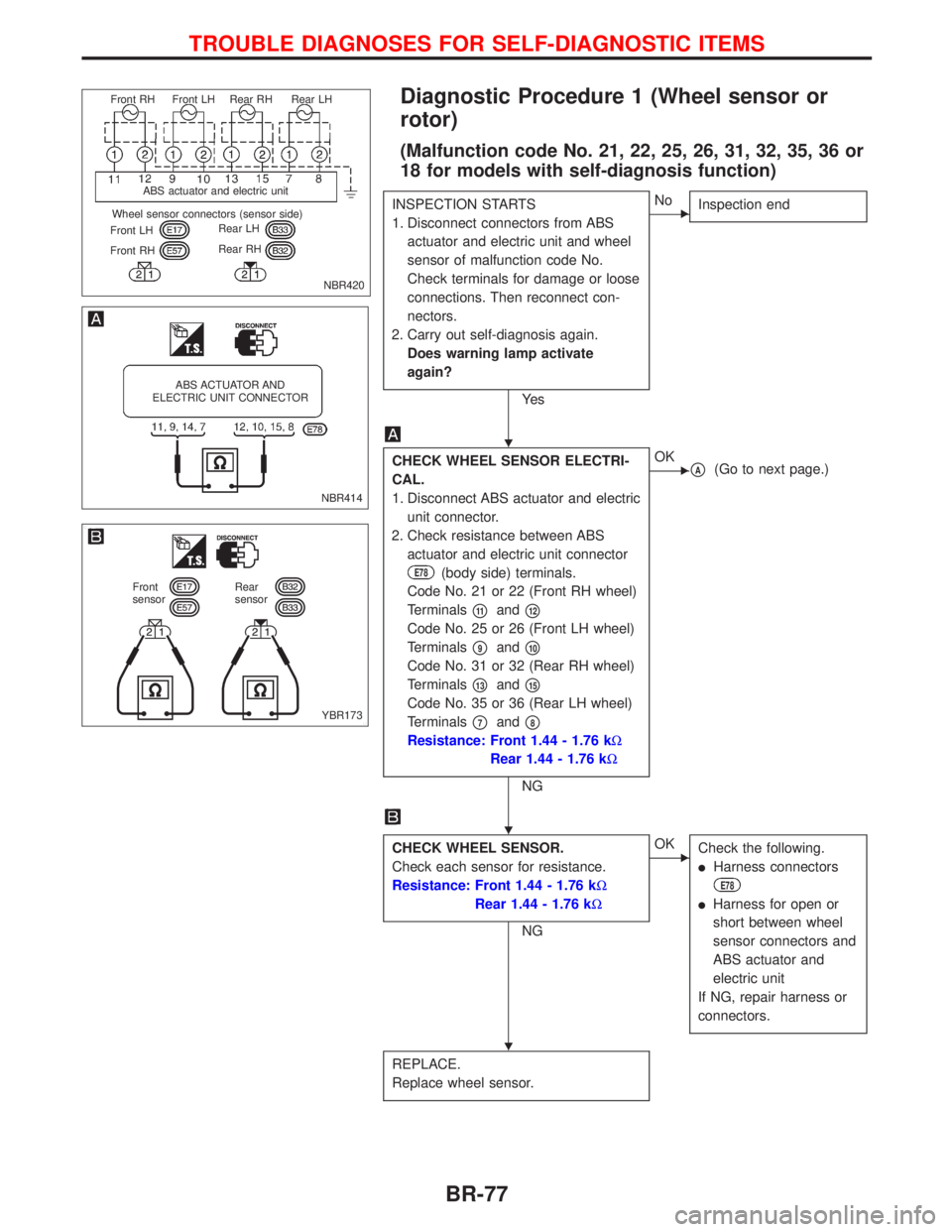
Diagnostic Procedure 1 (Wheel sensor or
rotor)
(Malfunction code No. 21, 22, 25, 26, 31, 32, 35, 36 or
18 for models with self-diagnosis function)
INSPECTION STARTS
1. Disconnect connectors from ABS
actuator and electric unit and wheel
sensor of malfunction code No.
Check terminals for damage or loose
connections. Then reconnect con-
nectors.
2. Carry out self-diagnosis again.
Does warning lamp activate
again?
Ye s
ENo
Inspection end
CHECK WHEEL SENSOR ELECTRI-
CAL.
1. Disconnect ABS actuator and electric
unit connector.
2. Check resistance between ABS
actuator and electric unit connector
E78(body side) terminals.
Code No. 21 or 22 (Front RH wheel)
Terminals
p11andp12
Code No. 25 or 26 (Front LH wheel)
Terminals
p9andp10
Code No. 31 or 32 (Rear RH wheel)
Terminals
p13andp15
Code No. 35 or 36 (Rear LH wheel)
Terminals
p7andp8
Resistance: Front 1.44 - 1.76 kW
Rear 1.44 - 1.76 kW
NG
EOKpA(Go to next page.)
CHECK WHEEL SENSOR.
Check each sensor for resistance.
Resistance: Front 1.44 - 1.76 kW
Rear 1.44 - 1.76 kW
NG
EOK
Check the following.
lHarness connectors
E78
lHarness for open or
short between wheel
sensor connectors and
ABS actuator and
electric unit
If NG, repair harness or
connectors.
REPLACE.
Replace wheel sensor.
NBR420 Front RH Front LH Rear RH Rear LH
ABS actuator and electric unit
Wheel sensor connectors (sensor side)
Front LH
Front RHRear LH
Rear RH
NBR414
ABS ACTUATOR AND
ELECTRIC UNIT CONNECTOR
YBR173
Front
sensorRear
sensor
H
H
H
TROUBLE DIAGNOSES FOR SELF-DIAGNOSTIC ITEMS
BR-77
Page 200 of 2267
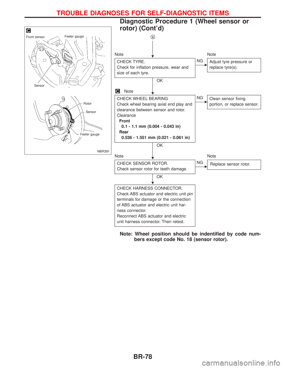
pA
Note Note
CHECK TYRE.
Check for inflation pressure, wear and
size of each tyre.
OK
ENG
Adjust tyre pressure or
replace tyre(s).
Note
CHECK WHEEL BEARING
Check wheel bearing axial end play and
clearance between sensor and rotor.
Clearance
Front
0.1 - 1.1 mm (0.004 - 0.043 in)
Rear
0.536 - 1.551 mm (0.021 - 0.061 in)
OK
ENG
Clean sensor fixing
portion, or replace sensor.
Note Note
CHECK SENSOR ROTOR.
Check sensor rotor for teeth damage.
OK
ENG
Replace sensor rotor.
CHECK HARNESS CONNECTOR.
Check ABS actuator and electric unit pin
terminals for damage or the connection
of ABS actuator and electric unit har-
ness connector.
Reconnect ABS actuator and electric
unit harness connector. Then retest.
Note: Wheel position should be indentified by code num-
bers except code No. 18 (sensor rotor).
NBR391
Front sensorFeeler gauge
Sensor
Rotor
Sensor
Feeler gauge
H
H
H
H
TROUBLE DIAGNOSES FOR SELF-DIAGNOSTIC ITEMS
Diagnostic Procedure 1 (Wheel sensor or
rotor) (Cont'd)
BR-78