low oil pressure NISSAN PRIMERA 1999 Electronic Owner's Manual
[x] Cancel search | Manufacturer: NISSAN, Model Year: 1999, Model line: PRIMERA, Model: NISSAN PRIMERA 1999Pages: 2267, PDF Size: 35.74 MB
Page 823 of 2267
Multiport Fuel Injection (MFI) System
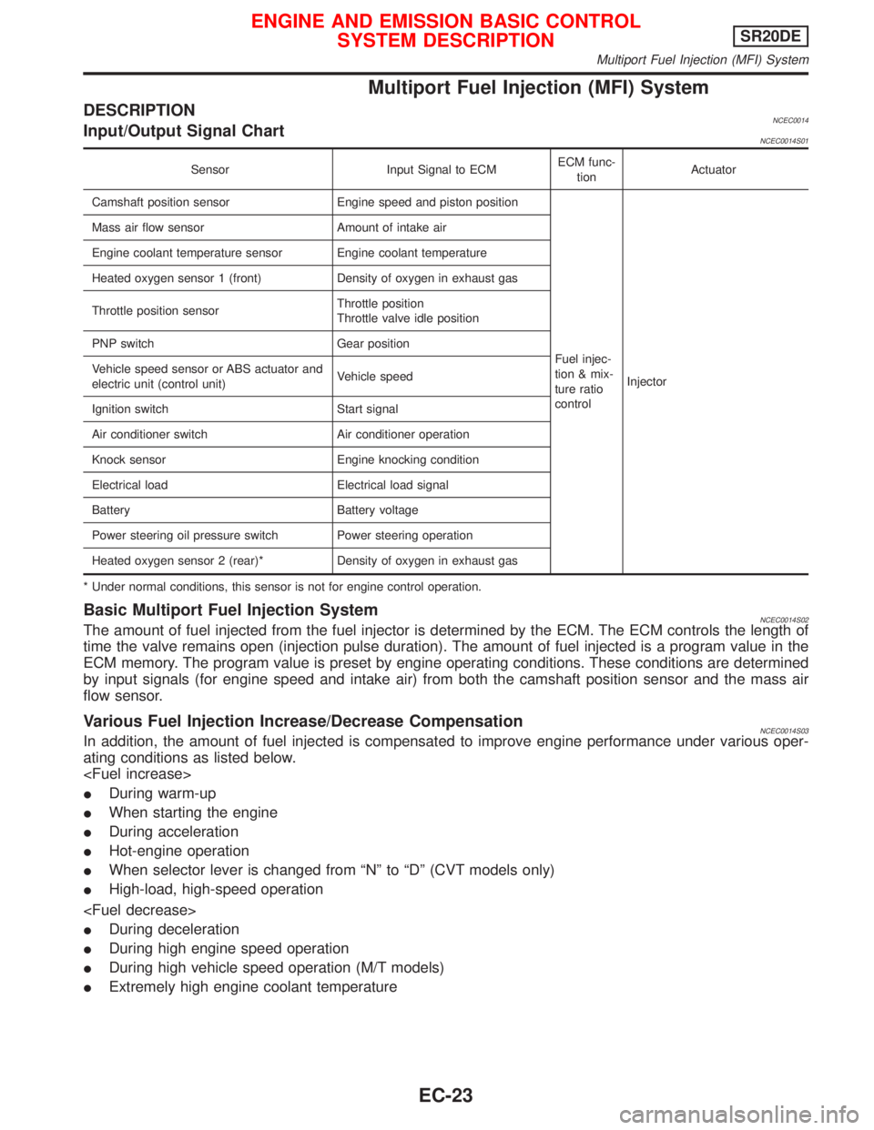
DESCRIPTIONNCEC0014Input/Output Signal ChartNCEC0014S01
Sensor Input Signal to ECMECM func-
tionActuator
Camshaft position sensor Engine speed and piston position
Fuel injec-
tion & mix-
ture ratio
controlInjector Mass air flow sensor Amount of intake air
Engine coolant temperature sensor Engine coolant temperature
Heated oxygen sensor 1 (front) Density of oxygen in exhaust gas
Throttle position sensorThrottle position
Throttle valve idle position
PNP switch Gear position
Vehicle speed sensor or ABS actuator and
electric unit (control unit)Vehicle speed
Ignition switch Start signal
Air conditioner switch Air conditioner operation
Knock sensor Engine knocking condition
Electrical load Electrical load signal
Battery Battery voltage
Power steering oil pressure switch Power steering operation
Heated oxygen sensor 2 (rear)* Density of oxygen in exhaust gas
* Under normal conditions, this sensor is not for engine control operation.
Basic Multiport Fuel Injection SystemNCEC0014S02The amount of fuel injected from the fuel injector is determined by the ECM. The ECM controls the length of
time the valve remains open (injection pulse duration). The amount of fuel injected is a program value in the
ECM memory. The program value is preset by engine operating conditions. These conditions are determined
by input signals (for engine speed and intake air) from both the camshaft position sensor and the mass air
flow sensor.
Various Fuel Injection Increase/Decrease CompensationNCEC0014S03In addition, the amount of fuel injected is compensated to improve engine performance under various oper-
ating conditions as listed below.
IDuring warm-up
IWhen starting the engine
IDuring acceleration
IHot-engine operation
IWhen selector lever is changed from ªNº to ªDº (CVT models only)
IHigh-load, high-speed operation
IDuring deceleration
IDuring high engine speed operation
IDuring high vehicle speed operation (M/T models)
IExtremely high engine coolant temperature
ENGINE AND EMISSION BASIC CONTROL
SYSTEM DESCRIPTIONSR20DE
Multiport Fuel Injection (MFI) System
EC-23
Page 826 of 2267
System DescriptionNCEC0015S02
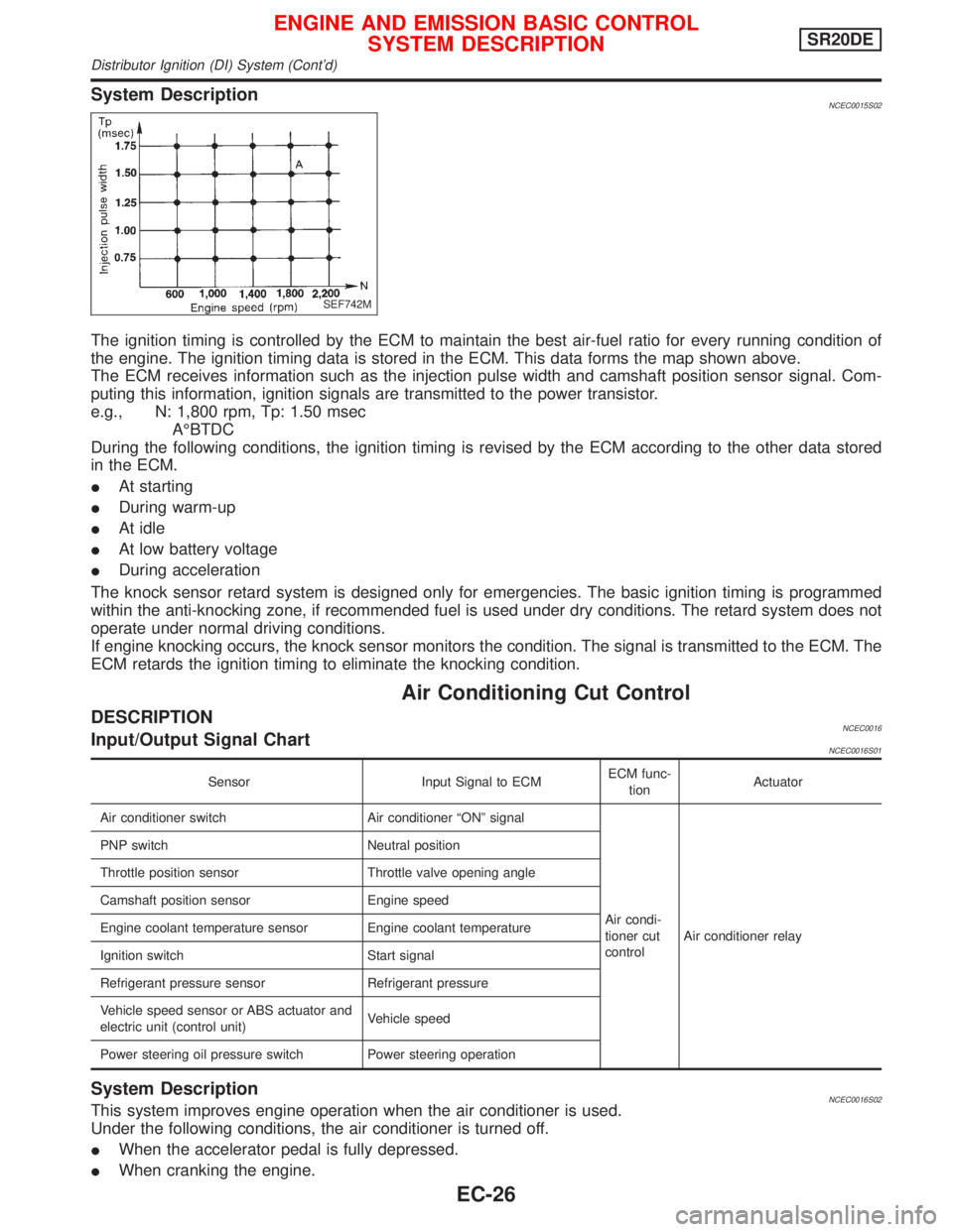
The ignition timing is controlled by the ECM to maintain the best air-fuel ratio for every running condition of
the engine. The ignition timing data is stored in the ECM. This data forms the map shown above.
The ECM receives information such as the injection pulse width and camshaft position sensor signal. Com-
puting this information, ignition signals are transmitted to the power transistor.
e.g., N: 1,800 rpm, Tp: 1.50 msec
AÉBTDC
During the following conditions, the ignition timing is revised by the ECM according to the other data stored
in the ECM.
IAt starting
IDuring warm-up
IAt idle
IAt low battery voltage
IDuring acceleration
The knock sensor retard system is designed only for emergencies. The basic ignition timing is programmed
within the anti-knocking zone, if recommended fuel is used under dry conditions. The retard system does not
operate under normal driving conditions.
If engine knocking occurs, the knock sensor monitors the condition. The signal is transmitted to the ECM. The
ECM retards the ignition timing to eliminate the knocking condition.
Air Conditioning Cut Control
DESCRIPTIONNCEC0016Input/Output Signal ChartNCEC0016S01
Sensor Input Signal to ECMECM func-
tionActuator
Air conditioner switch Air conditioner ªONº signal
Air condi-
tioner cut
controlAir conditioner relay PNP switch Neutral position
Throttle position sensor Throttle valve opening angle
Camshaft position sensor Engine speed
Engine coolant temperature sensor Engine coolant temperature
Ignition switch Start signal
Refrigerant pressure sensor Refrigerant pressure
Vehicle speed sensor or ABS actuator and
electric unit (control unit)Vehicle speed
Power steering oil pressure switch Power steering operation
System DescriptionNCEC0016S02This system improves engine operation when the air conditioner is used.
Under the following conditions, the air conditioner is turned off.
IWhen the accelerator pedal is fully depressed.
IWhen cranking the engine.
SEF742M
ENGINE AND EMISSION BASIC CONTROL
SYSTEM DESCRIPTIONSR20DE
Distributor Ignition (DI) System (Cont'd)
EC-26
Page 832 of 2267
If results are unsatisfactory, perform Fuel Pressure Regulator
Check, EC-SR-32.
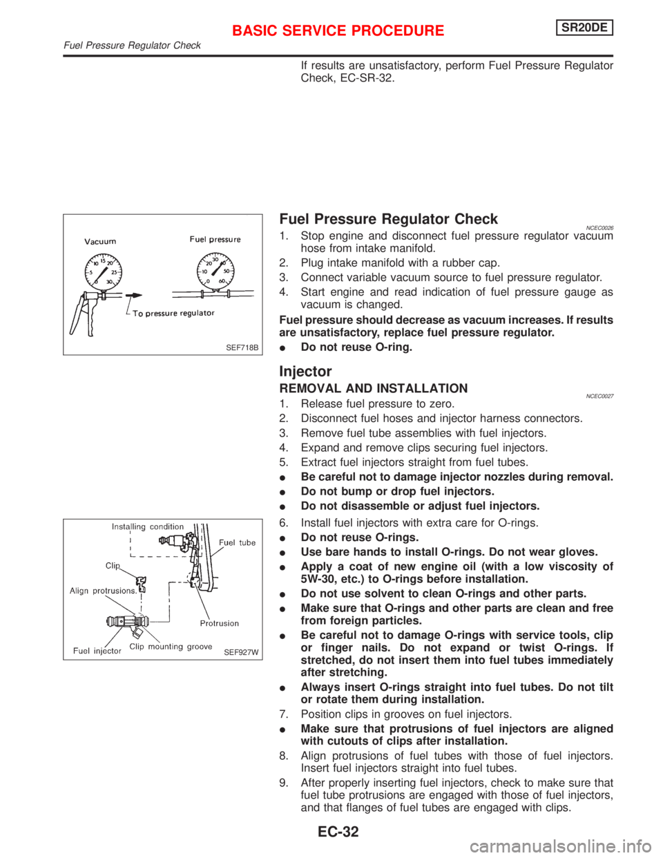
Fuel Pressure Regulator CheckNCEC00261. Stop engine and disconnect fuel pressure regulator vacuum
hose from intake manifold.
2. Plug intake manifold with a rubber cap.
3. Connect variable vacuum source to fuel pressure regulator.
4. Start engine and read indication of fuel pressure gauge as
vacuum is changed.
Fuel pressure should decrease as vacuum increases. If results
are unsatisfactory, replace fuel pressure regulator.
IDo not reuse O-ring.
Injector
REMOVAL AND INSTALLATIONNCEC00271. Release fuel pressure to zero.
2. Disconnect fuel hoses and injector harness connectors.
3. Remove fuel tube assemblies with fuel injectors.
4. Expand and remove clips securing fuel injectors.
5. Extract fuel injectors straight from fuel tubes.
IBe careful not to damage injector nozzles during removal.
IDo not bump or drop fuel injectors.
IDo not disassemble or adjust fuel injectors.
6. Install fuel injectors with extra care for O-rings.
IDo not reuse O-rings.
IUse bare hands to install O-rings. Do not wear gloves.
IApply a coat of new engine oil (with a low viscosity of
5W-30, etc.) to O-rings before installation.
IDo not use solvent to clean O-rings and other parts.
IMake sure that O-rings and other parts are clean and free
from foreign particles.
IBe careful not to damage O-rings with service tools, clip
or finger nails. Do not expand or twist O-rings. If
stretched, do not insert them into fuel tubes immediately
after stretching.
IAlways insert O-rings straight into fuel tubes. Do not tilt
or rotate them during installation.
7. Position clips in grooves on fuel injectors.
IMake sure that protrusions of fuel injectors are aligned
with cutouts of clips after installation.
8. Align protrusions of fuel tubes with those of fuel injectors.
Insert fuel injectors straight into fuel tubes.
9. After properly inserting fuel injectors, check to make sure that
fuel tube protrusions are engaged with those of fuel injectors,
and that flanges of fuel tubes are engaged with clips.
SEF718B
SEF927W
BASIC SERVICE PROCEDURESR20DE
Fuel Pressure Regulator Check
EC-32
Page 834 of 2267
Idle Speed/Ignition Timing/Idle Mixture Ratio
Adjustment
NCEC0028PREPARATIONNCEC0028S01IMake sure that the following parts are in good order.
a)Battery
b)Ignition system
c)Engine oil and coolant levels
d)Fuses
e)ECM harness connector
f)Vacuum hoses
g)Air intake system
(Oil filler cap, oil level gauge, etc.)
h)Fuel pressure
i)Engine compression
j)Throttle valve
k)EVAP system
IOn models equipped with air conditioner, checks should
be carried out while the air conditioner is ªOFFº.
IWhen checking idle speed on models equipped with CVT,
ignition timing and mixture ratio, checks should be carried
out while shift lever is in ªPº or ªNº position.
IWhen measuring ªCOº percentage, insert probe more
than 40 cm (15.7 in) into tail pipe.
ITurn off headlamps, heater blower, rear window defogger.
IOn vehicles equipped with daytime running light systems,
set lighting switch to the 1st position to light only small
lamps.
IKeep front wheels pointed straight ahead.
IIf engine stops immediately after starting or idle condition
is unstable, perform the following to initialize IACV-AAC
valve:
a)Stop engine and wait 9 seconds.
b)Turn ignition ªONº and wait 1 second.
c)Turn ignition ªOFFº and wait 9 seconds.
IMake the check after the cooling fan has stopped.
BASIC SERVICE PROCEDURESR20DE
Idle Speed/Ignition Timing/Idle Mixture Ratio Adjustment
EC-34
Page 869 of 2267
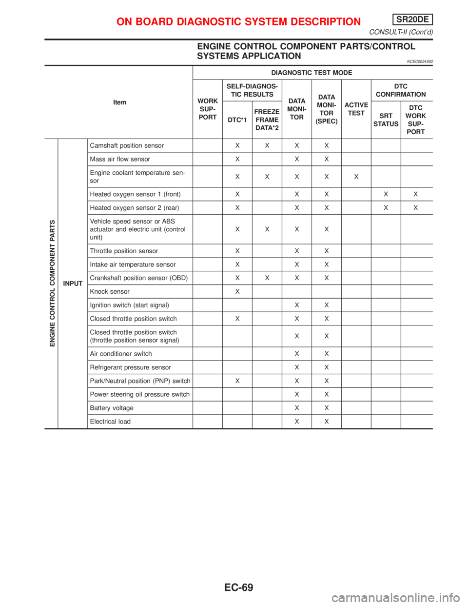
ENGINE CONTROL COMPONENT PARTS/CONTROL
SYSTEMS APPLICATION
NCEC0034S02
ItemDIAGNOSTIC TEST MODE
WORK
SUP-
PORTSELF-DIAGNOS-
TIC RESULTS
D ATA
MONI-
TORD ATA
MONI-
TOR
(SPEC)ACTIVE
TESTDTC
CONFIRMATION
DTC*1FREEZE
FRAME
DATA*2SRT
STATUSDTC
WORK
SUP-
PORT
ENGINE CONTROL COMPONENT PARTS
INPUTCamshaft position sensorXXXX
Mass air flow sensor X X X
Engine coolant temperature sen-
sorXXXXX
Heated oxygen sensor 1 (front) X X X X X
Heated oxygen sensor 2 (rear) X X X X X
Vehicle speed sensor or ABS
actuator and electric unit (control
unit)XXXX
Throttle position sensor X X X
Intake air temperature sensor X X X
Crankshaft position sensor (OBD)XXXX
Knock sensor X
Ignition switch (start signal) X X
Closed throttle position switch X X X
Closed throttle position switch
(throttle position sensor signal)XX
Air conditioner switch X X
Refrigerant pressure sensor X X
Park/Neutral position (PNP) switch X X X
Power steering oil pressure switch X X
Battery voltage X X
Electrical load X X
ON BOARD DIAGNOSTIC SYSTEM DESCRIPTIONSR20DE
CONSULT-II (Cont'd)
EC-69
Page 873 of 2267
![NISSAN PRIMERA 1999 Electronic Owners Manual Monitored item [Unit]ECM
input
signalsMain
signalsDescription Remarks
AIR COND SIG
[ON/OFF]qqIIndicates [ON/OFF] condition of the air
conditioner switch as determined by the
air conditioning signal.
P NISSAN PRIMERA 1999 Electronic Owners Manual Monitored item [Unit]ECM
input
signalsMain
signalsDescription Remarks
AIR COND SIG
[ON/OFF]qqIIndicates [ON/OFF] condition of the air
conditioner switch as determined by the
air conditioning signal.
P](/img/5/57377/w960_57377-872.png)
Monitored item [Unit]ECM
input
signalsMain
signalsDescription Remarks
AIR COND SIG
[ON/OFF]qqIIndicates [ON/OFF] condition of the air
conditioner switch as determined by the
air conditioning signal.
P/N POSI SW
[ON/OFF]qqIIndicates [ON/OFF] condition from the
PNP switch signal.
PW/ST SIGNAL
[ON/OFF]qqIIndicates [ON/OFF] condition of the
power steering oil pressure switch deter-
mined by the power steering oil pressure
switch signal.
LOAD SIGNAL
[ON/OFF]qqIIndicates [ON/OFF] condition from the
electrical load signal and/or lighting
switch.
ON ... rear defogger is operating and/or
lighting switch is on.
OFF ... rear defogger is not operating
and lighting switch is not on.
IGNITION SW
[ON/OFF]qIIndicates [ON/OFF] condition from igni-
tion switch.
HEATER FAN SW
[ON/OFF]qIIndicates [ON/OFF] condition from the
heater fan switch.
INJ PULSE -B1
[msec]qIIndicates the actual fuel injection pulse
width compensated by ECM according to
the input signals.IWhen the engine is stopped, a cer-
tain computed value is indicated.
B/FUEL SCHDL
[msec]IªBase fuel scheduleº indicates the fuel
injection pulse width programmed into
ECM, prior to any learned on board cor-
rection.
IGN TIMING [BTDC]qIIndicates the ignition timing computed by
ECM according to the input signals.
IACV-AAC/V [step]qIIndicates the IACV-AAC valve control
value computed by ECM according to
the input signals.
A/F ALPHA -B1 [%]qIIndicates the mean value of the air-fuel
ratio feedback correction factor per
cycle.IWhen the engine is stopped, a cer-
tain value is indicated.
IThis data also includes the data for
the air-fuel ratio learning control.
AIR COND RLY
[ON/OFF]qIIndicates the air conditioner relay control
condition determined by ECM according
to the input signals.
FUEL PUMP RLY
[ON/OFF]qIIndicates the fuel pump relay control
condition determined by ECM according
to the input signals.
COOLING FAN
[HI/LOW/OFF]qIIndicates the control condition of the
cooling fan determined by ECM accord-
ing to the input signals.
HI ... High speed operation
LOW ... Low speed operation
OFF ... Stop
HO2S1 HTR (B1)
[ON/OFF]IIndicates [ON/OFF] condition of heated
oxygen sensor 1 (front) heater deter-
mined by ECM according to the input
signals.
ON BOARD DIAGNOSTIC SYSTEM DESCRIPTIONSR20DE
CONSULT-II (Cont'd)
EC-73
Page 894 of 2267
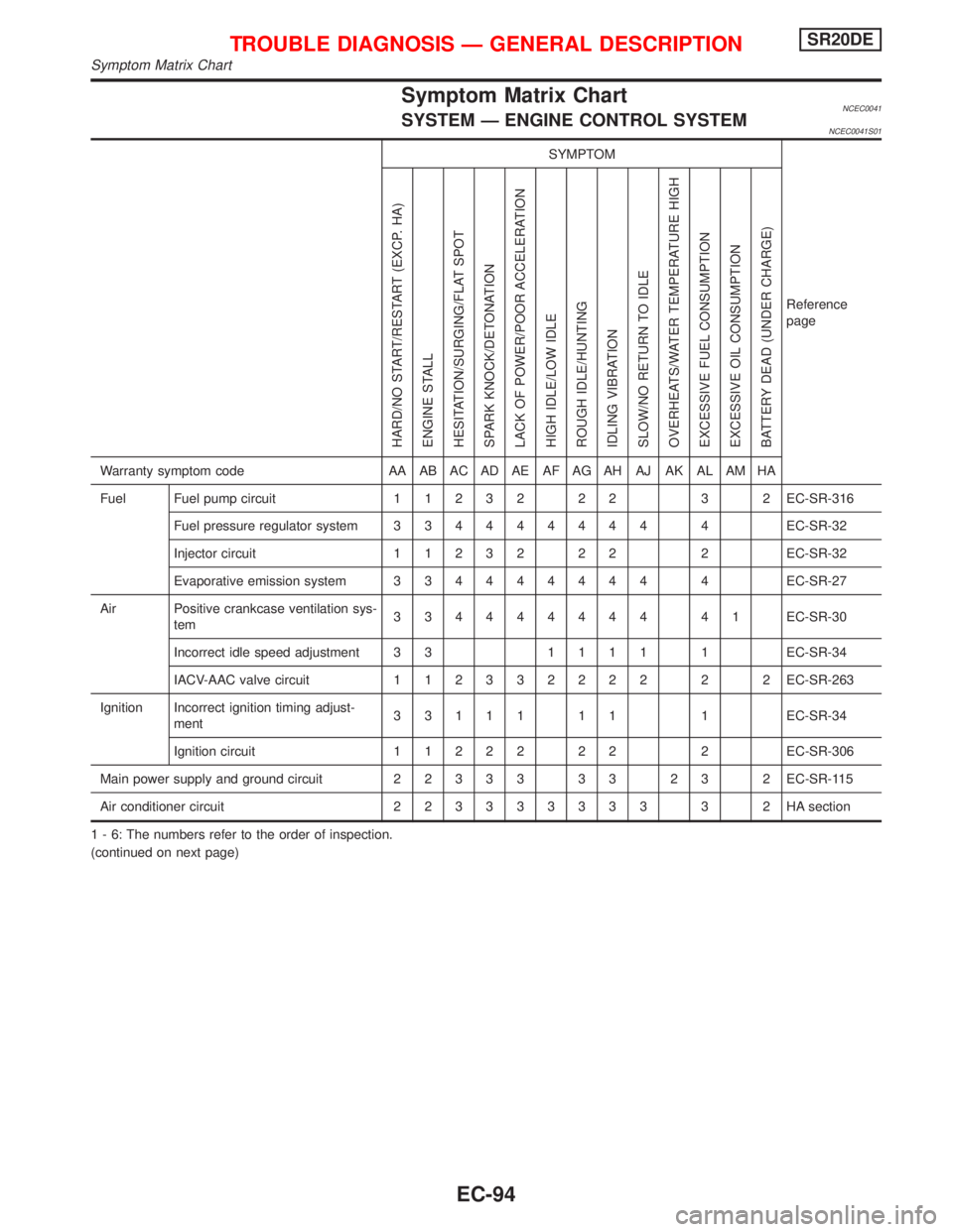
Symptom Matrix ChartNCEC0041SYSTEM Ð ENGINE CONTROL SYSTEMNCEC0041S01
SYMPTOM
Reference
page
HARD/NO START/RESTART (EXCP. HA)
ENGINE STALL
HESITATION/SURGING/FLAT SPOT
SPARK KNOCK/DETONATION
LACK OF POWER/POOR ACCELERATION
HIGH IDLE/LOW IDLE
ROUGH IDLE/HUNTING
IDLING VIBRATION
SLOW/NO RETURN TO IDLE
OVERHEATS/WATER TEMPERATURE HIGH
EXCESSIVE FUEL CONSUMPTION
EXCESSIVE OIL CONSUMPTION
BATTERY DEAD (UNDER CHARGE)
Warranty symptom code AA AB AC AD AE AF AG AH AJ AK AL AM HA
Fuel Fuel pump circuit11232 22 3 2EC-SR-316
Fuel pressure regulator system334444444 4EC-SR-32
Injector circuit11232 22 2EC-SR-32
Evaporative emission system334444444 4EC-SR-27
Air Positive crankcase ventilation sys-
tem334444444 41EC-SR-30
Incorrect idle speed adjustment 3 31111 1EC-SR-34
IACV-AAC valve circuit112332222 2 2EC-SR-263
Ignition Incorrect ignition timing adjust-
ment33111 11 1EC-SR-34
Ignition circuit11222 22 2EC-SR-306
Main power supply and ground circuit22333 33 23 2EC-SR-115
Air conditioner circuit223333333 3 2HAsection
1 - 6: The numbers refer to the order of inspection.
(continued on next page)
TROUBLE DIAGNOSIS Ð GENERAL DESCRIPTIONSR20DE
Symptom Matrix Chart
EC-94
Page 895 of 2267
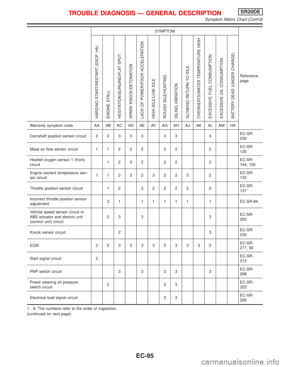
SYMPTOM
Reference
page
HARD/NO START/RESTART (EXCP. HA)
ENGINE STALL
HESITATION/SURGING/FLAT SPOT
SPARK KNOCK/DETONATION
LACK OF POWER/POOR ACCELERATION
HIGH IDLE/LOW IDLE
ROUGH IDLE/HUNTING
IDLING VIBRATION
SLOW/NO RETURN TO IDLE
OVERHEATS/WATER TEMPERATURE HIGH
EXCESSIVE FUEL CONSUMPTION
EXCESSIVE OIL CONSUMPTION
BATTERY DEAD (UNDER CHARGE)
Warranty symptom code AA AB AC AD AE AF AG AH AJ AK AL AM HA
Camshaft position sensor circuit22333 33 3EC-SR-
239
Mass air flow sensor circuit11222 22 2EC-SR-
120
Heated oxygen sensor 1 (front)
circuit1232 22 2EC-SR-
144, 150
Engine coolant temperature sen-
sor circuit112323223 2EC-SR-
132
Throttle position sensor circuit 1 222222 2EC-SR-
137
Incorrect throttle position sensor
adjustment31 11111 1EC-SR-84
Vehicle speed sensor circuit or
ABS actuator and electric unit
(control unit) circuit23 3 3EC-SR-
255
Knock sensor circuit 2 3EC-SR-
230
ECM 22333333333EC-SR-
277, 93
Start signal circuit 2EC-SR-
312
PNP switch circuit 3 3 3 3 3EC-SR-
298
Power steering oil pressure
switch circuit233EC-SR-
322
Electrical load signal circuit 3 3EC-SR-
326
1 - 6: The numbers refer to the order of inspection.
(continued on next page)
TROUBLE DIAGNOSIS Ð GENERAL DESCRIPTIONSR20DE
Symptom Matrix Chart (Cont'd)
EC-95
Page 1063 of 2267
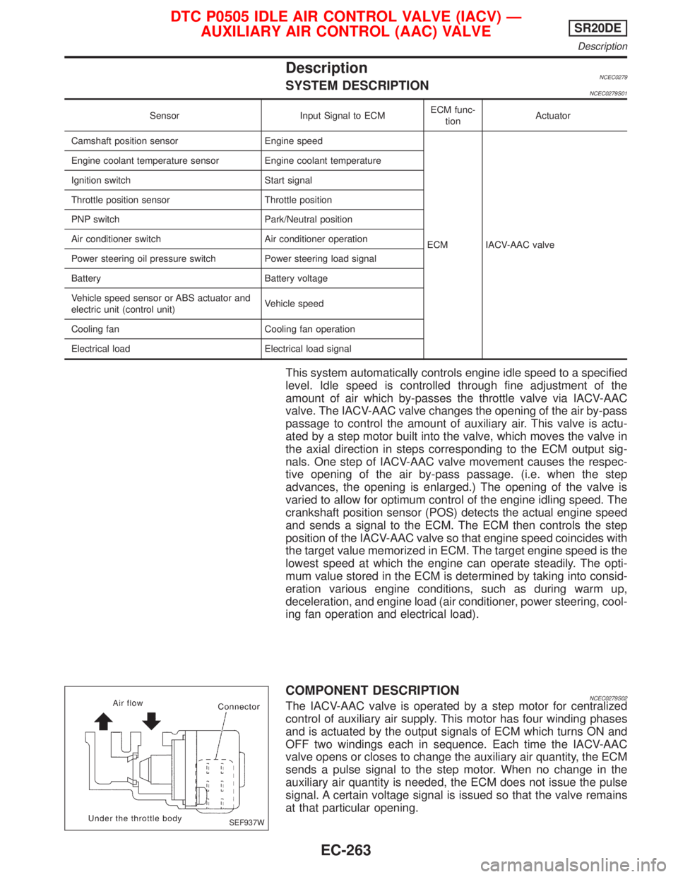
DescriptionNCEC0279SYSTEM DESCRIPTIONNCEC0279S01
Sensor Input Signal to ECMECM func-
tionActuator
Camshaft position sensor Engine speed
ECM IACV-AAC valve Engine coolant temperature sensor Engine coolant temperature
Ignition switch Start signal
Throttle position sensor Throttle position
PNP switch Park/Neutral position
Air conditioner switch Air conditioner operation
Power steering oil pressure switch Power steering load signal
Battery Battery voltage
Vehicle speed sensor or ABS actuator and
electric unit (control unit)Vehicle speed
Cooling fan Cooling fan operation
Electrical load Electrical load signal
This system automatically controls engine idle speed to a specified
level. Idle speed is controlled through fine adjustment of the
amount of air which by-passes the throttle valve via IACV-AAC
valve. The IACV-AAC valve changes the opening of the air by-pass
passage to control the amount of auxiliary air. This valve is actu-
ated by a step motor built into the valve, which moves the valve in
the axial direction in steps corresponding to the ECM output sig-
nals. One step of IACV-AAC valve movement causes the respec-
tive opening of the air by-pass passage. (i.e. when the step
advances, the opening is enlarged.) The opening of the valve is
varied to allow for optimum control of the engine idling speed. The
crankshaft position sensor (POS) detects the actual engine speed
and sends a signal to the ECM. The ECM then controls the step
position of the IACV-AAC valve so that engine speed coincides with
the target value memorized in ECM. The target engine speed is the
lowest speed at which the engine can operate steadily. The opti-
mum value stored in the ECM is determined by taking into consid-
eration various engine conditions, such as during warm up,
deceleration, and engine load (air conditioner, power steering, cool-
ing fan operation and electrical load).
COMPONENT DESCRIPTIONNCEC0279S02The IACV-AAC valve is operated by a step motor for centralized
control of auxiliary air supply. This motor has four winding phases
and is actuated by the output signals of ECM which turns ON and
OFF two windings each in sequence. Each time the IACV-AAC
valve opens or closes to change the auxiliary air quantity, the ECM
sends a pulse signal to the step motor. When no change in the
auxiliary air quantity is needed, the ECM does not issue the pulse
signal. A certain voltage signal is issued so that the valve remains
at that particular opening.
SEF937W
DTC P0505 IDLE AIR CONTROL VALVE (IACV) Ð
AUXILIARY AIR CONTROL (AAC) VALVESR20DE
Description
EC-263
Page 1080 of 2267
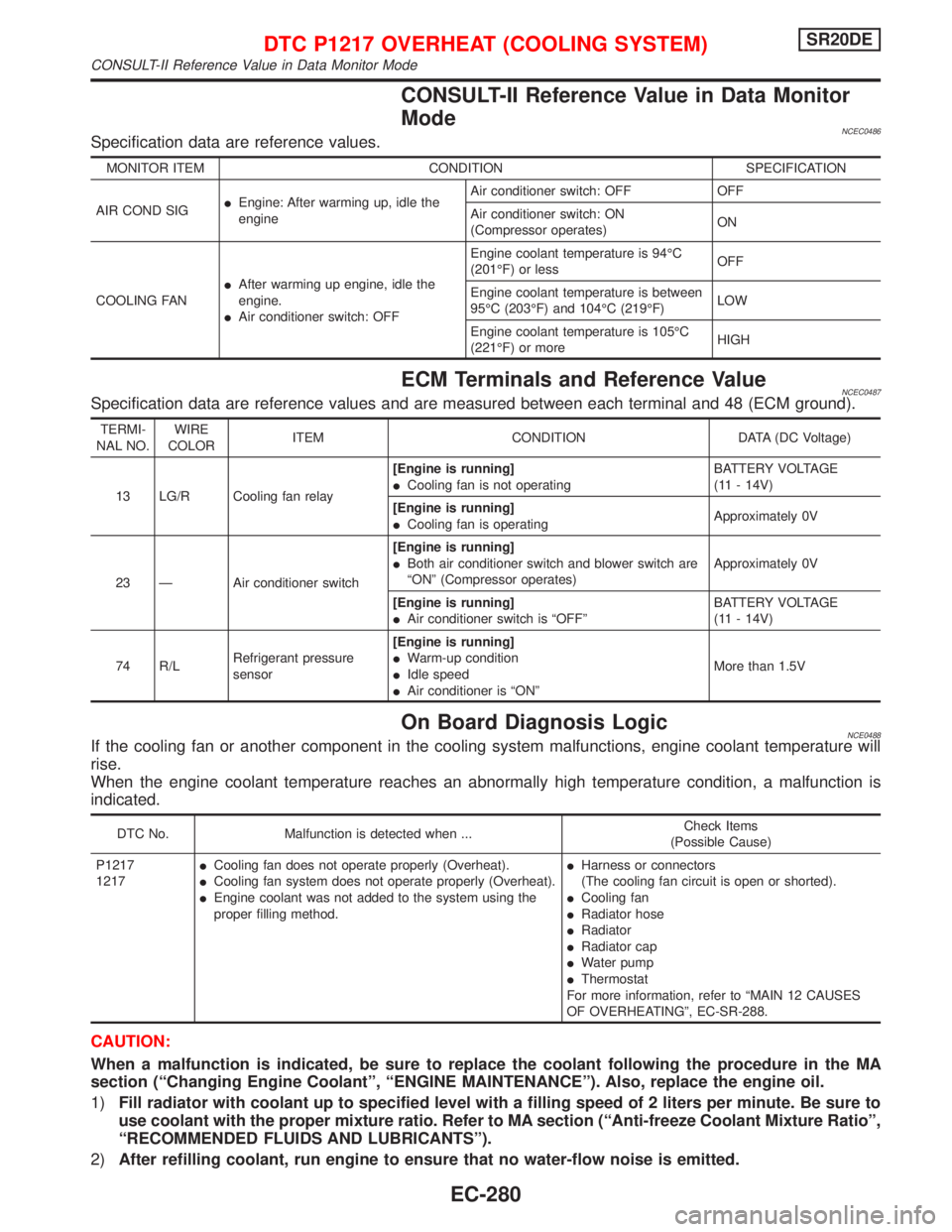
CONSULT-II Reference Value in Data Monitor
Mode
NCEC0486Specification data are reference values.
MONITOR ITEM CONDITION SPECIFICATION
AIR COND SIGIEngine: After warming up, idle the
engineAir conditioner switch: OFF OFF
Air conditioner switch: ON
(Compressor operates)ON
COOLING FANIAfter warming up engine, idle the
engine.
IAir conditioner switch: OFFEngine coolant temperature is 94ÉC
(201ÉF) or lessOFF
Engine coolant temperature is between
95ÉC (203ÉF) and 104ÉC (219ÉF)LOW
Engine coolant temperature is 105ÉC
(221ÉF) or moreHIGH
ECM Terminals and Reference ValueNCEC0487Specification data are reference values and are measured between each terminal and 48 (ECM ground).
TERMI-
NAL NO.WIRE
COLORITEM CONDITION DATA (DC Voltage)
13 LG/R Cooling fan relay[Engine is running]
ICooling fan is not operatingBATTERY VOLTAGE
(11 - 14V)
[Engine is running]
ICooling fan is operatingApproximately 0V
23 Ð Air conditioner switch[Engine is running]
IBoth air conditioner switch and blower switch are
ªONº (Compressor operates)Approximately 0V
[Engine is running]
IAir conditioner switch is ªOFFºBATTERY VOLTAGE
(11 - 14V)
74 R/LRefrigerant pressure
sensor[Engine is running]
IWarm-up condition
IIdle speed
IAir conditioner is ªONºMore than 1.5V
On Board Diagnosis LogicNCE0488If the cooling fan or another component in the cooling system malfunctions, engine coolant temperature will
rise.
When the engine coolant temperature reaches an abnormally high temperature condition, a malfunction is
indicated.
DTC No. Malfunction is detected when ...Check Items
(Possible Cause)
P1217
1217ICooling fan does not operate properly (Overheat).
ICooling fan system does not operate properly (Overheat).
IEngine coolant was not added to the system using the
proper filling method.IHarness or connectors
(The cooling fan circuit is open or shorted).
ICooling fan
IRadiator hose
IRadiator
IRadiator cap
IWater pump
IThermostat
For more information, refer to ªMAIN 12 CAUSES
OF OVERHEATINGº, EC-SR-288.
CAUTION:
When a malfunction is indicated, be sure to replace the coolant following the procedure in the MA
section (ªChanging Engine Coolantº, ªENGINE MAINTENANCEº). Also, replace the engine oil.
1)Fill radiator with coolant up to specified level with a filling speed of 2 liters per minute. Be sure to
use coolant with the proper mixture ratio. Refer to MA section (ªAnti-freeze Coolant Mixture Ratioº,
ªRECOMMENDED FLUIDS AND LUBRICANTSº).
2)After refilling coolant, run engine to ensure that no water-flow noise is emitted.
DTC P1217 OVERHEAT (COOLING SYSTEM)SR20DE
CONSULT-II Reference Value in Data Monitor Mode
EC-280