low oil pressure NISSAN PRIMERA 1999 Electronic User Guide
[x] Cancel search | Manufacturer: NISSAN, Model Year: 1999, Model line: PRIMERA, Model: NISSAN PRIMERA 1999Pages: 2267, PDF Size: 35.74 MB
Page 498 of 2267
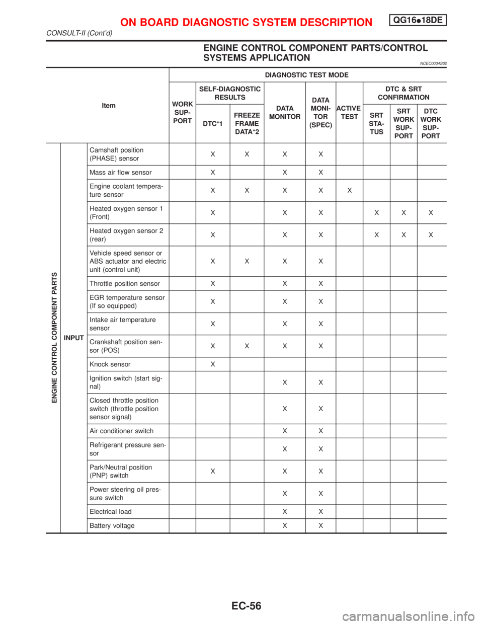
ENGINE CONTROL COMPONENT PARTS/CONTROL
SYSTEMS APPLICATION
NCEC0034S02
ItemDIAGNOSTIC TEST MODE
WORK
SUP-
PORTSELF-DIAGNOSTIC
RESULTS
D ATA
MONITORD ATA
MONI-
TOR
(SPEC)ACTIVE
TESTDTC & SRT
CONFIRMATION
DTC*1FREEZE
FRAME
DATA*2SRT
STA-
TUSSRT
WORK
SUP-
PORTDTC
WORK
SUP-
PORT
ENGINE CONTROL COMPONENT PARTS
INPUTCamshaft position
(PHASE) sensorXX X X
Mass air flow sensor X X X
Engine coolant tempera-
ture sensorXX X XX
Heated oxygen sensor 1
(Front)X X X XXX
Heated oxygen sensor 2
(rear)X X X XXX
Vehicle speed sensor or
ABS actuator and electric
unit (control unit)XX X X
Throttle position sensor X X X
EGR temperature sensor
(If so equipped)XXX
Intake air temperature
sensorXXX
Crankshaft position sen-
sor (POS)XX X X
Knock sensor X
Ignition switch (start sig-
nal)XX
Closed throttle position
switch (throttle position
sensor signal)XX
Air conditioner switch X X
Refrigerant pressure sen-
sorXX
Park/Neutral position
(PNP) switchXXX
Power steering oil pres-
sure switchXX
Electrical load X X
Battery voltage X X
ON BOARD DIAGNOSTIC SYSTEM DESCRIPTIONQG16I18DE
CONSULT-II (Cont'd)
EC-56
Page 502 of 2267
![NISSAN PRIMERA 1999 Electronic User Guide Monitored item [Unit]ECM
input
signalsMain
signalsDescription Remarks
AIR COND SIG
[ON/OFF]qqIIndicates [ON/OFF] condition of the air condi-
tioner switch as determined by the air condition-
ing signa NISSAN PRIMERA 1999 Electronic User Guide Monitored item [Unit]ECM
input
signalsMain
signalsDescription Remarks
AIR COND SIG
[ON/OFF]qqIIndicates [ON/OFF] condition of the air condi-
tioner switch as determined by the air condition-
ing signa](/img/5/57377/w960_57377-501.png)
Monitored item [Unit]ECM
input
signalsMain
signalsDescription Remarks
AIR COND SIG
[ON/OFF]qqIIndicates [ON/OFF] condition of the air condi-
tioner switch as determined by the air condition-
ing signal.
P/N POSI SW
[ON/OFF]qqIIndicates [ON/OFF] condition from the PNP
switch signal.
PW/ST SIGNAL
[ON/OFF]qqIIndicates [ON/OFF] condition of the power steer-
ing oil pressure switch determined by the power
steering oil pressure switch signal.
LOAD SIGNAL
[ON/OFF]qqIIndicates [ON/OFF] condition from the electrical
load signal and/or lighting switch.
ON ... rear defogger is operating and/or lighting
switch is on.
OFF ... rear defogger is not operating and light-
ing switch is not on.
IGNITION SW
[ON/OFF]qIIndicates [ON/OFF] condition from ignition
switch.
HEATER FAN SW
[ON/OFF]qIIndicates [ON/OFF] condition from the heater
fan switch.
INJ PULSE-B1
[msec]qIIndicates the actual fuel injection pulse width
compensated by ECM according to the input
signals.IWhen the engine is stopped, a
certain computed value is indi-
cated.
B/FUEL SCHDL
[msec]IªBase fuel scheduleº indicates the fuel injection
pulse width programmed into ECM, prior to any
learned on board correction.
IGN TIMING [BTDC]qIIndicates the ignition timing computed by ECM
according to the input signals.
IACV-AAC/V [step]qIIndicates the IACV-AAC valve control value
computed by ECM according to the input sig-
nals.
A/F ALPHA-B1 [%]qIIndicates the mean value of the air-fuel ratio
feedback correction factor per cycle.IWhen the engine is stopped, a
certain value is indicated.
IThis data also includes the data
for the air-fuel ratio learning
control.
AIR COND RLY
[ON/OFF]qIIndicates the air conditioner relay control condi-
tion determined by ECM according to the input
signals.
FUEL PUMP RLY
[ON/OFF]qIIndicates the fuel pump relay control condition
determined by ECM according to the input sig-
nals.
INT/V SOL-B1
[ON/OFF]IThe control condition of the valve timing sole-
noid valve (determined by ECM according to the
input signal) is indicated.
ON ... Intake valve timing control operating
OFF ... Intake valve timing control not operating
COOLING FAN
[ON/OFF]qIIndicates the control condition of the cooling fan
determined by ECM according to the input sig-
nals.
HI ... High speed operation
LOW ... Low speed operation
OFF ... Stop
ON BOARD DIAGNOSTIC SYSTEM DESCRIPTIONQG16I18DE
CONSULT-II (Cont'd)
EC-60
Page 524 of 2267
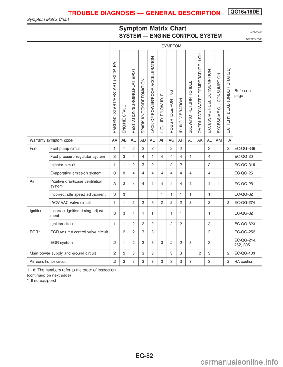
Symptom Matrix ChartNCEC0041SYSTEM Ð ENGINE CONTROL SYSTEMNCEC0041S01
SYMPTOM
Reference
page
HARD/NO START/RESTART (EXCP. HA)
ENGINE STALL
HESITATION/SURGING/FLAT SPOT
SPARK KNOCK/DETONATION
LACK OF POWER/POOR ACCELERATION
HIGH IDLE/LOW IDLE
ROUGH IDLE/HUNTING
IDLING VIBRATION
SLOW/NO RETURN TO IDLE
OVERHEATS/WATER TEMPERATURE HIGH
EXCESSIVE FUEL CONSUMPTION
EXCESSIVE OIL CONSUMPTION
BATTERY DEAD (UNDER CHARGE)
Warranty symptom code AA AB AC AD AE AF AG AH AJ AK AL AM HA
Fuel Fuel pump circuit11232 22 3 2EC-QG-336
Fuel pressure regulator system334444444 4EC-QG-30
Injector circuit11232 22 2EC-QG-319
Evaporative emission system334444444 4EC-QG-25
Air Positive crankcase ventilation
system334444444 41EC-QG-28
Incorrect idle speed adjustment 3 31111 1EC-QG-32
IACV-AAC valve circuit112332222 2 2EC-QG-274
Ignition Incorrect ignition timing adjust-
ment33111 11 1EC-QG-32
Ignition circuit11222 22 2EC-QG-323
EGR* EGR volume control valve circuit2233 3EC-QG-252
EGR system212333223 3EC-QG-244,
252, 305
Main power supply and ground circuit22333 33 23 2EC-QG-103
Air conditioner circuit223333333 3 2HAsection
1 - 6: The numbers refer to the order of inspection.
(continued on next page)
*: If so equipped
TROUBLE DIAGNOSIS Ð GENERAL DESCRIPTIONQG16I18DE
Symptom Matrix Chart
EC-82
Page 525 of 2267
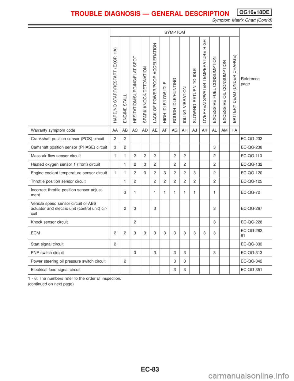
SYMPTOM
Reference
page
HARD/NO START/RESTART (EXCP. HA)
ENGINE STALL
HESITATION/SURGING/FLAT SPOT
SPARK KNOCK/DETONATION
LACK OF POWER/POOR ACCELERATION
HIGH IDLE/LOW IDLE
ROUGH IDLE/HUNTING
IDLING VIBRATION
SLOW/NO RETURN TO IDLE
OVERHEATS/WATER TEMPERATURE HIGH
EXCESSIVE FUEL CONSUMPTION
EXCESSIVE OIL CONSUMPTION
BATTERY DEAD (UNDER CHARGE)
Warranty symptom code AA AB AC AD AE AF AG AH AJ AK AL AM HA
Crankshaft position sensor (POS) circuit 2 2 EC-QG-232
Camshaft position sensor (PHASE) circuit 3 2 3 EC-QG-238
Mass air flow sensor circuit11222 22 2EC-QG-110
Heated oxygen sensor 1 (front) circuit1232 22 2EC-QG-132
Engine coolant temperature sensor circuit112323223 2EC-QG-120
Throttle position sensor circuit 1 222222 2EC-QG-125
Incorrect throttle position sensor adjust-
ment31 11111 1EC-QG-72
Vehicle speed sensor circuit or ABS
actuator and electric unit (control unit) cir-
cuit2 3 3 3 EC-QG-267
Knock sensor circuit 2 3 EC-QG-228
ECM 22333333333EC-QG-282,
81
Start signal circuit 2 EC-QG-332
PNP switch circuit 3 3 3 3 3 EC-QG-313
Power steering oil pressure switch circuit 2 3 3 EC-QG-342
Electrical load signal circuit 3 3 EC-QG-351
1 - 6: The numbers refer to the order of inspection.
(continued on next page)
TROUBLE DIAGNOSIS Ð GENERAL DESCRIPTIONQG16I18DE
Symptom Matrix Chart (Cont'd)
EC-83
Page 716 of 2267
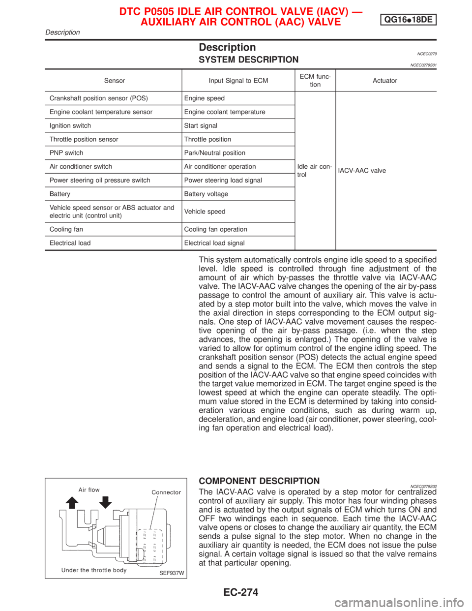
DescriptionNCEC0279SYSTEM DESCRIPTIONNCEC0279S01
Sensor Input Signal to ECMECM func-
tionActuator
Crankshaft position sensor (POS) Engine speed
Idle air con-
trolIACV-AAC valve Engine coolant temperature sensor Engine coolant temperature
Ignition switch Start signal
Throttle position sensor Throttle position
PNP switch Park/Neutral position
Air conditioner switch Air conditioner operation
Power steering oil pressure switch Power steering load signal
Battery Battery voltage
Vehicle speed sensor or ABS actuator and
electric unit (control unit)Vehicle speed
Cooling fan Cooling fan operation
Electrical load Electrical load signal
This system automatically controls engine idle speed to a specified
level. Idle speed is controlled through fine adjustment of the
amount of air which by-passes the throttle valve via IACV-AAC
valve. The IACV-AAC valve changes the opening of the air by-pass
passage to control the amount of auxiliary air. This valve is actu-
ated by a step motor built into the valve, which moves the valve in
the axial direction in steps corresponding to the ECM output sig-
nals. One step of IACV-AAC valve movement causes the respec-
tive opening of the air by-pass passage. (i.e. when the step
advances, the opening is enlarged.) The opening of the valve is
varied to allow for optimum control of the engine idling speed. The
crankshaft position sensor (POS) detects the actual engine speed
and sends a signal to the ECM. The ECM then controls the step
position of the IACV-AAC valve so that engine speed coincides with
the target value memorized in ECM. The target engine speed is the
lowest speed at which the engine can operate steadily. The opti-
mum value stored in the ECM is determined by taking into consid-
eration various engine conditions, such as during warm up,
deceleration, and engine load (air conditioner, power steering, cool-
ing fan operation and electrical load).
COMPONENT DESCRIPTIONNCEC0279S02The IACV-AAC valve is operated by a step motor for centralized
control of auxiliary air supply. This motor has four winding phases
and is actuated by the output signals of ECM which turns ON and
OFF two windings each in sequence. Each time the IACV-AAC
valve opens or closes to change the auxiliary air quantity, the ECM
sends a pulse signal to the step motor. When no change in the
auxiliary air quantity is needed, the ECM does not issue the pulse
signal. A certain voltage signal is issued so that the valve remains
at that particular opening.
SEF937W
DTC P0505 IDLE AIR CONTROL VALVE (IACV) Ð
AUXILIARY AIR CONTROL (AAC) VALVEQG16I18DE
Description
EC-274
Page 786 of 2267
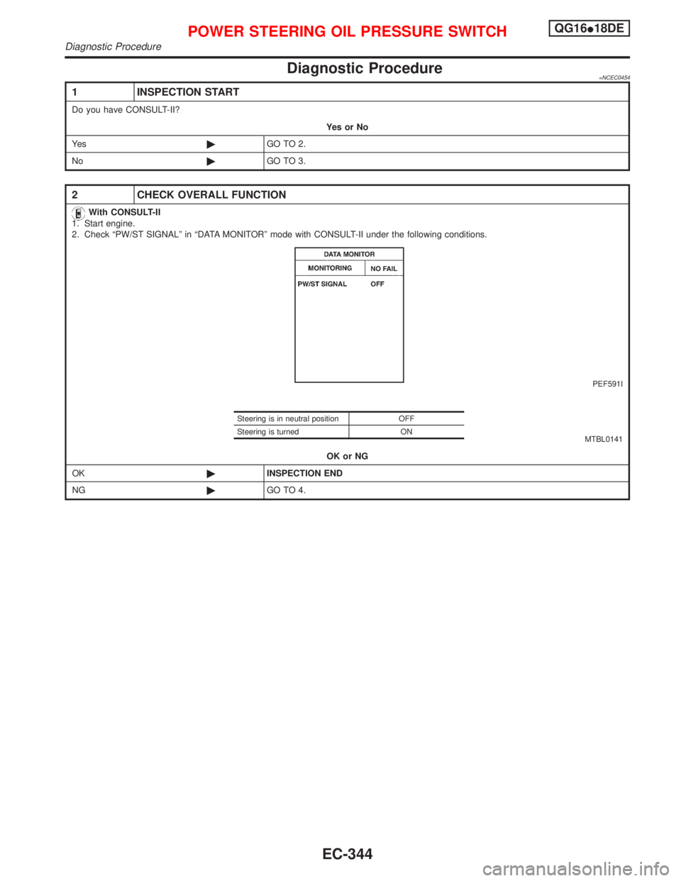
Diagnostic Procedure=NCEC0454
1 INSPECTION START
Do you have CONSULT-II?
YesorNo
Ye s©GO TO 2.
No©GO TO 3.
2 CHECK OVERALL FUNCTION
With CONSULT-II
1. Start engine.
2. Check ªPW/ST SIGNALº in ªDATA MONITORº mode with CONSULT-II under the following conditions.
PEF591I
MTBL0141
OK or NG
OK©INSPECTION END
NG©GO TO 4.
Steering is in neutral position OFF
Steering is turned ON
POWER STEERING OIL PRESSURE SWITCHQG16I18DE
Diagnostic Procedure
EC-344
Page 787 of 2267
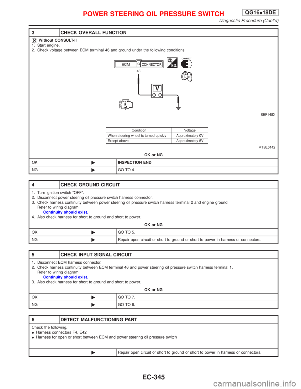
3 CHECK OVERALL FUNCTION
Without CONSULT-II
1. Start engine.
2. Check voltage between ECM terminal 46 and ground under the following conditions.
SEF148X
MTBL0142
OK or NG
OK©INSPECTION END
NG©GO TO 4.
4 CHECK GROUND CIRCUIT
1. Turn ignition switch ªOFFº.
2. Disconnect power steering oil pressure switch harness connector.
3. Check harness continuity between power steering oil pressure switch harness terminal 2 and engine ground.
Refer to wiring diagram.
Continuity should exist.
4. Also check harness for short to ground and short to power.
OK or NG
OK©GO TO 5.
NG©Repair open circuit or short to ground or short to power in harness or connectors.
5 CHECK INPUT SIGNAL CIRCUIT
1. Disconnect ECM harness connector.
2. Check harness continuity between ECM terminal 46 and power steering oil pressure switch harness terminal 1.
Refer to wiring diagram.
Continuity should exist.
3. Also check harness for short to ground and short to power.
OK or NG
OK©GO TO 7.
NG©GO TO 6.
6 DETECT MALFUNCTIONING PART
Check the following.
IHarness connectors F4, E42
IHarness for open or short between ECM and power steering oil pressure switch
©Repair open circuit or short to ground or short to power in harness or connectors.
Condition Voltage
When steering wheel is turned quickly Approximately 0V
Except above Approximately 5V
POWER STEERING OIL PRESSURE SWITCHQG16I18DE
Diagnostic Procedure (Cont'd)
EC-345
Page 805 of 2267
CONSULT-II Reference Value in Data Monitor
Mode ........................................................................306
ECM Terminals and Reference Value .....................306
Wiring Diagram ........................................................308
Diagnostic Procedure ..............................................309
Component Inspection .............................................310
START SIGNAL...........................................................312
CONSULT-II Reference Value in Data Monitor
Mode ........................................................................312
ECM Terminals and Reference Value .....................312
Wiring Diagram ........................................................313
Diagnostic Procedure ..............................................314
FUEL PUMP.................................................................316
System Description ..................................................316
Component Description ...........................................316
CONSULT-II Reference Value in Data Monitor
Mode ........................................................................316
ECM Terminals and Reference Value .....................316
Wiring Diagram ........................................................317
Diagnostic Procedure ..............................................318
Component Inspection .............................................320
POWER STEERING OIL PRESSURE SWITCH.........321
Component Description ...........................................321
CONSULT-II Reference Value in Data Monitor
Mode ........................................................................321
ECM Terminals and Reference Value .....................321
Wiring Diagram ........................................................322Diagnostic Procedure ..............................................323
Component Inspection .............................................324
ELECTRICAL LOAD SIGNAL.....................................325
CONSULT-II Reference Value in Data Monitor
Mode ........................................................................325
ECM Terminals and Reference Value .....................325
Wiring Diagram ........................................................326
MI & DATA LINK CONNECTORS..............................329
Wiring Diagram ........................................................329
SERVICE DATA AND SPECIFICATIONS (SDS).......330
Fuel Pressure Regulator..........................................330
Idle Speed and Ignition Timing ................................330
Ignition Coil ..............................................................330
Mass Air Flow Sensor..............................................330
Engine Coolant Temperature Sensor ......................330
Fuel Pump ...............................................................330
IACV-AAC Valve ......................................................330
Injector .....................................................................330
Throttle Position Sensor ..........................................331
Heated Oxygen Sensor 1 (Front) Heater ................331
Intake Air Temperature Sensor ................................331
EVAP Canister Purge Volume Control Valve ..........331
Heated Oxygen Sensor 1 (Rear) Heater.................331
Crankshaft Position Sensor (OBD)..........................331
CONTENTS(Cont'd)
EC-5
Page 815 of 2267
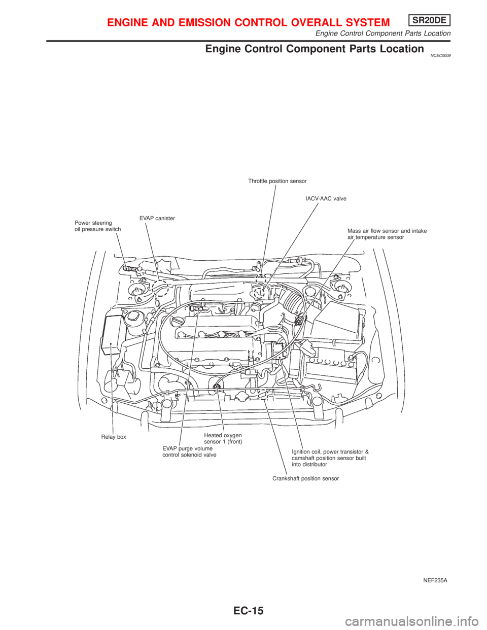
Engine Control Component Parts LocationNCEC0009
NEF235A Throttle position sensor
IACV-AAC valve
Mass air flow sensor and intake
air temperature sensor
Ignition coil, power transistor &
camshaft position sensor built
into distributor
Crankshaft position sensor Relay box
EVAP purge volume
control solenoid valveHeated oxygen
sensor 1 (front) EVAP canister
Power steering
oil pressure switch
ENGINE AND EMISSION CONTROL OVERALL SYSTEMSR20DE
Engine Control Component Parts Location
EC-15
Page 822 of 2267
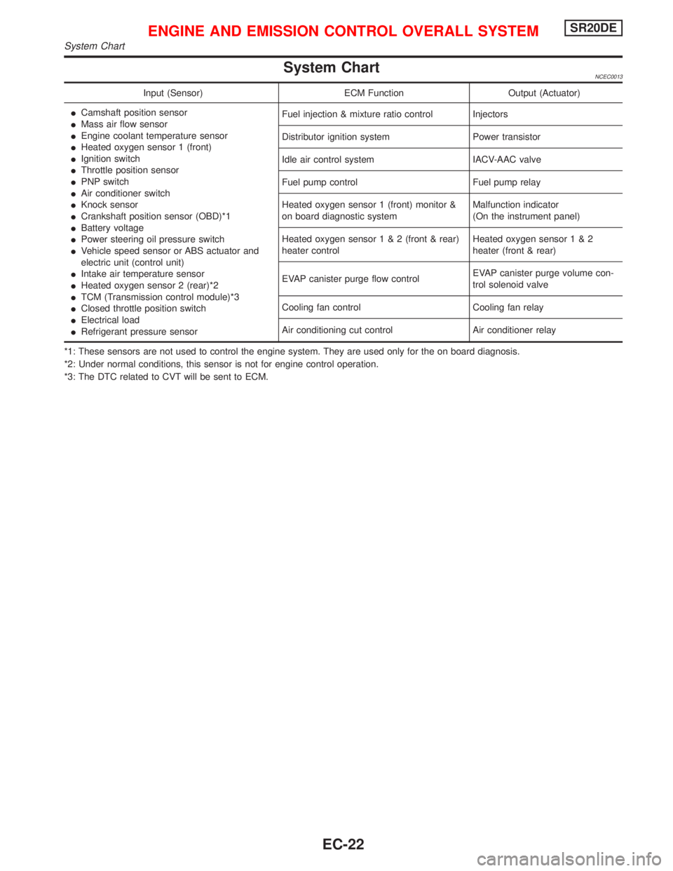
System ChartNCEC0013
Input (Sensor) ECM Function Output (Actuator)
ICamshaft position sensor
IMass air flow sensor
IEngine coolant temperature sensor
IHeated oxygen sensor 1 (front)
IIgnition switch
IThrottle position sensor
IPNP switch
IAir conditioner switch
IKnock sensor
ICrankshaft position sensor (OBD)*1
IBattery voltage
IPower steering oil pressure switch
IVehicle speed sensor or ABS actuator and
electric unit (control unit)
IIntake air temperature sensor
IHeated oxygen sensor 2 (rear)*2
ITCM (Transmission control module)*3
IClosed throttle position switch
IElectrical load
IRefrigerant pressure sensorFuel injection & mixture ratio control Injectors
Distributor ignition system Power transistor
Idle air control system IACV-AAC valve
Fuel pump control Fuel pump relay
Heated oxygen sensor 1 (front) monitor &
on board diagnostic systemMalfunction indicator
(On the instrument panel)
Heated oxygen sensor1&2(front & rear)
heater controlHeated oxygen sensor1&2
heater (front & rear)
EVAP canister purge flow controlEVAP canister purge volume con-
trol solenoid valve
Cooling fan control Cooling fan relay
Air conditioning cut control Air conditioner relay
*1: These sensors are not used to control the engine system. They are used only for the on board diagnosis.
*2: Under normal conditions, this sensor is not for engine control operation.
*3: The DTC related to CVT will be sent to ECM.
ENGINE AND EMISSION CONTROL OVERALL SYSTEMSR20DE
System Chart
EC-22