low oil pressure NISSAN PRIMERA 1999 Electronic Service Manual
[x] Cancel search | Manufacturer: NISSAN, Model Year: 1999, Model line: PRIMERA, Model: NISSAN PRIMERA 1999Pages: 2267, PDF Size: 35.74 MB
Page 1667 of 2267
7. Crank engine and read compression gauge indication.
Cranking speed: 200 rpm
Compression pressure: kPa (bar, kg/cm
2, psi)
Standard
3,138 (31.4, 32, 455)
Limit
2,452 (24.5, 25, 356)
Limit of difference between cylinders
490 (4.9, 5, 71)
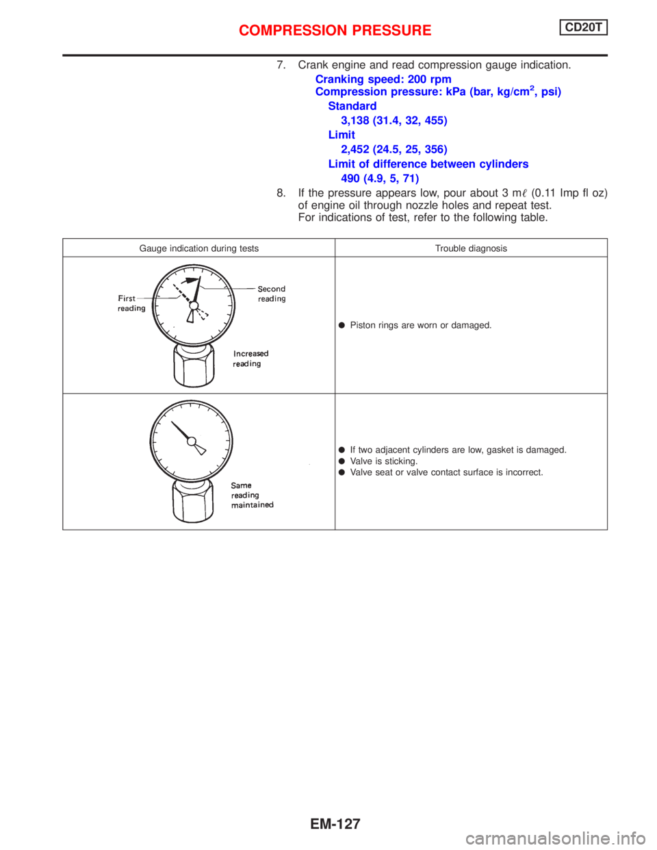
8. If the pressure appears low, pour about 3 m(0.11 Imp fl oz)
of engine oil through nozzle holes and repeat test.
For indications of test, refer to the following table.
Gauge indication during tests Trouble diagnosis
lPiston rings are worn or damaged.
lIf two adjacent cylinders are low, gasket is damaged.
lValve is sticking.
lValve seat or valve contact surface is incorrect.
COMPRESSION PRESSURECD20T
EM-127
Page 1801 of 2267
Precautions for Multiport Fuel Injection
System or Engine Control Module
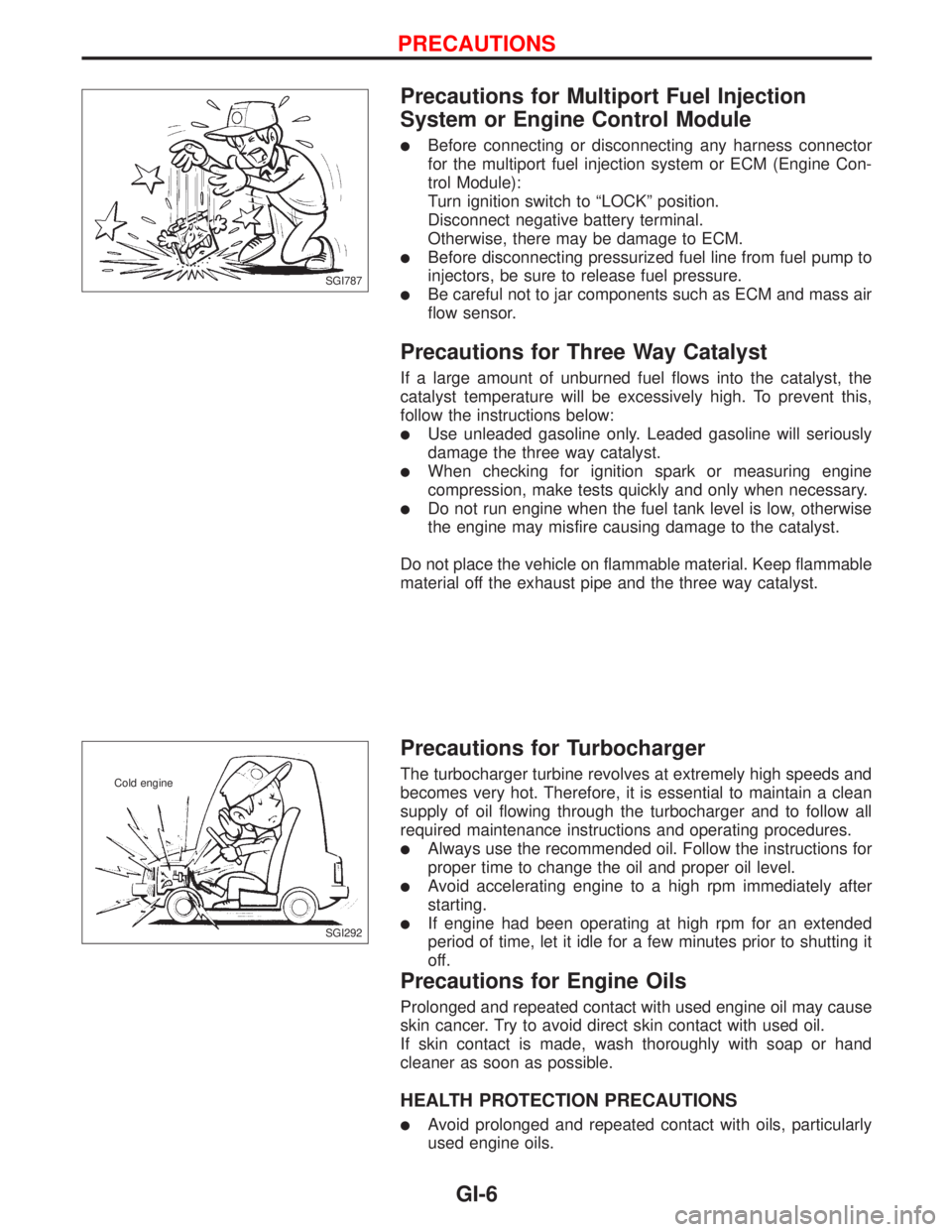
lBefore connecting or disconnecting any harness connector
for the multiport fuel injection system or ECM (Engine Con-
trol Module):
Turn ignition switch to ªLOCKº position.
Disconnect negative battery terminal.
Otherwise, there may be damage to ECM.
lBefore disconnecting pressurized fuel line from fuel pump to
injectors, be sure to release fuel pressure.
lBe careful not to jar components such as ECM and mass air
flow sensor.
Precautions for Three Way Catalyst
If a large amount of unburned fuel flows into the catalyst, the
catalyst temperature will be excessively high. To prevent this,
follow the instructions below:
lUse unleaded gasoline only. Leaded gasoline will seriously
damage the three way catalyst.
lWhen checking for ignition spark or measuring engine
compression, make tests quickly and only when necessary.
lDo not run engine when the fuel tank level is low, otherwise
the engine may misfire causing damage to the catalyst.
Do not place the vehicle on flammable material. Keep flammable
material off the exhaust pipe and the three way catalyst.
Precautions for Turbocharger
The turbocharger turbine revolves at extremely high speeds and
becomes very hot. Therefore, it is essential to maintain a clean
supply of oil flowing through the turbocharger and to follow all
required maintenance instructions and operating procedures.
lAlways use the recommended oil. Follow the instructions for
proper time to change the oil and proper oil level.
lAvoid accelerating engine to a high rpm immediately after
starting.
lIf engine had been operating at high rpm for an extended
period of time, let it idle for a few minutes prior to shutting it
off.
Precautions for Engine Oils
Prolonged and repeated contact with used engine oil may cause
skin cancer. Try to avoid direct skin contact with used oil.
If skin contact is made, wash thoroughly with soap or hand
cleaner as soon as possible.
HEALTH PROTECTION PRECAUTIONS
lAvoid prolonged and repeated contact with oils, particularly
used engine oils.
SGI787
SGI292 Cold engine
PRECAUTIONS
GI-6
Page 1815 of 2267
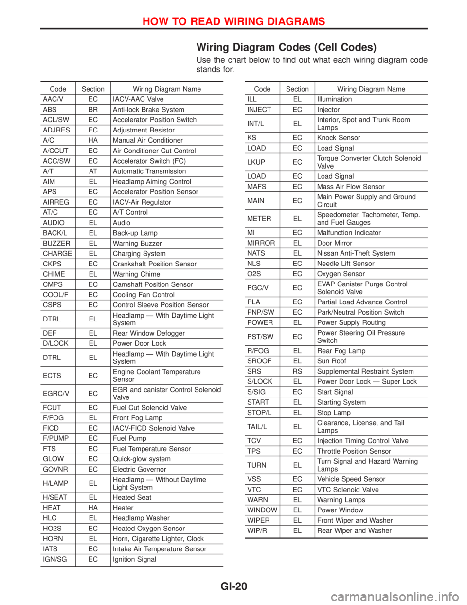
Wiring Diagram Codes (Cell Codes)
Use the chart below to find out what each wiring diagram code
stands for.
Code Section Wiring Diagram Name
AAC/V EC IACV-AAC Valve
ABS BR Anti-lock Brake System
ACL/SW EC Accelerator Position Switch
ADJRES EC Adjustment Resistor
A/C HA Manual Air Conditioner
A/CCUT EC Air Conditioner Cut Control
ACC/SW EC Accelerator Switch (FC)
A/T AT Automatic Transmission
AIM EL Headlamp Aiming Control
APS EC Accelerator Position Sensor
AIRREG EC IACV-Air Regulator
AT/C EC A/T Control
AUDIO EL Audio
BACK/L EL Back-up Lamp
BUZZER EL Warning Buzzer
CHARGE EL Charging System
CKPS EC Crankshaft Position Sensor
CHIME EL Warning Chime
CMPS EC Camshaft Position Sensor
COOL/F EC Cooling Fan Control
CSPS EC Control Sleeve Position Sensor
DTRL ELHeadlamp Ð With Daytime Light
System
DEF EL Rear Window Defogger
D/LOCK EL Power Door Lock
DTRL ELHeadlamp Ð With Daytime Light
System
ECTS ECEngine Coolant Temperature
Sensor
EGRC/V ECEGR and canister Control Solenoid
Valve
FCUT EC Fuel Cut Solenoid Valve
F/FOG EL Front Fog Lamp
FICD EC IACV-FICD Solenoid Valve
F/PUMP EC Fuel Pump
FTS EC Fuel Temperature Sensor
GLOW EC Quick-glow system
GOVNR EC Electric Governor
H/LAMP ELHeadlamp Ð Without Daytime
Light System
H/SEAT EL Heated Seat
HEAT HA Heater
HLC EL Headlamp Washer
HO2S EC Heated Oxygen Sensor
HORN EL Horn, Cigarette Lighter, Clock
IATS EC Intake Air Temperature Sensor
IGN/SG EC Ignition SignalCode Section Wiring Diagram Name
ILL EL Illumination
INJECT EC Injector
INT/L ELInterior, Spot and Trunk Room
Lamps
KS EC Knock Sensor
LOAD EC Load Signal
LKUP ECTorque Converter Clutch Solenoid
Valve
LOAD EC Load Signal
MAFS EC Mass Air Flow Sensor
MAIN ECMain Power Supply and Ground
Circuit
METER ELSpeedometer, Tachometer, Temp.
and Fuel Gauges
MI EC Malfunction Indicator
MIRROR EL Door Mirror
NATS EL Nissan Anti-Theft System
NLS EC Needle Lift Sensor
O2S EC Oxygen Sensor
PGC/V ECEVAP Canister Purge Control
Solenoid Valve
PLA EC Partial Load Advance Control
PNP/SW EC Park/Neutral Position Switch
POWER EL Power Supply Routing
PST/SW ECPower Steering Oil Pressure
Switch
R/FOG EL Rear Fog Lamp
SROOF EL Sun Roof
SRS RS Supplemental Restraint System
S/LOCK EL Power Door Lock Ð Super Lock
S/SIG EC Start Signal
START EL Starting System
STOP/L EL Stop Lamp
TAIL/L ELClearance, License, and Tail
Lamps
TCV EC Injection Timing Control Valve
TPS EC Throttle Position Sensor
TURN ELTurn Signal and Hazard Warning
Lamps
VSS EC Vehicle Speed Sensor
VTC EC VTC Solenoid Valve
WARN EL Warning Lamps
WINDOW EL Power Window
WIPER EL Front Wiper and Washer
WIP/R EL Rear Wiper and Washer
HOW TO READ WIRING DIAGRAMS
GI-20
Page 1855 of 2267
WARNING:
Make sure all refrigerant is discharged into the recycling equipment and the pressure in the system
is less than atmospheric pressure. Then gradually loosen the discharge side hose fitting and remove
it.
CAUTION:
When replacing or cleaning refrigerant cycle components, observe the following:
lWhen the compressor is removed, store it in the same position as it is when mounted on the car.
Failure to do so will cause lubricant to enter the low pressure chamber.
lWhen connecting tubes, always use a torque wrench and a back-up wrench.
lAfter disconnecting tubes, immediately plug all openings to prevent entry of dirt and moisture.
lWhen installing an air conditioner in the vehicle, connect the pipes as the final stage of the
operation. Do not remove the seal caps of pipes and other components until just before connec-
tion.
lAllow components stored in cool areas to warm to ambient temperature before removing seal
caps. This prevents condensation from forming inside A/C components.
lThoroughly remove moisture from the refrigeration system before charging the refrigerant.
lAlways replace used O-rings.
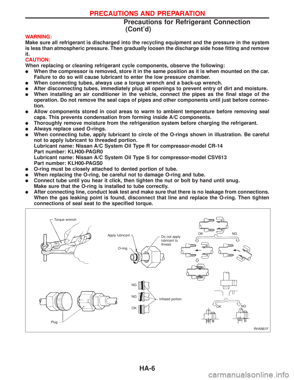
lWhen connecting tube, apply lubricant to circle of the O-rings shown in illustration. Be careful
not to apply lubricant to threaded portion.
Lubricant name: Nissan A/C System Oil Type R for compressor-model CR-14
Part number: KLH00-PAGR0
Lubricant name: Nissan A/C System Oil Type S for compressor-model CSV613
Part number: KLH00-PAGS0
lO-ring must be closely attached to dented portion of tube.
lWhen replacing the O-ring, be careful not to damage O-ring and tube.
lConnect tube until you hear it click, then tighten the nut or bolt by hand until snug.
Make sure that the O-ring is installed to tube correctly.
lAfter connecting line, conduct leak test and make sure that there is no leakage from connections.
When the gas leaking point is found, disconnect that line and replace the O-ring. Then tighten
connections of seal seat to the specified torque.
RHA861F Torque wrench
Apply lubricant
Do not apply
lubricant to
thread.NG OK
NG
OK Inflated portion NG
NG
OK
PlugO-ring
PRECAUTIONS AND PREPARATION
Precautions for Refrigerant Connection
(Cont'd)
HA-6
Page 1859 of 2267
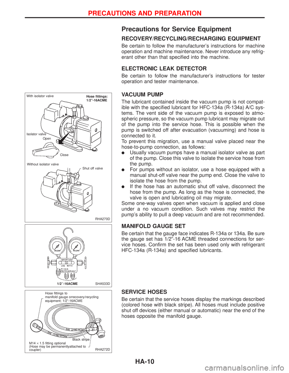
Precautions for Service Equipment
RECOVERY/RECYCLING/RECHARGING EQUIPMENT
Be certain to follow the manufacturer's instructions for machine
operation and machine maintenance. Never introduce any refrig-
erant other than that specified into the machine.
ELECTRONIC LEAK DETECTOR
Be certain to follow the manufacturer's instructions for tester
operation and tester maintenance.
VACUUM PUMP
The lubricant contained inside the vacuum pump is not compat-
ible with the specified lubricant for HFC-134a (R-134a) A/C sys-
tems. The vent side of the vacuum pump is exposed to atmo-
spheric pressure, so the vacuum pump lubricant may migrate out
of the pump into the service hose. This is possible when the
pump is switched off after evacuation (vacuuming) and hose is
connected to it.
To prevent this migration, use a manual valve placed near the
hose-to-pump connection, as follows:
lUsually vacuum pumps have a manual isolator valve as part
of the pump. Close this valve to isolate the service hose from
the pump.
lFor pumps without an isolator, use a hose equipped with a
manual shut-off valve near the pump end. Close the valve to
isolate the hose from the pump.
lIf the hose has an automatic shut off valve, disconnect the
hose from the pump. As long as the hose is connected, the
valve is open and lubricating oil may migrate.
Some one-way valves open when vacuum is applied and close
under a no vacuum condition. Such valves may restrict the
pump's ability to pull a deep vacuum and are not recommended.
MANIFOLD GAUGE SET
Be certain that the gauge face indicates R-134a or 134a. Be sure
the gauge set has 1/2º-16 ACME threaded connections for ser-
vice hoses. Confirm the set has been used only with refrigerant
HFC-134a (R-134a) and specified lubricants.
SERVICE HOSES
Be certain that the service hoses display the markings described
(colored hose with black stripe). All hoses must include positive
shut off devices (either manual or automatic) near the end of the
hoses opposite the manifold gauge.
RHA270D With isolator valve
Hose fittings:
1/2º-16ACME
Close
Shut off valve Isolator valve
Open
Without isolator valve
SHA533D
1/2¢¢-16ACME
RHA272D Hose fittings to
manifold gauge orrecovery/recycling
equipment; 1/2º-16ACME
Black stripe
M14´1.5 fitting optional
(Hose may be permanentlyattached to
coupler)
PRECAUTIONS AND PREPARATION
HA-10
Page 1861 of 2267
Refrigeration Cycle
REFRIGERANT FLOW
The refrigerant flow is in the standard pattern. Refrigerant flows through the compressor, condenser, liquid
tank, evaporator, and back to the compressor.
The refrigerant evaporation through the evaporator coil is controlled by an externally equalized expansion
valve, located inside the evaporator case.
FREEZE PROTECTION
Variable displacement (CSV613)
Under normal operating conditions, when the A/C is switched on, the compressor runs continuously, and the
evaporator pressure, therefore temperature, is controlled by the CSV613 variable displacement compressor
to prevent freeze up.
Vane rotary (CR-14)
The compressor cycles on and off to maintain the evaporator temperature within a specified range. When
the evaporator coil temperature falls below a specified point, the thermo control amplifier interrupts the
compressor operation. When the evaporator coil temperature rises above the specification, the thermo con-
trol amplifier allows compressor operation.
REFRIGERANT SYSTEM PROTECTION
Dual-pressure switch (System with CR-14 compressor)
The refrigerant system is protected against excessively high or low pressure by the dual-pressure switch,
located on the liquid tank. If the system pressure rises above, or falls below the specifications, the dual-
pressure switch opens to interrupt the compressor operation.
Pressure sensor (System with CSV613 compressor)
The pressure sensor is located on the liquid tank. It converts the system pressure into a voltage value witch
is then input into ECM.
If the system pressure rises above, or falls below the specifications, ECM interrupt the compressor opera-
tion.
Fusible plug
Open at temperatures above 105ÉC (221ÉF), thereby discharging refrigerant to the atmosphere. If this plug
is melted and opened, check the refrigerant line and replace liquid tank.
Pressure relief valve (CSV613 compressor)
The refrigerant system is also protected by a pressure relief valve, located in the rear head of the compres-
sor. When the pressure of refrigerant in the system increases to an abnormal level [more than 3,727 kPa
(38 kg/cm
2, 540 psi)], the release port on the pressure relief valve automatically opens and releases refrig-
erant into the atmosphere.
DESCRIPTION
HA-12
Page 1880 of 2267
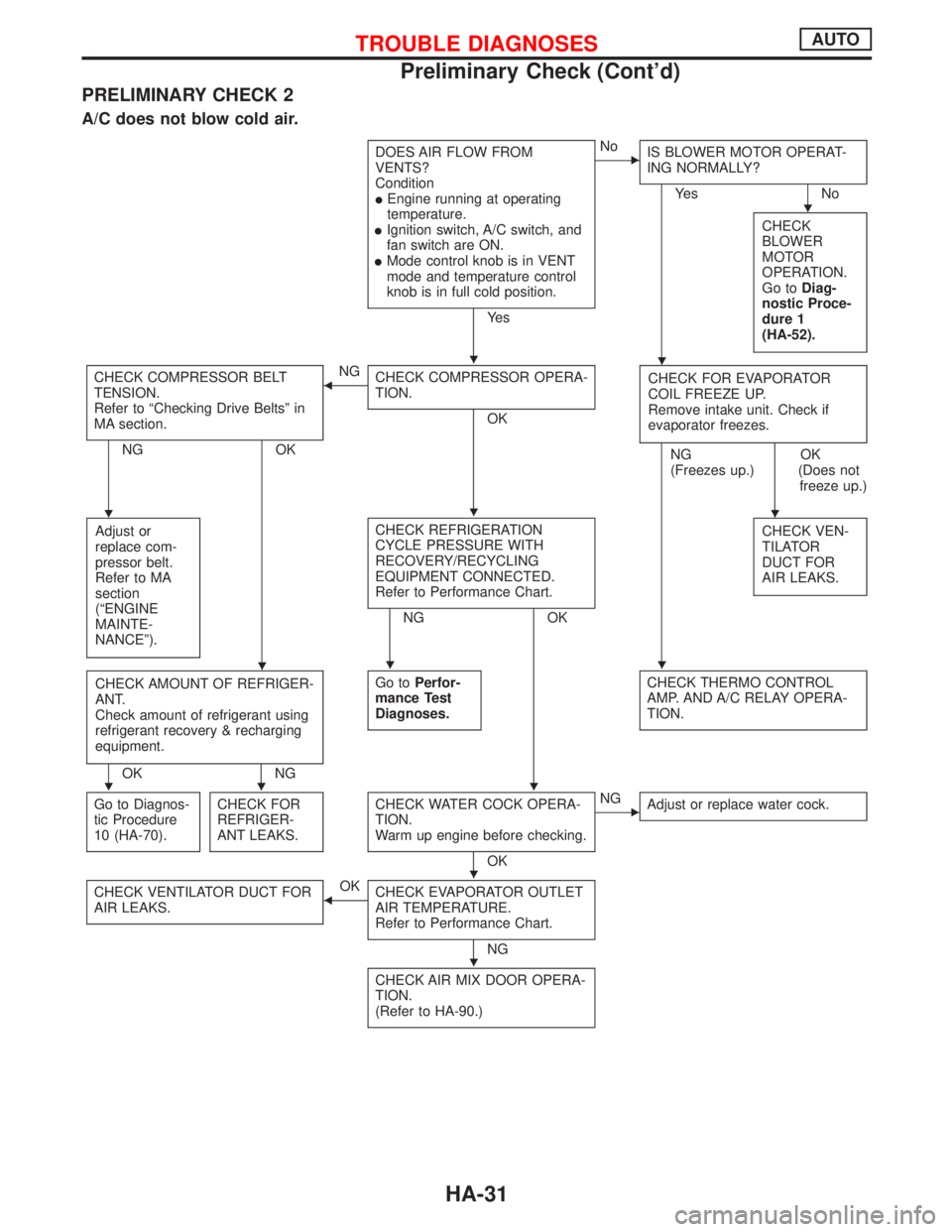
PRELIMINARY CHECK 2
A/C does not blow cold air.
DOES AIR FLOW FROM
VENTS?
Condition
lEngine running at operating
temperature.
lIgnition switch, A/C switch, and
fan switch are ON.
lMode control knob is in VENT
mode and temperature control
knob is in full cold position.
Ye s
ENo
IS BLOWER MOTOR OPERAT-
ING NORMALLY?
Ye s N o
CHECK
BLOWER
MOTOR
OPERATION.
Go toDiag-
nostic Proce-
dure 1
(HA-52).
CHECK COMPRESSOR BELT
TENSION.
Refer to ªChecking Drive Beltsº in
MA section.
NG OK
FNG
CHECK COMPRESSOR OPERA-
TION.
OKCHECK FOR EVAPORATOR
COIL FREEZE UP.
Remove intake unit. Check if
evaporator freezes.
NG
(Freezes up.)OK
(Does not
freeze up.)
Adjust or
replace com-
pressor belt.
Refer to MA
section
(ªENGINE
MAINTE-
NANCEº).
CHECK REFRIGERATION
CYCLE PRESSURE WITH
RECOVERY/RECYCLING
EQUIPMENT CONNECTED.
Refer to Performance Chart.
NG OKCHECK VEN-
TILATOR
DUCT FOR
AIR LEAKS.
CHECK AMOUNT OF REFRIGER-
ANT.
Check amount of refrigerant using
refrigerant recovery & recharging
equipment.
OK NGGo toPerfor-
mance Test
Diagnoses.
CHECK THERMO CONTROL
AMP. AND A/C RELAY OPERA-
TION.
Go to Diagnos-
tic Procedure
10 (HA-70).CHECK FOR
REFRIGER-
ANT LEAKS.CHECK WATER COCK OPERA-
TION.
Warm up engine before checking.
OK
ENG
Adjust or replace water cock.
CHECK VENTILATOR DUCT FOR
AIR LEAKS.FOK
CHECK EVAPORATOR OUTLET
AIR TEMPERATURE.
Refer to Performance Chart.
NG
CHECK AIR MIX DOOR OPERA-
TION.
(Refer to HA-90.)
H
HH
HHH
HHH
HHH
H
H
TROUBLE DIAGNOSESAUTO
Preliminary Check (Cont'd)
HA-31
Page 1883 of 2267
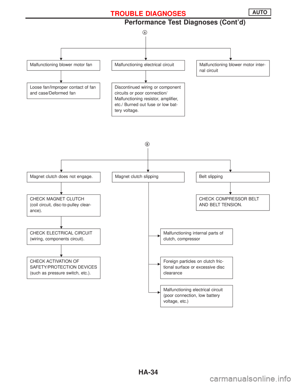
pA
Malfunctioning blower motor fanMalfunctioning electrical circuitMalfunctioning blower motor inter-
nal circuit
Loose fan/Improper contact of fan
and case/Deformed fanDiscontinued wiring or component
circuits or poor connection/
Malfunctioning resistor, amplifier,
etc./ Burned out fuse or low bat-
tery voltage.
pB
Magnet clutch does not engage.Magnet clutch slippingBelt slipping
CHECK MAGNET CLUTCH
(coil circuit, disc-to-pulley clear-
ance).CHECK COMPRESSOR BELT
AND BELT TENSION.
CHECK ELECTRICAL CIRCUIT
(wiring, components circuit).EMalfunctioning internal parts of
clutch, compressor
CHECK ACTIVATION OF
SAFETY/PROTECTION DEVICES
(such as pressure switch, etc.).EForeign particles on clutch fric-
tional surface or excessive disc
clearance
EMalfunctioning electrical circuit
(poor connection, low battery
voltage, etc.)
HHH
HH
HHH
HH
H
H
TROUBLE DIAGNOSESAUTO
Performance Test Diagnoses (Cont'd)
HA-34
Page 1919 of 2267
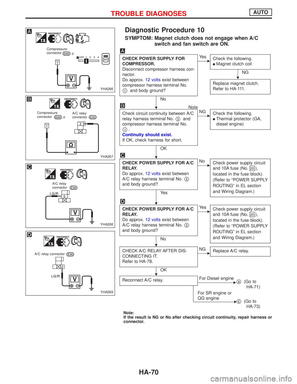
Diagnostic Procedure 10
SYMPTOM: Magnet clutch does not engage when A/C
switch and fan switch are ON.
CHECK POWER SUPPLY FOR
COMPRESSOR.
Disconnect compressor harness con-
nector.
Do approx.12 voltsexist between
compressor harness terminal No.
p1and body ground?
No
EYe s
Check the following.
lMagnet clutch coil
NG
Replace magnet clutch.
Refer to HA-111.
Note
Check circuit continuity between A/C
relay harness terminal No.
p3and
compressor harness terminal No.
p1.
Continuity should exist.
If OK, check harness for short.
OK
ENG
Check the following.
lThermal protector (GA,
diesel engine)
CHECK POWER SUPPLY FOR A/C
RELAY.
Do approx.12 voltsexist between
A/C relay harness terminal No.
p5
and body ground?
Ye s
ENo
Check power supply circuit
and 10A fuse (No.
20),
located in the fuse block).
(Refer to ªPOWER SUPPLY
ROUTINGº in EL section
and Wiring Diagram.)
CHECK POWER SUPPLY FOR A/C
RELAY.
Do approx.12 voltsexist between
A/C relay harness terminal No.
p2
and body ground?
No
EYe s
Check power supply circuit
and 10A fuse (No.
20),
located in the fuse block).
(Refer to ªPOWER SUPPLY
ROUTINGº in EL section
and Wiring Diagram.)
CHECK A/C RELAY AFTER DIS-
CONNECTING IT.
Refer to HA-78.
OK
ENG
Replace A/C relay.
Reconnect A/C relay.EFor Diesel enginepA(Go to
HA-71)
E
For SR engine or
QG engine
pC(Go to
HA-73)
Note:
If the result is NG or No after checking circuit continuity, repair harness or
connector.
YHA266
Compressure
connector
YHA267
Compressure
connectorA/C relay
connector
YHA268
A/C relay
connector
YHA269
A/C relay connector
H
H
H
H
H
H
TROUBLE DIAGNOSESAUTO
HA-70
Page 1951 of 2267
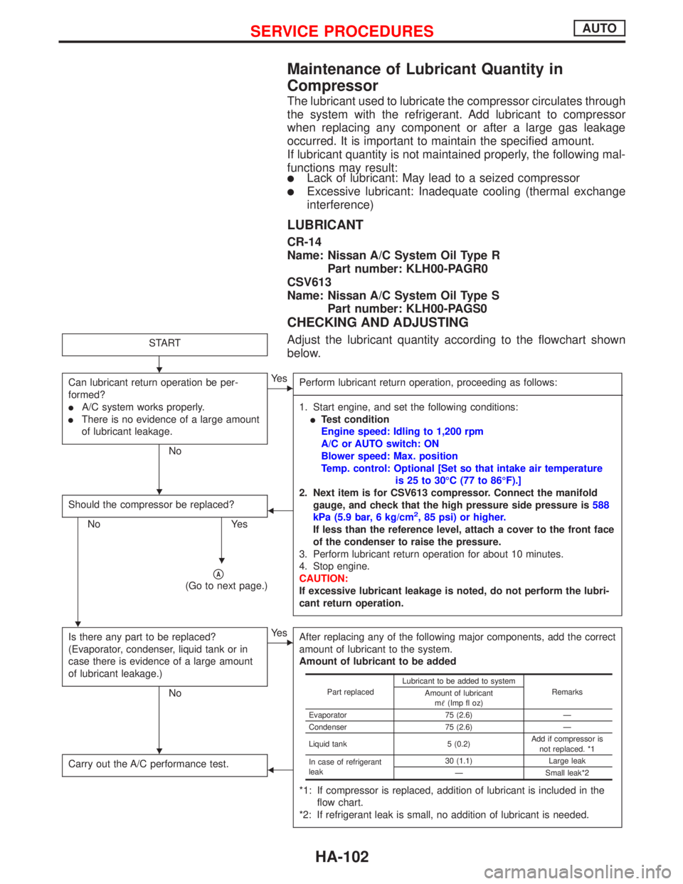
Maintenance of Lubricant Quantity in
Compressor
The lubricant used to lubricate the compressor circulates through
the system with the refrigerant. Add lubricant to compressor
when replacing any component or after a large gas leakage
occurred. It is important to maintain the specified amount.
If lubricant quantity is not maintained properly, the following mal-
functions may result:
lLack of lubricant: May lead to a seized compressor
lExcessive lubricant: Inadequate cooling (thermal exchange
interference)
LUBRICANT
CR-14
Name: Nissan A/C System Oil Type R
Part number: KLH00-PAGR0
CSV613
Name: Nissan A/C System Oil Type S
Part number: KLH00-PAGS0
CHECKING AND ADJUSTING
Adjust the lubricant quantity according to the flowchart shown
below.START
Can lubricant return operation be per-
formed?
lA/C system works properly.
lThere is no evidence of a large amount
of lubricant leakage.
No
EYe s
Perform lubricant return operation, proceeding as follows:
------------------------------------------------------------------------------------------------------------------------------------------------------------------------------------------------------------------------------------------------------------------------------------------------------------------------------------------------------------------------------------------------------------------------------------------------------------------------------------------------------------------------------------
1. Start engine, and set the following conditions:
lTest condition
Engine speed: Idling to 1,200 rpm
A/C or AUTO switch: ON
Blower speed: Max. position
Temp. control: Optional [Set so that intake air temperature
is 25 to 30ÉC (77 to 86ÉF).]
2. Next item is for CSV613 compressor. Connect the manifold
gauge, and check that the high pressure side pressure is588
kPa (5.9 bar, 6 kg/cm
2, 85 psi) or higher.
If less than the reference level, attach a cover to the front face
of the condenser to raise the pressure.
3. Perform lubricant return operation for about 10 minutes.
4. Stop engine.
CAUTION:
If excessive lubricant leakage is noted, do not perform the lubri-
cant return operation.
Should the compressor be replaced?
No Yes
F
pA
(Go to next page.)
Is there any part to be replaced?
(Evaporator, condenser, liquid tank or in
case there is evidence of a large amount
of lubricant leakage.)
No
EYe s
After replacing any of the following major components, add the correct
amount of lubricant to the system.
Amount of lubricant to be added
*1: If compressor is replaced, addition of lubricant is included in the
flow chart.
*2: If refrigerant leak is small, no addition of lubricant is needed.
Carry out the A/C performance test.F
Part replacedLubricant to be added to system
Remarks
Amount of lubricant
m(Imp fl oz)
Evaporator 75 (2.6) Ð
Condenser 75 (2.6) Ð
Liquid tank 5 (0.2)Add if compressor is
not replaced. *1
In case of refrigerant
leak30 (1.1) Large leak
Ð Small leak*2
H
H
H
H
H
SERVICE PROCEDURESAUTO
HA-102