lock NISSAN PRIMERA 1999 Electronic Repair Manual
[x] Cancel search | Manufacturer: NISSAN, Model Year: 1999, Model line: PRIMERA, Model: NISSAN PRIMERA 1999Pages: 2267, PDF Size: 35.74 MB
Page 2183 of 2267
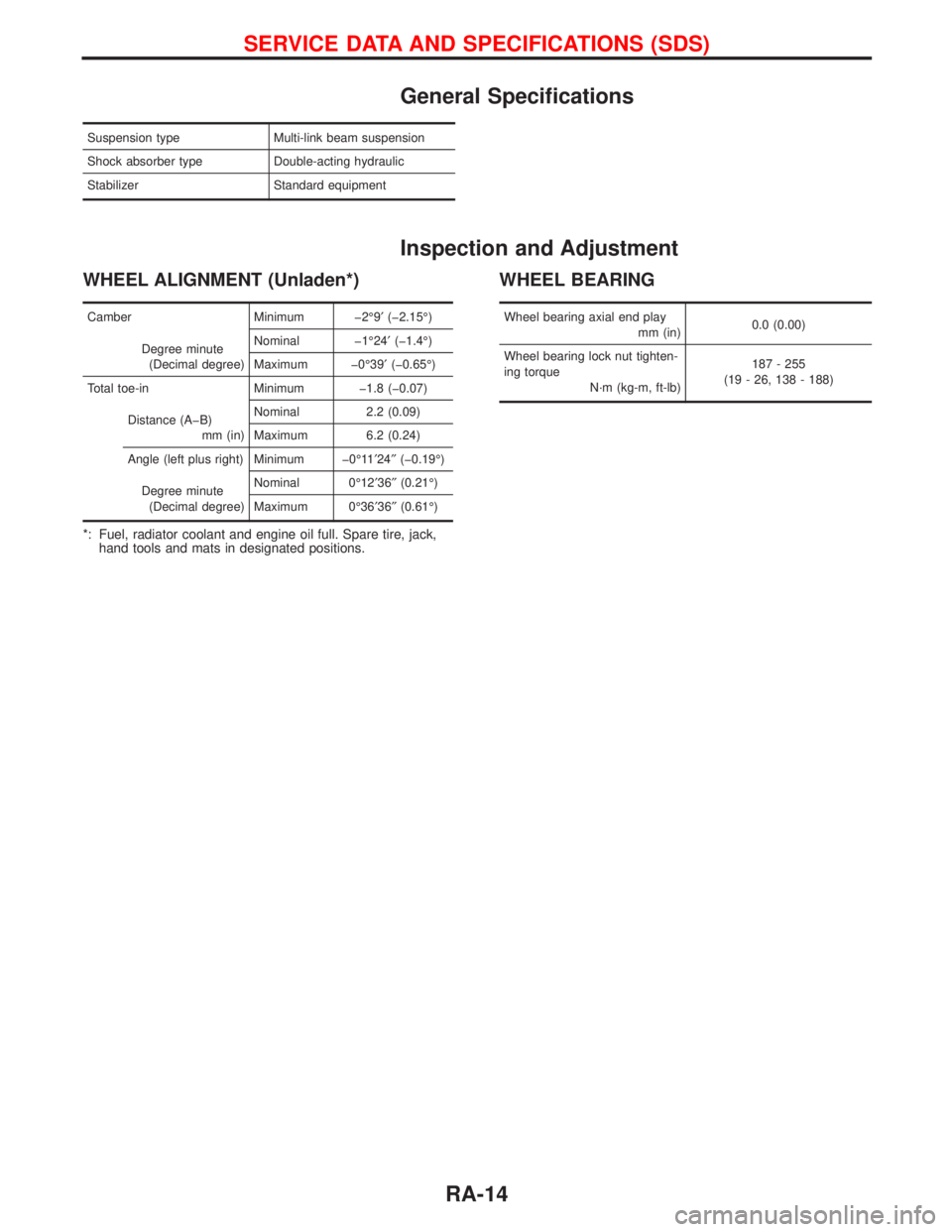
General Specifications
Suspension type Multi-link beam suspension
Shock absorber type Double-acting hydraulic
Stabilizer Standard equipment
Inspection and Adjustment
WHEEL ALIGNMENT (Unladen*)
Camber Minimum þ2É9¢(þ2.15É)
Degree minute
(Decimal degree)Nominal þ1É24¢(þ1.4É)
Maximum þ0É39¢(þ0.65É)
Total toe-in Minimum þ1.8 (þ0.07)
Distance (AþB)
mm (in)Nominal 2.2 (0.09)
Maximum 6.2 (0.24)
Angle (left plus right) Minimum þ0É11¢24²(þ0.19É)
Degree minute
(Decimal degree)Nominal 0É12¢36²(0.21É)
Maximum 0É36¢36²(0.61É)
*: Fuel, radiator coolant and engine oil full. Spare tire, jack,
hand tools and mats in designated positions.
WHEEL BEARING
Wheel bearing axial end play
mm (in)0.0 (0.00)
Wheel bearing lock nut tighten-
ing torque
N´m (kg-m, ft-lb)187 - 255
(19 - 26, 138 - 188)
SERVICE DATA AND SPECIFICATIONS (SDS)
RA-14
Page 2189 of 2267
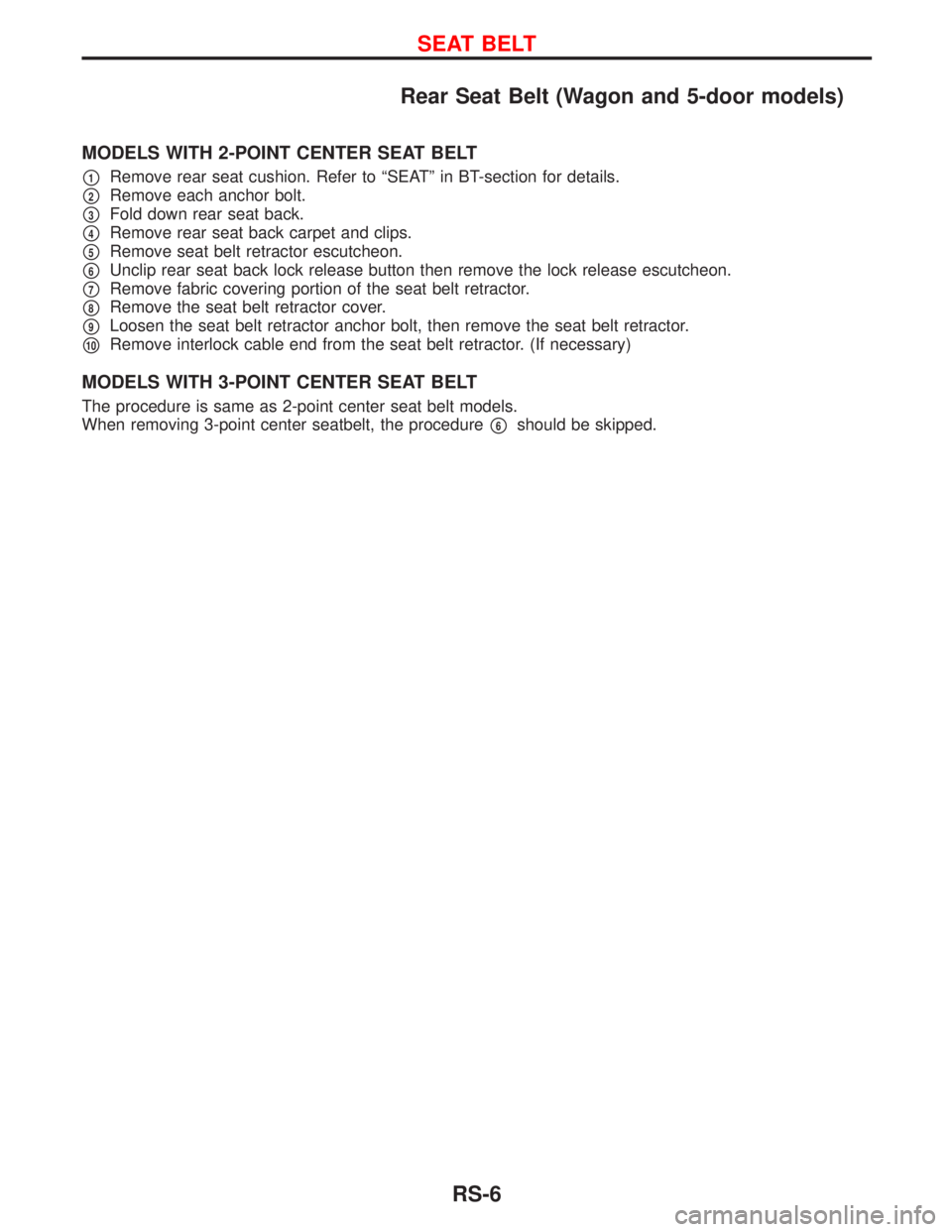
Rear Seat Belt (Wagon and 5-door models)
MODELS WITH 2-POINT CENTER SEAT BELT
p1Remove rear seat cushion. Refer to ªSEATº in BT-section for details.
p2Remove each anchor bolt.
p3Fold down rear seat back.
p4Remove rear seat back carpet and clips.
p5Remove seat belt retractor escutcheon.
p6Unclip rear seat back lock release button then remove the lock release escutcheon.
p7Remove fabric covering portion of the seat belt retractor.
p8Remove the seat belt retractor cover.
p9Loosen the seat belt retractor anchor bolt, then remove the seat belt retractor.
p10Remove interlock cable end from the seat belt retractor. (If necessary)
MODELS WITH 3-POINT CENTER SEAT BELT
The procedure is same as 2-point center seat belt models.
When removing 3-point center seatbelt, the procedure
p6should be skipped.
SEAT BELT
RS-6
Page 2199 of 2267

7. Disconnect connector and remove the four screws. The spi-
ral cable can then be removed.
CAUTION:
lDo not attempt to disassemble spiral cable.
lDo not apply lubricant to the spiral cable.
Installation Ð Air Bag Module and Spiral
Cable
1. Set the front wheels in the straight-ahead position.
2. Make sure that the spiral cable is in the neutral position. The
neutral position is detected by turning left (clock wise) about
3.5 revolutions from the right end position. Align the two
marks (
) or make sure the white indicator is visible in the
upper part of the indicator window, with the cable pointed
down wards.
CAUTION:
lThe spiral cable may snap during steering operation if
the cable is installed incorrectly.
lAlso, with the steering linkage disconnected, the cable
may snap by turning the steering wheel beyond the lim-
ited number of turns.
(The spiral cable can be turned up to 3.5 turns from the
neutral position to both the right and left.)
3. Connect spiral cable connector and tighten with screws.
Install steering column cover.
4. Install steering wheel setting spiral cable pin guides, and pull
spiral cable through.
5. Connect horn connector and engage spiral cable with pawls
in steering wheel. Move other connectors away from steer-
ing wheel lower lid opener.
6. Tighten nut.
: 29 - 39 N´m (3.0 - 4.0 kg-m, 22 - 29 ft-lb)
7. Position the driver's air bag module and tighten with new
special bolts.
lAlways service the air bag module from the side.
8. Connect other connectors.
9. Install all lids and steering switch (where fitted).
10. Connect both battery cables.
11. Conduct self-diagnosis to ensure entire SRS operates prop-
erly. (Use CONSULT-II or warning lamp check.)
12. Turn steering wheel to the left end and then to the right end
fully to make sure that spiral cable is set in the neutral posi-
tion.
SRS384 Unlock
LockConnector
NRS121
Neutral
positionRight end
Indicator not
visible
Indicator win-
dow
Indicator is vis-
ible
Indicator
window
SRS076
SBF812EA Special bolt
7.8 - 13.7 N´m
(0.8 - 1.4 kg-m,
57 - 99 ft-lb)
SUPPLEMENTAL RESTRAINT SYSTEM (SRS)
Removal Ð Air Bag Module and Spiral Cable
(Cont'd)
RS-16
Page 2205 of 2267
Disposal of Air Bag Module and Seat Belt
Pre-tensioner
lBefore disposing of air bag module and seat belt pre-tensioner, or vehicles equipped with such systems,
deploy the systems. If such systems have already been deployed due to an accident, dispose of as
indicated in ªDISPOSING OF AIR BAG MODULE AND SEAT BELT PRE-TENSIONERº (RS-27).
lWhen deploying the air bag module and seat belt pre-tensioner, always use the Special Service Tool;
Deployment tool KV99106400.
lWhen deploying the air bag module and seat belt pre-tensioner, stand at least 5 m (16 ft) away from
deployment component.
lWhen deploying air bag module and seat belt pre-tensioner a fairly loud noise is made, followed by
smoke being released. The smoke is not poisonous, however, be careful not to inhale smoke since it
irritates the throat and can cause choking.
lAlways activate one air bag module at a time.
lDue to heat, leave air bag module unattended for more than 30 minutes after deployment. Also leave
seat belt pre-tensioner unattended for more than 10 minutes after deployment.
lBe sure to wear gloves when handling a deployed air bag module and seat belt pre-tensioner.
lNever apply water to a deployed air bag module and seat belt pre-tensioner.
lWash your hands clean after finishing work.
lPlace the vehicle outdoors with an open space of at least 6 m (20 ft) on all sides when deploying air
bag module and seat belt pre-tensioner while mounted in vehicle.
lUse a voltmeter to make sure the vehicle battery is fully charged.
lDo not dispose of the air bag module and seat belt pre-tensioner un-deployed.
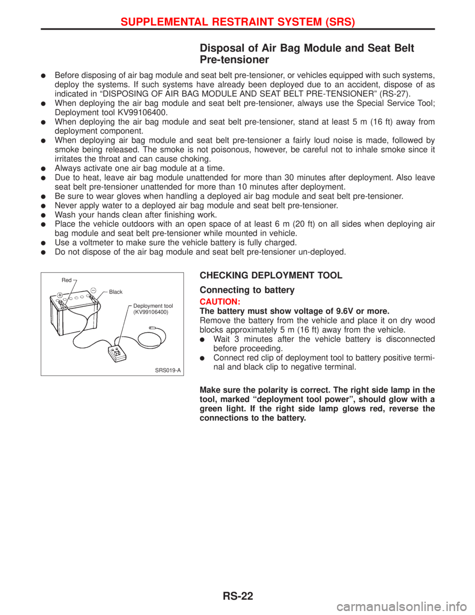
CHECKING DEPLOYMENT TOOL
Connecting to battery
CAUTION:
The battery must show voltage of 9.6V or more.
Remove the battery from the vehicle and place it on dry wood
blocks approximately 5 m (16 ft) away from the vehicle.
lWait 3 minutes after the vehicle battery is disconnected
before proceeding.
lConnect red clip of deployment tool to battery positive termi-
nal and black clip to negative terminal.
Make sure the polarity is correct. The right side lamp in the
tool, marked ªdeployment tool powerº, should glow with a
green light. If the right side lamp glows red, reverse the
connections to the battery.
SRS019-A Red
Black
Deployment tool
(KV99106400)
SUPPLEMENTAL RESTRAINT SYSTEM (SRS)
RS-22
Page 2247 of 2267

NVH Troubleshooting Chart
Use the chart below to help you find the cause of the symptom.
If necessary, repair or replace these parts.
Reference pageST-6
ST-6
ST-18
ST-18
ST-19
ST-6
ST-5
ST-7
Refer to MA section.
Ð
ST-12
ST-5
ST-13
ST-11
ST-14
NVH in FA section
NVH in FA, RA section
NVH in FA section
NCH in FA section
NVH in BR section
Possible cause and
SUSPECTED PARTS
Fluid level
Air in hydraulic system
Tie-rod ball joint swinging force
Tie-rod ball joint rotating torque
Tie-rod ball joint end play
Steering gear fluid leakage
Steering wheel play
Steering wheel turning force
Drive belt looseness
Improper steering wheel
Improper installation or looseness of tilt lock lever
Mounting rubber deterioration
Steering column deformation or damage
Improper installation or looseness of steering column
Steering linkage looseness
DRIVE SHAFT
AXLE AND SUSPENSION
TIRES
ROAD WHEEL
BRAKES
Symptom STEERINGNoiseXXXXXXXXX XXXXX
Shake X X XXXXXX
VibrationXXXXX XXX
Shimmy X X X XXXXX
Judder X XXXXX
X: Applicable
NOISE, VIBRATION AND HARSHNESS (NVH) TROUBLESHOOTING
ST-4
Page 2248 of 2267

Checking Steering Wheel Play
1. With wheels in a straight-ahead position, check steering
wheel play.
Steering wheel play:
35 mm (1.38 in) or less
2. If it is not within specification, check steering gear assembly
when front suspension and axle, steering gear assembly and
steering column are mounted correctly.
Checking Neutral Position on Steering Wheel
Pre-checking
lMake sure that wheel alignment is correct.
Wheel alignment:
Refer to SDS in FA section
lVerify that the steering gear is centered before removing the
steering wheel.
Checking
1. Check that the steering wheel is in the neutral position when
driving straight ahead.
2. If it is not in the neutral position, remove the steering wheel
and reinstall it correctly.
3. If the neutral position is between two serrated teeth, loosen
tie-rod lock nut and move tie-rod in the opposite direction by
the same amount on both left and right sides to compensate
for error in the neutral position.
Front Wheel Turning Angle
1. Rotate steering wheel all the way right and left; measure
turning angle.
Turning angle of full turns:
Refer to SDS in FA section
2. If it is not within specification, check rack stroke.
Rack stroke ªSº:
Refer to SDS (ST-23)
Checking Gear Housing Movement
1. Check the movement of steering gear housing during station-
ary steering on a dry paved surface.
lApply a force of 49 N (5 kg, 11 lb) to steering wheel to check
the gear housing movement.
Turn off ignition key while checking.
Movement of gear housing:
2 mm ( 0.08 in) or less
2. If movement exceeds the limit, replace mount insulator after
confirming correct installation of gear housing clamps.
.SST489B
SST490BA
SMA127
.SST059B
ON-VEHICLE INSPECTION
ST-5
Page 2249 of 2267
Checking and Adjusting Drive Belts
Refer to section MA for Drive Belt Inspection.
Checking Fluid Level
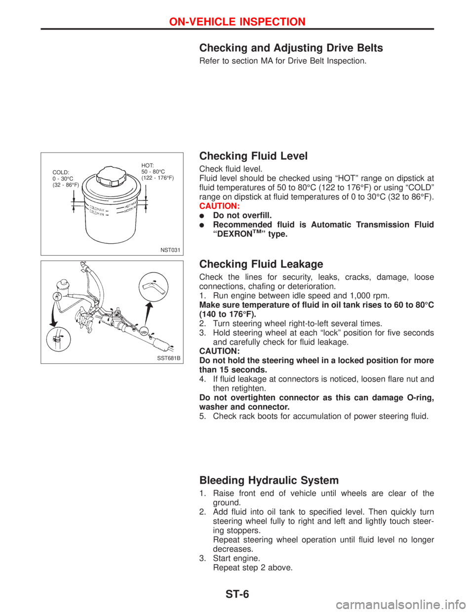
Check fluid level.
Fluid level should be checked using ªHOTº range on dipstick at
fluid temperatures of 50 to 80ÉC (122 to 176ÉF) or using ªCOLDº
range on dipstick at fluid temperatures of 0 to 30ÉC (32 to 86ÉF).
CAUTION:
lDo not overfill.
lRecommended fluid is Automatic Transmission Fluid
ªDEXRONTMº type.
Checking Fluid Leakage
Check the lines for security, leaks, cracks, damage, loose
connections, chafing or deterioration.
1. Run engine between idle speed and 1,000 rpm.
Make sure temperature of fluid in oil tank rises to 60 to 80ÉC
(140 to 176ÉF).
2. Turn steering wheel right-to-left several times.
3. Hold steering wheel at each ªlockº position for five seconds
and carefully check for fluid leakage.
CAUTION:
Do not hold the steering wheel in a locked position for more
than 15 seconds.
4. If fluid leakage at connectors is noticed, loosen flare nut and
then retighten.
Do not overtighten connector as this can damage O-ring,
washer and connector.
5. Check rack boots for accumulation of power steering fluid.
Bleeding Hydraulic System
1. Raise front end of vehicle until wheels are clear of the
ground.
2. Add fluid into oil tank to specified level. Then quickly turn
steering wheel fully to right and left and lightly touch steer-
ing stoppers.
Repeat steering wheel operation until fluid level no longer
decreases.
3. Start engine.
Repeat step 2 above.
NST031 COLD:
0 - 30ÉC
(32 - 86ÉF)HOT:
50 - 80ÉC
(122 - 176ÉF)
SST681B
ON-VEHICLE INSPECTION
ST-6
Page 2251 of 2267
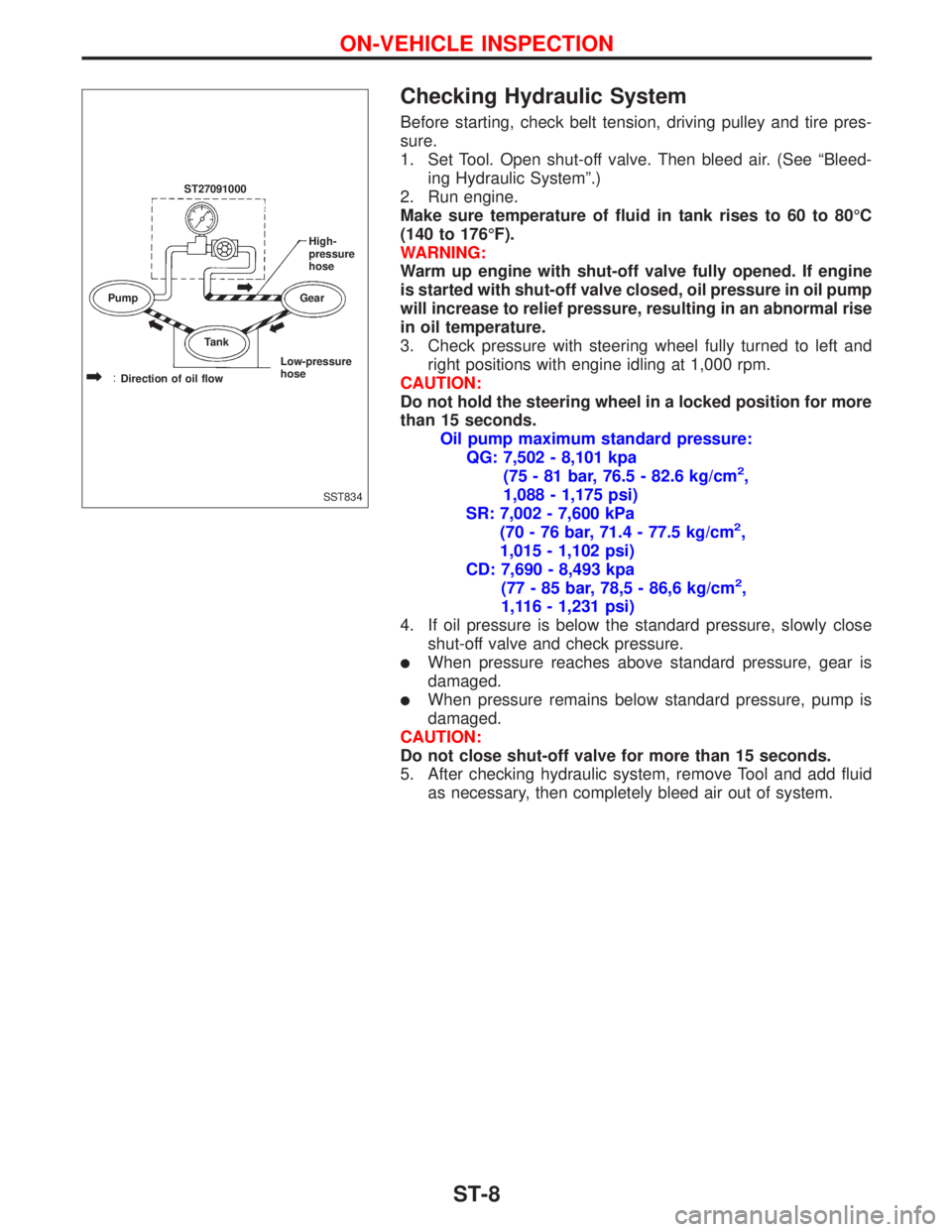
Checking Hydraulic System
Before starting, check belt tension, driving pulley and tire pres-
sure.
1. Set Tool. Open shut-off valve. Then bleed air. (See ªBleed-
ing Hydraulic Systemº.)
2. Run engine.
Make sure temperature of fluid in tank rises to 60 to 80ÉC
(140 to 176ÉF).
WARNING:
Warm up engine with shut-off valve fully opened. If engine
is started with shut-off valve closed, oil pressure in oil pump
will increase to relief pressure, resulting in an abnormal rise
in oil temperature.
3. Check pressure with steering wheel fully turned to left and
right positions with engine idling at 1,000 rpm.
CAUTION:
Do not hold the steering wheel in a locked position for more
than 15 seconds.
Oil pump maximum standard pressure:
QG: 7,502 - 8,101 kpa
(75 - 81 bar, 76.5 - 82.6 kg/cm
2,
1,088 - 1,175 psi)
SR: 7,002 - 7,600 kPa
(70 - 76 bar, 71.4 - 77.5 kg/cm
2,
1,015 - 1,102 psi)
CD: 7,690 - 8,493 kpa
(77 - 85 bar, 78,5 - 86,6 kg/cm
2,
1,116 - 1,231 psi)
4. If oil pressure is below the standard pressure, slowly close
shut-off valve and check pressure.
lWhen pressure reaches above standard pressure, gear is
damaged.
lWhen pressure remains below standard pressure, pump is
damaged.
CAUTION:
Do not close shut-off valve for more than 15 seconds.
5. After checking hydraulic system, remove Tool and add fluid
as necessary, then completely bleed air out of system.
SST834 ST27091000
Pump
TankGearHigh-
pressure
hose
Direction of oil flowLow-pressure
hose
ON-VEHICLE INSPECTION
ST-8
Page 2253 of 2267

Removal and Installation
STEERING WHEEL
lRemove screws from both sides of steering wheel and pull
out horn pad. Refer to RS section for Air Bag Module and
Spiral Cable Removal.
lAlign spiral cable correctly when installing steering wheel.
Refer to RS-section.
STEERING COLUMN
lWhen installing steering column, fingertighten all lower
bracket and clamp retaining bolts; then tighten them
securely. Do not apply undue stress to steering column.
lWhen attaching coupling joint, be sure tightening bolt faces
cutout portion.
lAlign slit of lower joint with projection on dust cover. Insert
joint until surface A contacts surface B.
CAUTION:
After installing steering column, turn steering wheel to make
sure it moves smoothly and that the number of turns from
the straight forward position to left and right locks are equal.
Be sure that the steering wheel is in a neutral position when
driving straight ahead.
NBF004
NST003
SST491C Steering gear
STEERING WHEEL AND STEERING COLUMN
ST-10
Page 2255 of 2267

lEnsure that rounded surface of snap ring faces toward bear-
ing when snap ring is installed.
lInstall snap ring on upper shaft with a suitable tool.
lSteering lock
a. Break self-shear type screws with a drill or other appropriate
tool.
b. Install self-shear type screws and then cut off self-shear type
screw heads.
Inspection
Tilt mechanism
lAfter installing steering column, check tilt mechanism opera-
tion.
SST770A
SST741A
SST742A
SST582B
STEERING WHEEL AND STEERING COLUMN
Disassembly and Assembly (Cont'd)
ST-12