fuel pressure NISSAN PRIMERA 1999 Electronic Repair Manual
[x] Cancel search | Manufacturer: NISSAN, Model Year: 1999, Model line: PRIMERA, Model: NISSAN PRIMERA 1999Pages: 2267, PDF Size: 35.74 MB
Page 221 of 2267
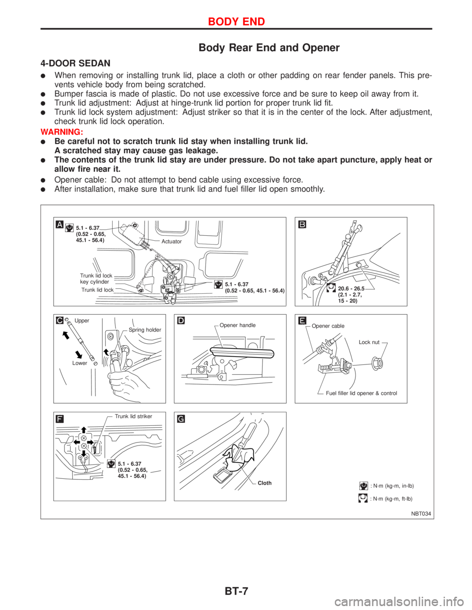
Body Rear End and Opener
4-DOOR SEDAN
lWhen removing or installing trunk lid, place a cloth or other padding on rear fender panels. This pre-
vents vehicle body from being scratched.
lBumper fascia is made of plastic. Do not use excessive force and be sure to keep oil away from it.
lTrunk lid adjustment: Adjust at hinge-trunk lid portion for proper trunk lid fit.
lTrunk lid lock system adjustment: Adjust striker so that it is in the center of the lock. After adjustment,
check trunk lid lock operation.
WARNING:
lBe careful not to scratch trunk lid stay when installing trunk lid.
A scratched stay may cause gas leakage.
lThe contents of the trunk lid stay are under pressure. Do not take apart puncture, apply heat or
allow fire near it.
lOpener cable: Do not attempt to bend cable using excessive force.
lAfter installation, make sure that trunk lid and fuel filler lid open smoothly.
NBT034
5.1 - 6.37
(0.52 - 0.65,
45.1 - 56.4)
Upper
Spring holder
LowerOpener handle
Opener cable
Lock nut
Fuel filler lid opener & control
Trunk lid striker
.5.1 - 6.37
(0.52 - 0.65,
45.1 - 56.4)
: N´m (kg-m, ft-lb)
20.6 - 26.5
(2.1 - 2.7,
15 - 20)
: N´m (kg-m, in-lb) Cloth
Actuator
.Trunk lid lock
key cylinder
.Trunk lid lock
.5.1 - 6.37
(0.52 - 0.65, 45.1 - 56.4)
BODY END
BT-7
Page 223 of 2267
5-DOOR HATCHBACK
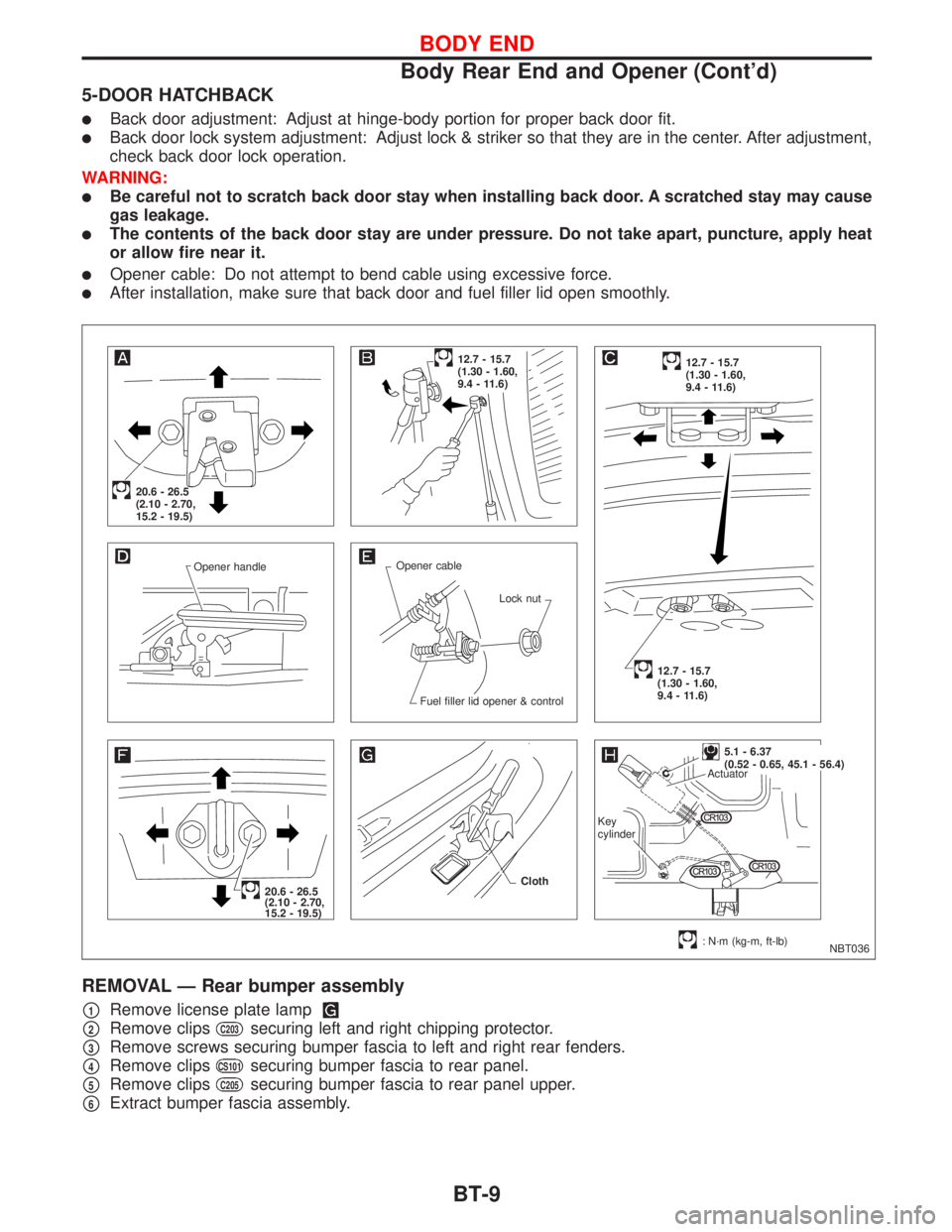
lBack door adjustment: Adjust at hinge-body portion for proper back door fit.
lBack door lock system adjustment: Adjust lock & striker so that they are in the center. After adjustment,
check back door lock operation.
WARNING:
lBe careful not to scratch back door stay when installing back door. A scratched stay may cause
gas leakage.
lThe contents of the back door stay are under pressure. Do not take apart, puncture, apply heat
or allow fire near it.
lOpener cable: Do not attempt to bend cable using excessive force.
lAfter installation, make sure that back door and fuel filler lid open smoothly.
REMOVAL Ð Rear bumper assembly
p1Remove license plate lamp
p2Remove clipsC203securing left and right chipping protector.
p3Remove screws securing bumper fascia to left and right rear fenders.
p4Remove clipsCS101securing bumper fascia to rear panel.
p5Remove clipsC205securing bumper fascia to rear panel upper.
p6Extract bumper fascia assembly.
NBT036 Opener handleOpener cable
Lock nut
Fuel filler lid opener & control
20.6 - 26.5
(2.10 - 2.70,
15.2 - 19.5)
12.7 - 15.7
(1.30 - 1.60,
9.4 - 11.6)12.7 - 15.7
(1.30 - 1.60,
9.4 - 11.6)
12.7 - 15.7
(1.30 - 1.60,
9.4 - 11.6)
20.6 - 26.5
(2.10 - 2.70,
15.2 - 19.5)
: N´m (kg-m, ft-lb) Cloth
.5.1 - 6.37
(0.52 - 0.65, 45.1 - 56.4)
Actuator
Key
cylinder
BODY END
Body Rear End and Opener (Cont'd)
BT-9
Page 225 of 2267
WAGON
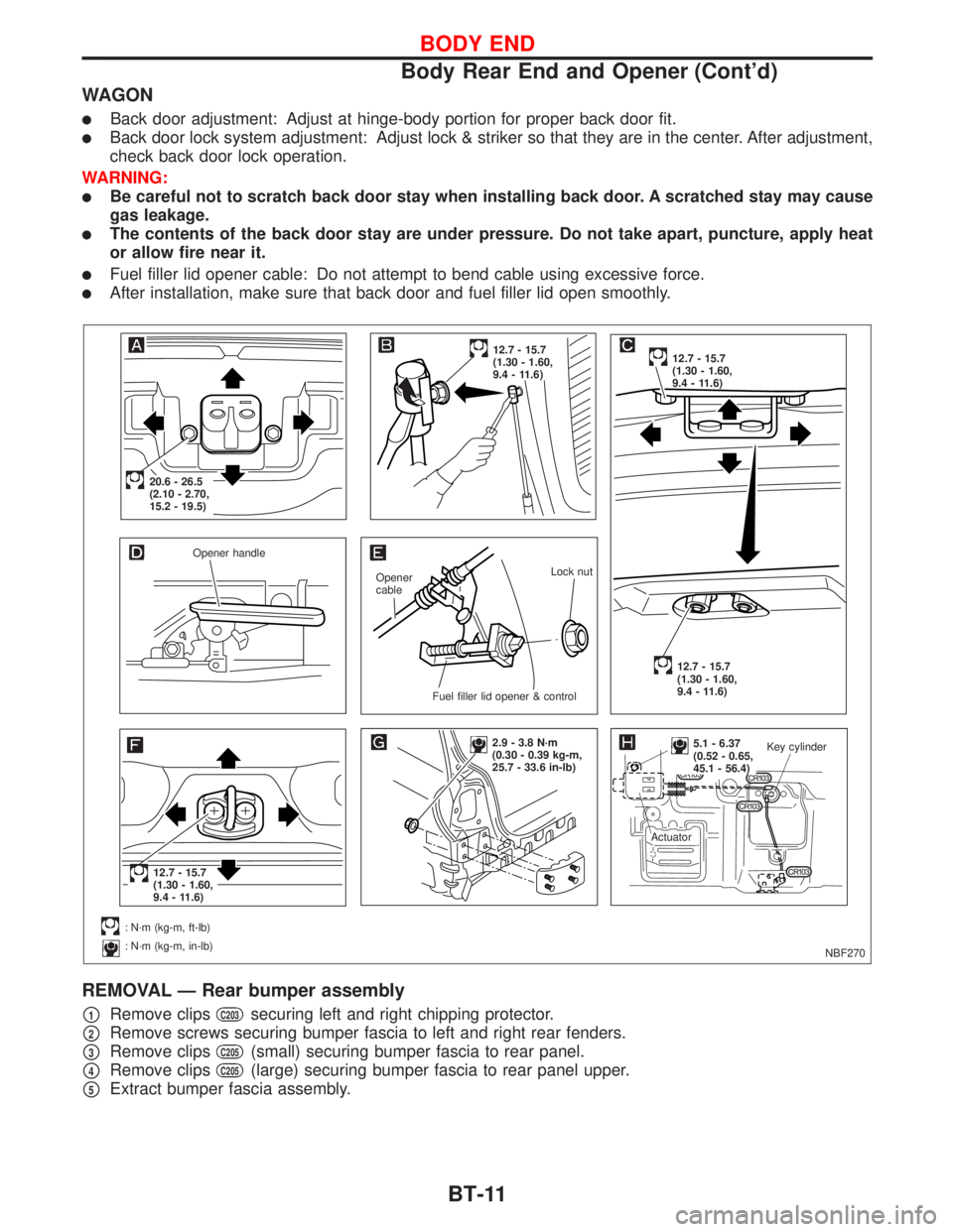
lBack door adjustment: Adjust at hinge-body portion for proper back door fit.
lBack door lock system adjustment: Adjust lock & striker so that they are in the center. After adjustment,
check back door lock operation.
WARNING:
lBe careful not to scratch back door stay when installing back door. A scratched stay may cause
gas leakage.
lThe contents of the back door stay are under pressure. Do not take apart, puncture, apply heat
or allow fire near it.
lFuel filler lid opener cable: Do not attempt to bend cable using excessive force.
lAfter installation, make sure that back door and fuel filler lid open smoothly.
REMOVAL Ð Rear bumper assembly
p1Remove clipsC203securing left and right chipping protector.
p2Remove screws securing bumper fascia to left and right rear fenders.
p3Remove clipsC205(small) securing bumper fascia to rear panel.
p4Remove clipsC205(large) securing bumper fascia to rear panel upper.
p5Extract bumper fascia assembly.
NBF270 Opener handle
Opener
cableLock nut
.Fuel filler lid opener & control
.20.6 - 26.5
(2.10 - 2.70,
15.2 - 19.5)
12.7 - 15.7
(1.30 - 1.60,
9.4 - 11.6)12.7 - 15.7
(1.30 - 1.60,
9.4 - 11.6)
12.7 - 15.7
(1.30 - 1.60,
9.4 - 11.6)
.12.7 - 15.7
(1.30 - 1.60,
9.4 - 11.6)
: N´m (kg-m, ft-lb)
: N´m (kg-m, in-lb)
2.9 - 3.8 N´m
(0.30 - 0.39 kg-m,
25.7 - 33.6 in-lb)..5.1 - 6.37
(0.52 - 0.65,
45.1 - 56.4)Key cylinder
Actuator
BODY END
Body Rear End and Opener (Cont'd)
BT-11
Page 308 of 2267
System Chart
Crankshaft position sensor
(TDC)E
ECM
Control sleeve position sensorE
Fuel temperature sensorE
Mass air flow sensorE
Engine coolant temperature
sensorE
Needle lift sensorE
Accelerator position sensorE
Accelerator position switchE
Air conditioner switchE
Ignition switch (ON & ST POS.)E
Battery voltageE
Vehicle speed sensor or ABS
actuator and electric unit (con-
trol unit)E
Brake switchE
Atmospheric pressure sensorE
EFuel injection controlEElectric governor
EFuel injection timing controlEInjection timing control
valve
EFuel cut controlEFuel cut solenoid valve
EGlow control systemEGlow relay & glow lamp
EOn board diagnostic systemEMalfunction indicator
(On the instrument panel)
EEGR valve controlEEGRC-solenoid valve A & B
ECooling fan controlECooling fan relays
EAir conditioning cut controlEAir conditioner relay
ECooling fan motor controlECooling fan relay
ENGINE AND EMISSION CONTROL OVERALL SYSTEMCD20T
EC-14
Page 311 of 2267
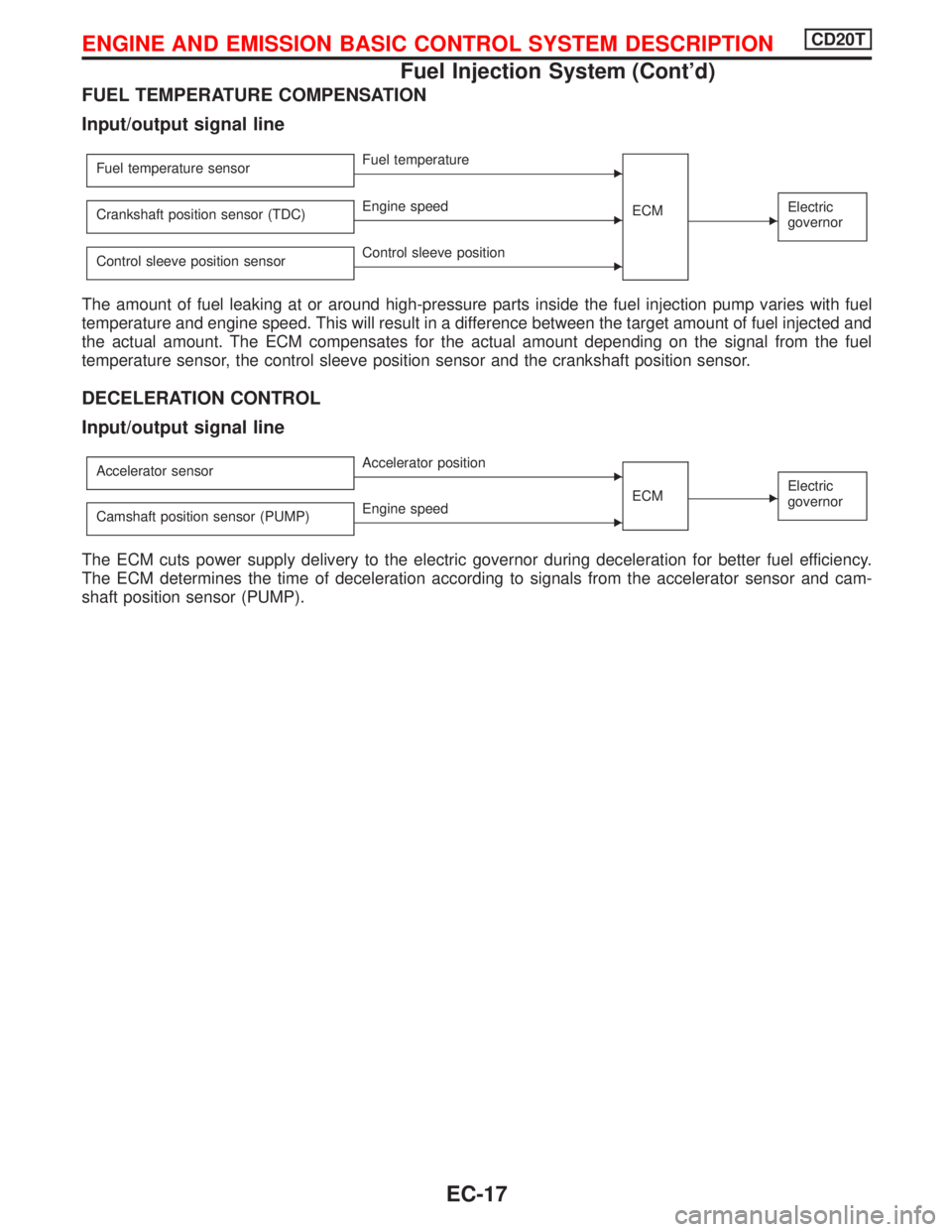
FUEL TEMPERATURE COMPENSATION
Input/output signal line
Fuel temperature sensorEFuel temperature
ECM
EElectric
governorCrankshaft position sensor (TDC)EEngine speed
Control sleeve position sensor
EControl sleeve position
The amount of fuel leaking at or around high-pressure parts inside the fuel injection pump varies with fuel
temperature and engine speed. This will result in a difference between the target amount of fuel injected and
the actual amount. The ECM compensates for the actual amount depending on the signal from the fuel
temperature sensor, the control sleeve position sensor and the crankshaft position sensor.
DECELERATION CONTROL
Input/output signal line
Accelerator sensorEAccelerator position
ECM
EElectric
governor
Camshaft position sensor (PUMP)EEngine speed
The ECM cuts power supply delivery to the electric governor during deceleration for better fuel efficiency.
The ECM determines the time of deceleration according to signals from the accelerator sensor and cam-
shaft position sensor (PUMP).
ENGINE AND EMISSION BASIC CONTROL SYSTEM DESCRIPTIONCD20T
Fuel Injection System (Cont'd)
EC-17
Page 312 of 2267
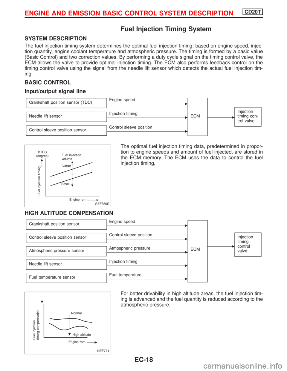
Fuel Injection Timing System
SYSTEM DESCRIPTION
The fuel injection timing system determines the optimal fuel injection timing, based on engine speed, injec-
tion quantity, engine coolant temperature and atmospheric pressure. The timing is formed by a basic value
(Basic Control) and two correction values. By performing a duty cycle signal on the timing control valve, the
ECM allows the valve to provide optimal injection timing. The ECM also performs feedback control on the
timing control valve using the signal from the needle lift sensor which detects the actual fuel injection tim-
ing.
BASIC CONTROL
Input/output signal line
Crankshaft position sensor (TDC)EEngine speed
ECM
E
Injection
timing con-
trol valveNeedle lift sensorEInjection timing
Control sleeve position sensor
EControl sleeve position
The optimal fuel injection timing data, predetermined in propor-
tion to engine speeds and amount of fuel injected, are stored in
the ECM memory. The ECM uses the data to control the fuel
injection timing.
HIGH ALTITUDE COMPENSATION
Crankshaft position sensorEEngine speed
ECM
E
Injection
timing
control
valveControl sleeve position sensorEControl sleeve position
Atmospheric pressure sensor
EAtmospheric pressure
Needle lift sensor
EInjection timing
Fuel temperature sensor
EFuel temperature
For better drivability in high altitude areas, the fuel injection tim-
ing is advanced and the fuel quantity is reduced according to the
atmospheric pressure.
SEF650S
Fuel injection timing
BTDC
(degree)Fuel injection
volume
Large
Small
Engine rpm
NEF771
Fuel injection
timing compensation
Normal
High altitude
Engine rpm
ENGINE AND EMISSION BASIC CONTROL SYSTEM DESCRIPTIONCD20T
EC-18
Page 316 of 2267
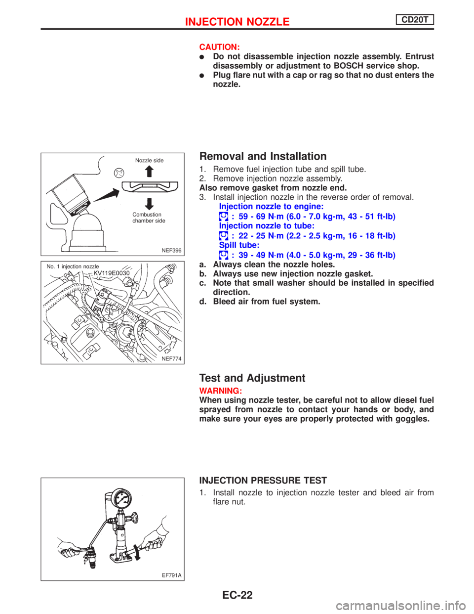
CAUTION:
lDo not disassemble injection nozzle assembly. Entrust
disassembly or adjustment to BOSCH service shop.
lPlug flare nut with a cap or rag so that no dust enters the
nozzle.
Removal and Installation
1. Remove fuel injection tube and spill tube.
2. Remove injection nozzle assembly.
Also remove gasket from nozzle end.
3. Install injection nozzle in the reverse order of removal.
Injection nozzle to engine:
: 59 - 69 N´m (6.0 - 7.0 kg-m, 43 - 51 ft-lb)
Injection nozzle to tube:
: 22 - 25 N´m (2.2 - 2.5 kg-m, 16 - 18 ft-lb)
Spill tube:
: 39 - 49 N´m (4.0 - 5.0 kg-m, 29 - 36 ft-lb)
a. Always clean the nozzle holes.
b. Always use new injection nozzle gasket.
c. Note that small washer should be installed in specified
direction.
d. Bleed air from fuel system.
Test and Adjustment
WARNING:
When using nozzle tester, be careful not to allow diesel fuel
sprayed from nozzle to contact your hands or body, and
make sure your eyes are properly protected with goggles.
INJECTION PRESSURE TEST
1. Install nozzle to injection nozzle tester and bleed air from
flare nut.
NEF396
Nozzle side
Combustion
chamber side
NEF774 No. 1 injection nozzle
EF791A
INJECTION NOZZLECD20T
EC-22
Page 341 of 2267
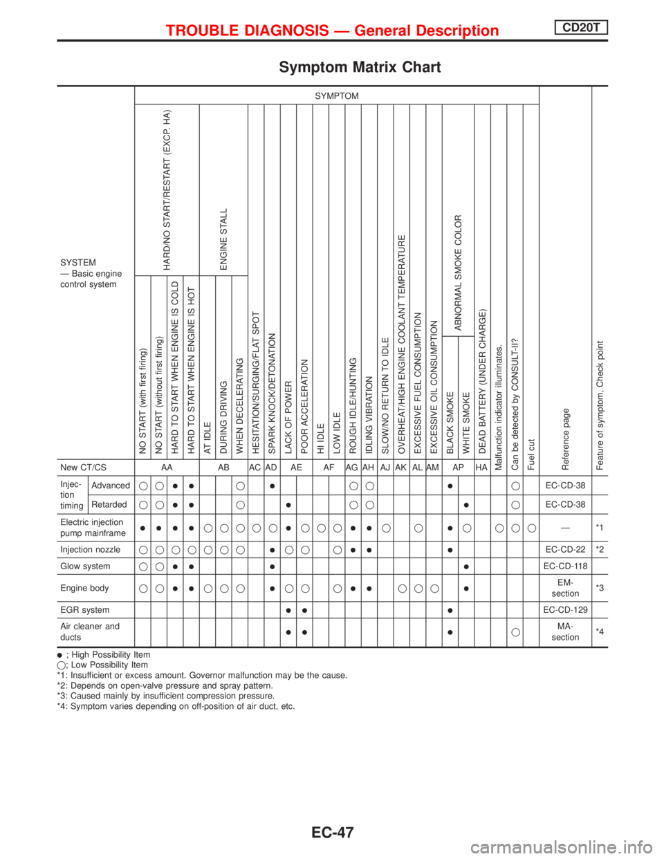
Symptom Matrix Chart
SYSTEM
Ð Basic engine
control systemSYMPTOM
Reference page
Feature of symptom, Check pointHARD/NO START/RESTART (EXCP. HA)
ENGINE STALL
HESITATION/SURGING/FLAT SPOT
SPARK KNOCK/DETONATION
LACK OF POWER
POOR ACCELERATION
HI IDLE
LOW IDLE
ROUGH IDLE/HUNTING
IDLING VIBRATION
SLOW/NO RETURN TO IDLE
OVERHEAT/HIGH ENGINE COOLANT TEMPERATURE
EXCESSIVE FUEL CONSUMPTION
EXCESSIVE OIL CONSUMPTION
ABNORMAL SMOKE COLOR
DEAD BATTERY (UNDER CHARGE)
Malfunction indicator illuminates.
Can be detected by CONSULT-II?
Fuel cutNO START (with first firing)
NO START (without first firing)
HARD TO START WHEN ENGINE IS COLD
HARD TO START WHEN ENGINE IS HOT
AT IDLE
DURING DRIVING
WHEN DECELERATING
BLACK SMOKE
WHITE SMOKENew CT/CS AA AB AC AD AE AF AG AH AJ AK AL AM AP HA
Injec-
tion
timingAdvancedqq
llqlqqlqEC-CD-38
Retardedqq
llqlqqlqEC-CD-38
Electric injection
pump mainframe
llllqqqqqlqqqllqqlq qqqÐ*1
Injection nozzleqqqqqqq
lqq qll lEC-CD-22 *2
Glow systemqq
ll l lEC-CD-118
Engine bodyqq
llqqqlqq qllqqqlEM-
section*3
EGR system
ll lEC-CD-129
Air cleaner and
ducts
ll lqMA-
section*4
l; High Possibility Item
q; Low Possibility Item
*1: Insufficient or excess amount. Governor malfunction may be the cause.
*2: Depends on open-valve pressure and spray pattern.
*3: Caused mainly by insufficient compression pressure.
*4: Symptom varies depending on off-position of air duct, etc.
TROUBLE DIAGNOSIS Ð General DescriptionCD20T
EC-47
Page 376 of 2267
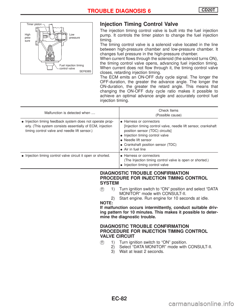
Injection Timing Control Valve
The injection timing control valve is built into the fuel injection
pump. It controls the timer piston to change the fuel injection
timing.
The timing control valve is a solenoid valve located in the line
between high-pressure chamber and low-pressure chamber. It
changes fuel pressure in the high-pressure chamber.
When current flows through the solenoid (the solenoid turns ON),
the timing control valve opens, advancing fuel injection timing.
When current does not flow through it, the timing control valve
closes, retarding injection timing.
The ECM emits an ON-OFF duty cycle signal. The longer the
OFF-duration, the greater the advance angle. The longer the
ON-duration, the greater the retard angle. This means that
changing the ON-OFF duty cycle ratio makes it possible to
achieve an optimal advance angle and accurately control fuel
injection timing.
Malfunction is detected when ....Check Items
(Possible cause)
lInjection timing feedback system does not operate prop-
erly. (This system consists essentially of ECM, injection
timing control valve and needle lift sensor.)lHarness or connectors
[Injection timing control valve, needle lift sensor, crankshaft
position sensor (TDC) circuits]
lInjection timing control valve
lNeedle lift sensor
lCrankshaft position sensor (TDC)
lAir in fuel line
lInjection timing control valve circuit it open or shorted.lHarness or connectors
(The Injection timing control valve is open or shorted.)
lInjection timing control valve
DIAGNOSTIC TROUBLE CONFIRMATION
PROCEDURE FOR INJECTION TIMING CONTROL
SYSTEM
1) Turn ignition switch to ªONº position and select ªDATA
MONITORº mode with CONSULT-II.
2) Start engine. Run engine for 10 seconds at idle.
NOTE:
If malfunction occurs intermittently, conduct suitable driv-
ing pattern for 10 minutes. This makes it possible to deter-
mine the diagnostic trouble.
DIAGNOSTIC TROUBLE CONFIRMATION
PROCEDURE FOR INJECTION TIMING CONTROL
VALVE CIRCUIT
1) Turn ignition switch to ªONº position.
2) Select ªDATA MONITORº mode with CONSULT-II.
3) Wait at least 2 seconds.
SEF638S Timer piston
High
pres-
sureLow
pressure
Fuel injection timing
control valve
TROUBLE DIAGNOSIS 6CD20T
EC-82
Page 441 of 2267
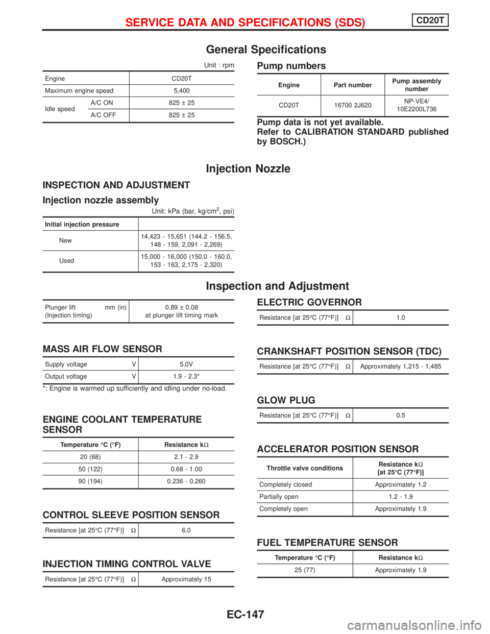
General Specifications
Unit : rpm
Engine CD20T
Maximum engine speed 5,400
Idle speedA/C ON 825 25
A/C OFF 825 25
Pump numbers
Engine Part numberPump assembly
number
CD20T 16700 2J620NP-VE4/
10E2200L736
Pump data is not yet available.
Refer to CALIBRATION STANDARD published
by BOSCH.)
Injection Nozzle
INSPECTION AND ADJUSTMENT
Injection nozzle assembly
Unit: kPa (bar, kg/cm2, psi)
Initial injection pressure
New14,423 - 15,651 (144.2 - 156.5,
148 - 159, 2,091 - 2,269)
Used15,000 - 16,000 (150.0 - 160.0,
153 - 163, 2,175 - 2,320)
Inspection and Adjustment
Plunger lift mm (in)
(Injection timing)0.89 0.08
at plunger lift timing mark
MASS AIR FLOW SENSOR
Supply voltage V 5.0V
Output voltage V 1.9 - 2.3*
*: Engine is warmed up sufficiently and idling under no-load.
ENGINE COOLANT TEMPERATURE
SENSOR
Temperature ÉC (ÉF) Resistance kW
20 (68) 2.1 - 2.9
50 (122) 0.68 - 1.00
90 (194) 0.236 - 0.260
CONTROL SLEEVE POSITION SENSOR
Resistance [at 25ÉC (77ÉF)]W6.0
INJECTION TIMING CONTROL VALVE
Resistance [at 25ÉC (77ÉF)]WApproximately 15
ELECTRIC GOVERNOR
Resistance [at 25ÉC (77ÉF)]W1.0
CRANKSHAFT POSITION SENSOR (TDC)
Resistance [at 25ÉC (77ÉF)]WApproximately 1,215 - 1,485
GLOW PLUG
Resistance [at 25ÉC (77ÉF)]W0.5
ACCELERATOR POSITION SENSOR
Throttle valve conditionsResistance kW
[at 25ÉC (77ÉF)]
Completely closed Approximately 1.2
Partially open 1.2 - 1.9
Completely open Approximately 1.9
FUEL TEMPERATURE SENSOR
Temperature ÉC (ÉF) Resistance kW
25 (77) Approximately 1.9
SERVICE DATA AND SPECIFICATIONS (SDS)CD20T
EC-147