low oil pressure NISSAN PULSAR 1987 Owner's Manual
[x] Cancel search | Manufacturer: NISSAN, Model Year: 1987, Model line: PULSAR, Model: NISSAN PULSAR 1987Pages: 238, PDF Size: 28.91 MB
Page 70 of 238
70 Cooling and Heating Systems
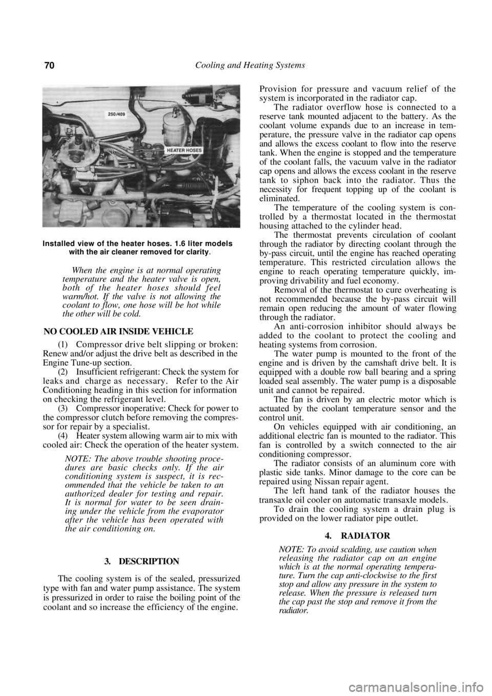
Installed view of the heater hoses. 1.6 liter models with the air cleaner removed for clarity
.
When the engine is at normal operating
temperature and the heater valve is open,
both of the heater hoses should feel
warm/hot. If the valve is not allowing the
coolant to flow, one hose will be hot while
the other will be cold.
NO COOLED AIR INSIDE VEHICLE
(1) Compressor drive belt slipping or broken:
Renew and/or adjust the drive belt as described in the
Engine Tune-up section.
(2) Insufficient refrigerant: Check the system for
leaks and charge as necessary. Refer to the Air
Conditioning heading in th is section for information
on checking the refrigerant level. (3) Compressor inoperative: Check for power to
the compressor clutch before removing the compres-
sor for repair by a specialist. (4) Heater system allowing warm air to mix with
cooled air: Check the operation of the heater system.
NOTE: The above trouble shooting proce-
dures are basic checks only. If the air
conditioning system is suspect, it is rec-
ommended that the vehicle be taken to an
authorized dealer for testing and repair.
It is normal for water to be seen drain-
ing under the vehicle from the evaporator
after the vehicle has been operated with
the air conditioning on.
3. DESCRIPTION
The cooling system is of the sealed, pressurized
type with fan and water pump assistance. The system
is pressurized in order to raise the boiling point of the
coolant and so increase the efficiency of the engine.
Provision for pressure a nd vacuum relief of the
system is incorporated in the radiator cap.
The radiator overflow hose is connected to a
reserve tank mounted adjacent to the battery. As the
coolant volume expands due to an increase in tem-
perature, the pressure valve in the radiator cap opens
and allows the excess coolant to flow into the reserve
tank. When the engine is stopped and the temperature
of the coolant falls, the vacuum valve in the radiator
cap opens and allows the excess coolant in the reserve
tank to siphon back into the radiator. Thus the
necessity for frequent topping up of the coolant is
eliminated.
The temperature of the cooling system is con-
trolled by a thermostat located in the thermostat
housing attached to the cylinder head.
The thermostat prevents circulation of coolant
through the radiator by directing coolant through the
by-pass circuit, until the engine has reached operating
temperature. This restricted circulation allows the
engine to reach operating temperature quickly, im-
proving drivability and fuel economy.
Removal of the thermostat to cure overheating is
not recommended because th e by-pass circuit will
remain open reducing the amount of water flowing
through the radiator.
An anti-corrosion inhibitor should always be
added to the coolant to protect the cooling and
heating systems from corrosion.
The water pump is mounted to the front of the
engine and is driven by the camshaft drive belt. It is
equipped with a double row ball bearing and a spring
loaded seal assembly. The water pump is a disposable
unit and cannot be repaired.
The fan is driven by an electric motor which is
actuated by the coolant temperature sensor and the
control unit.
On vehicles equipped with air conditioning, an
additional electric fan is m ounted to the radiator. This
fan is controlled by a sw itch connected to the air
conditioning compressor.
The radiator consists of an aluminum core with
plastic side tanks. Minor damage to the core can be
repaired using Nissan repair agent.
The left hand tank of the radiator houses the
transaxle oil cooler on automatic transaxle models.
To drain the cooling system a drain plug is
provided on the lower radiator pipe outlet.
4. RADIATOR
NOTE: To avoid scalding, use caution when
releasing the radiator cap on an engine
which is at the normal operating tempera-
ture. Turn the cap anti-clockwise to the first
stop and allow any pressure in the system to
release. When the pressure is released turn
the cap past the stop and remove it from the
radiator.
Page 72 of 238
72 Cooling and Heating Systems
(16) After the vehicle has been driven several
kilometers check the coolant level in the reserve tank
and top up if necessary.
TO REMOVE
(1) Drain the cooling system as previously de-
scribed.
(2) Loosen the hose clamps and disconnect the
hoses from the radiator. (3) If applicable disconnect the automatic trans-
axle oil cooler hoses from the left hand side radiator
tank. Plug the hoses and fitt ings to prevent the entry
of dirt and the loss of fluid.
(4) Disconnect the hose from the reserve tank at
the top of the radiator. (5) On models with air conditioning, remove the
hoses and support bracket bolts and move the bracket
and hoses away from the top of the radiator. (6) Remove the radiator support bracket bolts
from the radiator support pa nel and lift the radiator
from the lower mountings and out of the vehicle.
NOTE: A radiator that has been in use for
some time should not be allowed to stand
empty for any length of time. The radiator
should be immersed in a tank of coolant or
otherwise kept full. If applicable, ensure that
no coolant is allowed to enter the automatic
transaxle oil cooler in the left hand side tank
of the radiator.
Failure to observe this precaution may
result in overheating when the engine is put
back into service. This is caused by internal
deposits in the radiator drying and flaking
and so obstructing the circulation of the
coolant in the system.
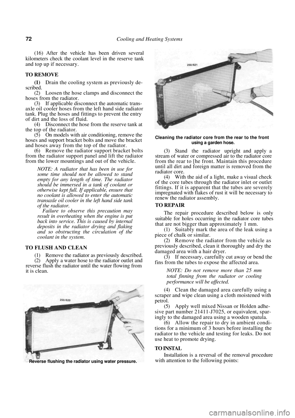
TO FLUSH AND CLEAN
(1) Remove the radiator as previously described.
(2) Apply a water hose to the radiator outlet and
reverse flush the radiator until the water flowing from
it is clean.
Cleaning the radiator core from the rear to the front
using a garden hose.
(3) Stand the radiator upright and apply a
stream of water or compressed air to the radiator core
from the rear to [he front. Maintain this procedure
until all dirt and foreign matter is removed from the
radiator core.
(4) With the aid of a light, make a visual check
of the core tubes through the radiator inlet or outlet
fittings. If it is apparent that the tubes are severely
impregnated with flakes of rust it will be necessary to
renew the radiator assembly.
TO REPAIR
The repair procedure described below is only
suitable for holes occurring in the radiator core tubes
that are not bigger than approximately 1 mm.
(1) Suitably mark the area of the leak using a
piece of chalk or similar. (2) Remove the radiator from the vehicle as
previously described, clean it thoroughly and dry the
damaged area with a hair dryer. (3) If necessary, carefully cut away or bend the
fins from the tubes to expose the affected area.
NOTE: Do not remove more than 25 mm
total finning from the radiator or cooling
performance will be affected.
(4) Clean the damaged area carefully using a
scraper and wipe clean using a cloth moistened with
petrol.
(5) Apply well mixed Nissan or Holden adhe-
sive part number 21411-J7025, or equivalent, spar-
ingly to the damaged area using a wooden spatula.
(6) Allow the repair to dry in ambient condi-
tions for a minimum of 3 hours before installing the
radiator to the vehicle and testing for leaks. Do not
use heat to promote drying.
TO INSTAL
Installation is a reversal of the removal procedure
with attention to the following points:
Reverse flushing the radiator using water pressure.
Page 80 of 238
Cooling and Heating Systems
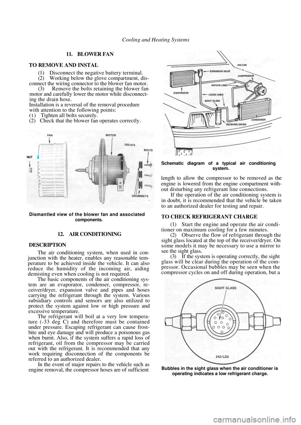
11. BLOWER FAN
TO REMOVE AND INSTAL
(1) Disconnect the negative battery terminal.
(2) Working below the glov e compartment, dis-
connect the wiring connector to the blower fan motor.
(3) Remove the bolts retaining the blower fan
motor and carefully lower the motor while disconnect-
ing the drain hose.
Installation is a reversal of the removal procedure
with attention to the following points:
( t ) Tighten all bolts securely.
(2) Check that the blow er fan operates correctly.
Dismantled view of the blower fan and associated
components.
12. AIR CONDITIONING
DESCRIPTION
The air conditioning system, when used in con-
junction with the heater, enables any reasonable tem-
perature to be achieved inside the vehicle. It can also
reduce the humidity of the incoming air, aiding
demisting even when cooling is not required.
The basic components of the air conditioning sys-
tem are an evaporator, co ndenser, compressor, re-
ceiver/dryer, expansion valve and pipes and hoses
carrying the refrigerant through the system. Various
subsidiary controls and sensors are also utilized to
protect the system against low or high pressure and
excessive temperature.
The refrigerant will boil at a very low tempera-
ture (-33 deg C) and therefore must be contained
under pressure. Escaping refrigerant can cause frost-
bite and eye damage and will produce a poisonous gas
when burnt. Also, if the system suffers a rapid loss of
refrigerant, oil from the compressor may be carried
out with the refrigerant. It is recommended that any
work requiring disconnection of the components be
referred to an au thorized dealer.
In the event of major repair s to the vehicle such as
engine removal, the compress or hoses are of sufficient
Schematic diagram of a typical air conditioning
system.
length to allow the compressor to be removed as the
engine is lowered from the engine compartment with-
out disturbing any refrigerant line connections.
If the operation of the air conditioning system is
in doubt, it is recommended that the vehicle be taken
to an authorized dealer for testing and repair.
TO CHECK REFRIGERANT CHARGE
(1) Start the engine and operate the air condi-
tioner on maximum cooling for a few minutes.
(2) Observe the flow of refrigerant through the
sight glass located at the top of the receiver/dryer. On
some models it may be necessary to use a mirror to
see the sight glass. (3) If the system is operating correctly, the sight
glass will be clear during the operation of the com-
pressor. Occasional bubbles may be seen when the
compressor cycles on and off during operation, but a
NUT j-
Bubbles in the sight glass when the air conditioner is
operating indicates a low refrigerant charge.
Page 82 of 238

82
FUEL AND ENGINE MANAGEMENT
CAUTION: To prevent severe electrical shock, extreme care must be taken when
working on or near the electronic ignition system as dangerous high tension voltages
are produced in both the primary and secondary circuits. See the text fo\
r
precautionary notes.
SPECIFICATIONS
FUEL INJECTION
Type:
1.6 liter engine .................................. Single point
1.8 liter engine................................... Multi point
FUEL PUMP
Type ................................................................ Electric
Pressure at idle:
1.6 liter engine ..................................... 62-90 kPa
1.8 liter engine ................................ 190-230 kPa
FUEL FILTER
Type ................................................ Inline, disposable
AIR FILTER
Type ................................... Disposable paper element
DISTRIBUTOR
Make ........................................................ Delco Remy
Advance contro l .......................................... Electronic
Rotation of rotor .................................. Anti-clockwise
Firing order....................................................1 -3-4-2
ADJUSTMENTS
Base idle speed ..................................... 550-650 rpm
Ignition timing.......................................... 10° BTDC
TORQUE WRENCH SETTINGS
Throttle body nuts.......................................... 10 Nm
*Throttle body bolts ........................................ 12 Nm
*Fuel hose fittings............................................ 35 Nm
Fuel rail bolts ....................................................8 Nm
Fuel tank drain plug ........................................ 24 Nm
Coolant temperature sensor ............................ 12 Nm
Oxygen sensor .................................................. 40 Nm
MAT sensor..................................................... 14 Nm
*1.6 liter engine
l . 8 liter engine
1. FUEL AND ENGINE MANAGEMENT
TROUBLE SHOOTING
NOTE: The following Trouble Shooting pro-
cedures are basic checks only. If these pro-
cedures fail to locate the fault, refer to the
System Diagnosis and Adjustments heading
for more thorough testing.
Prior to performing any of the following
operations, refer to the Service Precautions
and Procedures heading.
ENGINE WILL NOT START OR HARD TO
START
(1) Water in the fuel: Dr ain the fuel from the
system and renew the fuel filter.
(2) Fault in the power supply: Check the battery,
fusible links and fuses. Check for clean, secure con-
nections, particularly the earth connections. Check the
EG1 and fuel pump relays.
NOTE: If the fuel pump relay fails, power
will be supplied to the fuel pump via the oil
pressure switch. When starting the engine,
Check that the MAP sensor hose is not blocked or split
and ensure that all electrical connections are clean and
secure.
Page 83 of 238

Fuel and Engine Management 83
the fuel pump will not operate until the oil
pressure is sufficient to extinguish the oil
pressure warning lamp. Therefore it will be
necessary to operate the starter motor for a
longer period than usual to start the engine.
(3) Faulty EFI component wiring connections:
Check that all component wiring connections are
clean and secure.
(4) Manifold absolute pressure (MAP) sensor
vacuum hose blocked or disconnected: Clear or recon-
nect the vacuum hose. (5) Fault in the ignition system: Check the
primary and secondary ignition circuits.
(6) Engine flooded: Fully depress the throttle
pedal until the engine starts. Check the coolant
temperature sensor. Check th e injector(s) for leakage.
ENGINE STARTS THEN STALLS
(1) Water in the fuel: Dr ain the fuel from the
system and renew the fuel filter.
(2) Air leakage at the inlet manifold: Check all
joints and hoses for air leaks. (3) Faulty EFI wiring connections: Check that
all component wiring connections are clean and
secure.
(4) Ignition timing incorrectly set: Check and
adjust the timing. (5) MAP sensor faulty or supply hose discon-
nected or blocked: Check the vacuum supply hose.
Check the operation of the MAP sensor.
ENGINE MISFIRES
(1) Faulty, dirty or incorrectly adjusted spark
plugs: Renew or clean and adjust the spark plugs.
(2) Condensation in the distributor cap: Dry and
examine the cap for cracks. (3) Faulty high tension leads: Check and renew
the high tension leads.
Testing the fuel system pressure using a pressure
gauge.
(4) Faulty ignition coil: Check and renew the
ignition coil.
(5) Fuel blockage: Check for blockage in the fuel
filter, lines and injector(s). (6) Low fuel pressure: Check the fuel pump and
fuel pressure regulator. (7) Water in the fuel: Dr ain the fuel from the
system and renew the fuel filter. (8) Loose fuel supply wiring connectors: Check
all connectors for tightness. (9) Faulty fuel injector: Check the connections
and test the condition of the fuel injectors.
ENGINE LACKS POWER
(1) Ignition timing incorrectly set: Check and
adjust the timing.
(2) Water in the fuel: Dr ain the fuel from the
system and renew the fuel filter.
(3) Incorrectly adjusted throttle cable: Adjust the
throttle cable.
Check the distributor cap for cracks or tracking be- tween the terminals. The air filter element should be renewed at 40 000 km
intervals. 1.8 liter engine.
Page 85 of 238

Fuel and Engine Management 85
View of the 1.6 liter engine showing the engine management components. Air cleaner removed for clarity.
series of tests on various components in the system
and records the results, If a fault is discovered, the
ECM warning lamp on the instrument cluster will
illuminate while the engine is running. When the self
diagnosis mode is activated, the ECM warning lamp
will flash codes indicating the area in which the fault
has occurred.
This function is very useful in locating system
faults, particularly intermittent problems. However,
the self diagnosis mode does not provide comprehen-
sive testing of the EFI system, and therefore should
always be used in conjunction with the other test
procedures described later in this section in order to
accurately locate system faults.
The high energy electronic ignition system con-
sists of a distributor and an ignition coil.
The distributor has two functions. The first is to
produce and distribute secondary high tension voltage
to the spark plugs.
The second function is to provide the control unit
with information on engine speed and crankshaft
position.
The ignition timing is constantly adjusted by the
control unit to suit varying engine and vehicle oper-
ating conditions.
In the fuel injection system, a metered amount of
fuel is sprayed into the air stream. The air/fuel
mixture then enters the combustion chamber via the
inlet valves.
On 1.6 liter engines, the fuel is injected by a single
injector, located above the throttle valve within the
throttle body assembly. The injector fires twice per
engine revolution under most operating conditions.
On 1.8 liter engines, four injectors are used. The
fuel is distributed to the injectors via the fuel rail. All
injectors fire simultaneous ly once per engine revolu-
tion under most operating conditions.
Under conditions of high load the control unit
may signal the injector(s) to fire more often. However,
if the engine speed exceeds 6 700 rpm the control unit
will cease firing the injectors until the engine speed is
below 6 200 rpm.
Fuel is supplied under pressu re by an electric fuel
pump mounted in the fuel tank and the pressure is
regulated by a pressure regulator.
On 1.6 liter engines, the regulator consists of a
spring tensioned diaphragm which is mounted to the
side of the throttle body assembly. The fuel pressure is
regulated by the tension of the spring against the
diaphragm, opening and closing the fuel return port.
On 1.8 liter engines, the pressure regulator is
mounted adjacent to the fuel rail and consists of a
diaphragm with fuel pressu re acting on one side and
spring tension and manifold vacuum acting on the
Page 102 of 238
\(V2 Fuel and Engine Management
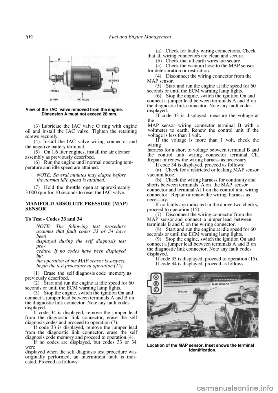
View of the IAC valve removed from the engine. Dimension A must not exceed 28 mm.
(3) Lubricate the IAC valve O ring with engine
oil and install the IAC valve. Tighten the retaining
screws securely.
(4). Install the IAC valve wiring connector and
the negative battery terminal.
(5) On 1.6 liter engines, install the air cleaner
assembly as previously described. (6) Run the engine until normal operating tem-
perature and idle speed are attained.
NOTE: Several minutes may elapse before
the normal idle speed is attained.
(7) Hold the throttle open at approximately
3 000 rpm for 10 seconds to reset the IAC valve.
MANIFOLD ABSOLUTE PRESSURE (MAP)
SENSOR
To Test - Codes 33 and 34
NOTE: The following test procedure
assumes that fault codes 33 or 34 have
been
displayed during the self diagnosis test
pro-
cedure. If no codes have been displayed
but
the operation of the MAP sensor is suspect,
begin the test procedure at operation (15).
(1) Erase the self diagnosis code memory as
previously described.
(2) Start and run the engine at idle speed for 60
seconds or until the ECM warning lamp lights.
(3) Stop the engine, switch the ignition On and
connect a jumper lead between terminals A and B on
the diagnostic link connector. Note any fault codes
displayed. If code 34 is displayed, remove the jumper lead
from the diagnostic link connector, erase the self
diagnosis codes and proceed to operation (7).
If code 33 is displayed, remove the jumper lead
from the diagnostic link connector, erase the self
diagnosis code memory and proceed to operation (4).
If no codes are displayed, but codes 33 or 34
were
displayed when the self diagnosis test procedure was
originally performed, an intermittent fault is indi-
cated. Proceed as follows:
(a) Check for faulty wiring connections. Check
that all wiring connectors are clean and secure. (b) Check that all earth wires are secure.
(c) Check the vacuum hose to the MAP sensor
for deterioration or restriction.
(4) Disconnect the wiring connector from the
MAP sensor. (5) Start and run the engine at idle speed for 60
seconds or until the ECM warning lamp lights. (6) Stop the engine, switch the ignition On and
connect a jumper lead between terminals A and B on
the diagnostic link connector. Note any fault codes
displayed.
If code 33 is displayed, measure the voltage at
the
MAP sensor wiring connector terminal B with a
voltmeter to earth. Renew the control unit if the
voltage is less than 1 volt.
If the voltage is more than 1 volt, check the
wiring
harness for a short to voltage between terminal B and
the control unit wiring connector terminal Cll.
Repair or renew the wiring harness as necessary.
If code 34 is displayed, proceed as follows:
(a) Check for a restricted or leaking MAP sensor
vacuum hose.
(b) Check the wiring harness for continuity and
shorts between terminals A on the MAP sensor
connector and terminal A11 on the control unit wiring
connector. Repair or renew the wiring harness as
necessary.
If no faults are indicated in the above two checks,
proceed to operation (15).
(7) Disconnect the wiring connector from the
MAP sensor and connect a jumper lead between
terminals B and C on the wiring connector. (8) Start and run the engine at idle speed for 60
seconds or until the ECM warning lamp lights. (9) Stop the engine, switch the ignition On and
connect a jumper lead between terminals A and B on
the diagnostic link connector. Note any fault codes
displayed.
If code 33 is displayed, proceed to operation (15).
If code 34 is displayed, proceed as follows.
Location of the MAP sensor. Inset shows the terminal
identification.
Page 121 of 238
121
CLUTCH
SPECIFICATIONS
Type................................................... Single dry plate
Operation................................................... Mechanical
Pressure plate type .................................... Diaphragm
Release bearing type .......................Prelubri cated ball
Driven plate:
Outside diameter .................................... 215 mm
Rivet depth limit ....................................0.3 mm
Runout limit .........................................0.5 mm
Maximum spline backlash ...................0.7 mm
Pressure plate:
Diaphragm spring height
(installed) ...................................... 30.5-32.5 mm
Spring finger vari ation limit.....................0.5 mm
Clutch pedal:
Height .............................................. 175-185 mm
Free play ....................................... 12.5-17.5 mm
Release lever free play............................ 2.5-3.5 mm
Flywheel machining limit ...............................0.3 mm
TORQUE WRENCH SETTINGS
Pressure plate bolts.......................................... 29 Nm
Pedal pivot pin nut ......................................... 22 Nm
Cable loc knut.................................................... 4 Nm
Lower clutch housing to engine bolts.............. 21 Nm
Centre and upper clutch housing
to engine bolts .................................................. 49 Nm
1. CLUTCH TROUBLE SHOOTING
CLUTCH SLIPPING
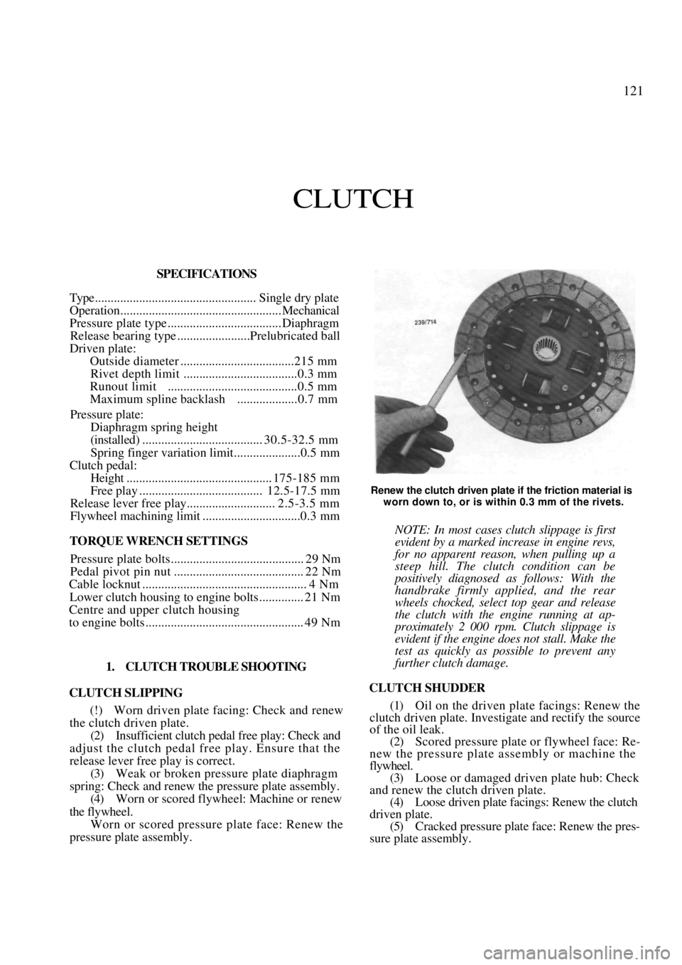
(!) Worn driven plate facing: Check and renew
the clutch driven plate.
(2) Insufficient clutch pedal free play: Check and
adjust the clutch pedal free play. Ensure that the
release lever free play is correct.
(3) Weak or broken pressure plate diaphragm
spring: Check and renew the pressure plate assembly. (4) Worn or scored flywh eel: Machine or renew
the flywheel. Worn or scored pressure plate face: Renew the
pressure plate assembly.
Renew the clutch driven plate if the friction material is
worn down to, or is within 0.3 mm of the rivets.
NOTE: In most cases clutch slippage is first
evident by a marked increase in engine revs,
for no apparent reason, when pulling up a
steep hill. The clutch condition can be
positively diagnosed as follows: With the
handbrake firmly applied, and the rear
wheels chocked, select top gear and release
the clutch with the engine running at ap-
proximately 2 000 rpm. Clutch slippage is
evident if the engine does not stall. Make the
test as quickly as possible to prevent any
further clutch damage.
CLUTCH SHUDDER
(1) Oil on the driven plate facings: Renew the
clutch driven plate. Invest igate and rectify the source
of the oil leak.
(2) Scored pressure plate or flywheel face: Re-
new the pressure plate assembly or machine the
flywheel. (3) Loose or damaged driven plate hub: Check
and renew the clutch driven plate. (4) Loose driven plate facings: Renew the clutch
driven plate. (5) Cracked pressure plate face: Renew the pres-
sure plate assembly.
Page 156 of 238

156
FRONT SUSPENSION
SPECIFICATIONS
Type.................. Independent MacPherson strut with
coil springs and control arms
Shock absorber .................. Hydraulic, non-repairable
Hub bearing end float (maximum) ............. 0.05 mm
Ball joint axial play (maximum) ....................0.7 mm
Ball joint turning torque (used)...............0.5-4.9 Nm
Wheel alignment:
Toe in ..................................................... 0-2 mm
Camber ........................................- 0 ° 1 0 ' ± 4 5 '
Caster ..............................................1 ° 1 0 ' ± 4 5 '
King pin inclination..................... 1 3 ° 5 5 ' ± 4 5 '
TORQUE WRENCH SETTINGS
Hub bearing nut..................................... 196-235 Nm
Suspension unit to steering knuckle nut ...... 118 Nm
Suspension unit to body nuts ......................... 29 Nm
Piston rod nut .................................................. 72 Nm
Brake caliper to steering knuckle bolts ........... 52 Nm
Ball joint to steering knuckle bolt ................... 86 Nm
Control arm bracket bolts ............................... 98 Nm
Control arm pivot bolt ................................ 118 Nm
Stabiliser bar link nuts..................................... 44 Nm
Stabiliser bar bracket bolts .............................. 21 Nm
1. FRONT SUSPENSION TROUBLE
SHOOTING
FRONT END NOISE
(1) Loose upper suspension mounting or piston
rod: Tighten the mounting or piston rod nuts. (2) Loose or worn suspension unit lower ball
joint: Tighten or renew the lower ball joint.
(3) Noise in the suspension unit: Renew the
faulty suspension unit, preferably in pairs.
(4) Worn or loose steering gear: Overhaul the
steering gear assembly. (5) Worn front hub bearings: Renew the hub
bearings:
(6) Loose or defective stab ilizer bar, control arm
or mountings: Check, tighten or renew the mounting
rubbers.
Check the ball joints for wear and deterioration.
(7) Worn stabilizer bar link ball joints: Renew
the stabilizer bar links.
(8) Drive shafts worn or insufficiently lubri-
cated: Check the lubricant and the dust boots and
renew as necessary. (9) Drive shaft splines in the hub or the
differential worn or dama ged: Check and renew as
necessary.
NOTE: To check the front suspension com-
ponents for wear, raise the front of the
vehicle, support it on chassis stands and
allow both front wheel to hang free. With an
assistant pushing and pulling the front
wheels in and out at the top and then at the
bottom, check for excessive looseness at the
front hub bearings and lower control arm
inner pivot bushes. Noise or vibration in the
front end can also be caused by excessive
tire or wheel unbalance. Drive shaft joint
noise is usually more pronounced when
moving slowly with the steering on full lock.
POOR OR ERRATIC ROAD HOLDING
ABILITY
(1) Low or uneven tire pressures: Inflate the
tires to the recommended pressures.
(2) Defective suspension unit: Renew the faulty
unit, preferably in pairs.
Page 164 of 238
164
REAR SUSPENSION
SPECIFICATIONS
Type........................... Independent MacPherson strut
Shock absorber.................... Oil filled, non-repairable
Maximum hub bearing end float ................. 0.05 mm
Rear wheel alignment:
Toe out ........................................3 mm ± 2 mm
Camber ............................................. - 1 ° ± 4 5 '
TORQUE WRENCH SETTINGS
Hub retaining nut ......................................... 255 Nm
Suspension unit retaining nuts ....................... 29 Nm
Upper mounting retaining nut ........................ 72 Nm
Suspension unit to knuckle nuts .................. 118 Nm
Control arms to knuckle nut ........................ 118 Nm
Control arms to crossmember nut ............... 118 Nm
Stabiliser bar mounting bracket bolts .......... 108 Nm
Stabiliser bar retaining nut.............................. 83 Nm
Backing plate bolts........................................... 45 Nm
1. REAR SUSPENSION TROUBLE SHOOTING
REAR END NOISE
( 1 ) Defective suspension unit or mounting: Re-
new the faulty components.
(2) Loose or worn control arm bushes or pivot
bolts: Check and tighten or renew the worn compo-
nents. (3) Broken coil spring: Renew the coil spring,
preferably in matching pairs. (4) Worn rear hub bearing: Check and renew the
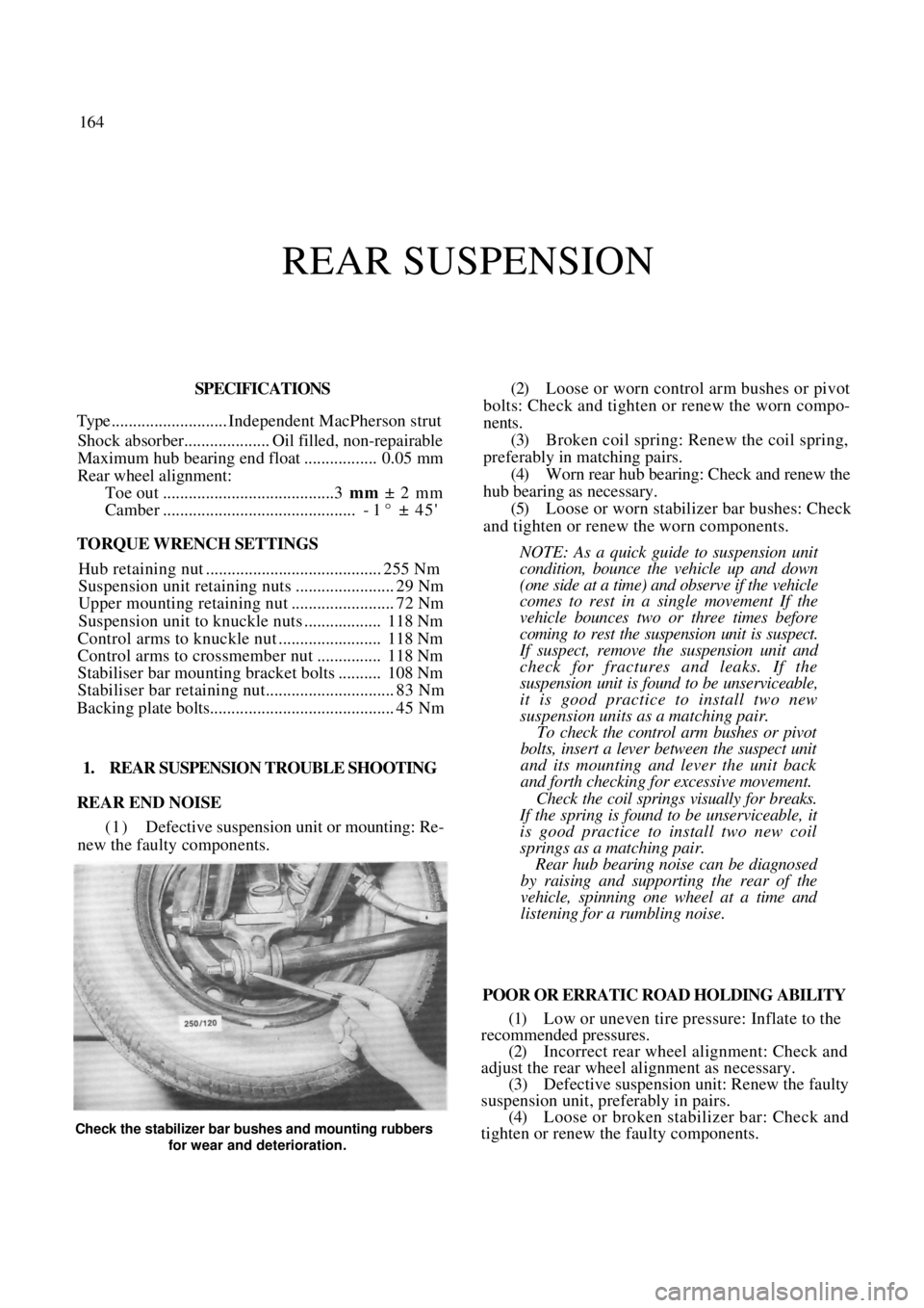
hub bearing as necessary. (5) Loose or worn stabilizer bar bushes: Check
and tighten or renew the worn components.
NOTE: As a quick guide to suspension unit
condition, bounce the vehicle up and down
(one side at a time) and observe if the vehicle
comes to rest in a single movement If the
vehicle bounces two or three times before
coming to rest the susp ension unit is suspect.
If suspect, remove the suspension unit and
check for fractures and leaks. If the
suspension unit is found to be unserviceable,
it is good practice to install two new
suspension units as a matching pair.
To check the control arm bushes or pivot
bolts, insert a lever between the suspect unit
and its mounting and lever the unit back
and forth checking for excessive movement.
Check the coil springs visually for breaks.
If the spring is found to be unserviceable, it
is good practice to install two new coil
springs as a matching pair.
Rear hub bearing noise can be diagnosed
by raising and supporting the rear of the
vehicle, spinning one wheel at a time and
listening for a rumbling noise.
POOR OR ERRATIC ROAD HOLDING ABILITY
(1) Low or uneven tire pressure: Inflate to the
recommended pressures.
(2) Incorrect rear wheel alignment: Check and
adjust the rear wheel alignment as necessary.
(3) Defective suspension unit: Renew the faulty
suspension unit, preferably in pairs. (4) Loose or broken stabilizer bar: Check and
tighten or renew the faulty components.
Check the stabilizer bar bushes and mounting rubbers
for wear and deterioration.