display NISSAN PULSAR 1987 Workshop Manual
[x] Cancel search | Manufacturer: NISSAN, Model Year: 1987, Model line: PULSAR, Model: NISSAN PULSAR 1987Pages: 238, PDF Size: 28.91 MB
Page 11 of 238
General Information 11
Lifting Equipment
When using lifting equipment to lift heavy com-
ponents such as the engine and/or transmission, use
metal slings or chain in preference to rope. If rope
must be used, ensure that it is not placed against sharp
edges on the component.
Automotive Lubricants and Solvents
Avoid prolonged skin contact with oils, greases
and solvents as some can cause skin irritations and
dermatitis.
Exercise caution when us ing cleaning solvents as
many are inflammable. Do not smoke. Keep naked
flames and sparks clear of the work area.
Compressed Air
Never point an air hose at another person or allow
compressed air to blow onto your skin. High pressure
air forced against the skin can enter the bloodstream
and prove fatal.
Suspension and Steering Components
Damaged suspension and steering components
should not be welded. Many of these components are
fabricated from toughened metals. If welded they may
lose their strength or become brittle. Damaged com-
ponents should be renewed.
Air Conditioning
Avoid disconnecting air conditioning hoses as
escaping refrigerant can cause frostbite. The refriger-
ant is highly flammable and when burnt, a poisonous
gas is produced.
VEHICLE SAFETY
To prevent damage to the vehicle during servicing
or repair work, note the following precautions.
Brake Fluid
If spilt on the vehicle paintwork, brake fluid
should be immediately washed away with clean water
and allowed to dry naturally, not wiped with a cloth.
Catalytic Converter
The following should be observed to prevent
damage to the catalytic converter:
Do not operate the vehicle on leaded fuel.
Do not push or tow start the vehicle.
Do not allow the engine to idle for prolonged
periods.
Do not switch the ignition off while the vehicle is
in motion and the transmission is in gear.
Do not 'prime' the engine by pouring fuel into the
inlet manifold.
Do not operate the vehicle if the engine is
misfiring.
Avoid running the vehicle out of fuel.
Ensure that the engine oil is formulated to contain
low phosphorus levels.
Electronic Components
The electronic components of the ignition and
fuel injection systems can be damaged by the use of
incorrect testing equipment.
It is essential in all tests where voltage or resis-
tance is to be measured that a digital display multi-
meter with a minimum 10 megohm input impedance
be used.
Some types of tachometers, timing lights and
ignition system analyzers are not compatible with
certain engine electronic systems. It is therefore
recommended that the manufacturer of the test equip-
ment be consulted before using the equipment.
Jump starting, or being jump started by another
vehicle can cause damage to the electronic compon-
ents of the vehicle. Refer to the Roadside Trouble
shooting section for the correct jump starting proce-
dure.
3. GENERAL REPAIR PROCEDURES
SEIZED FASTENERS
Seized bolts, nuts or screws should first have a
liberal amount of penetrating oil applied. The fastener
should be left for a period of time to allow the oil to
penetrate and soften the corrosion which is causing
the binding.
Often, a sharp hammer blow to the head of the
fastener can dislodge the corrosion and permit it to be
loosened.
An impact driver, which can be fitted with a
socket or screwdriver bit, can be used to loosen a
seized fastener.
Another method is to heat the component in
which the fastener is seized. However, extreme cau-
tion should be exercised when heating aluminum
alloy components as the melting point is much lower
than that of steel.
If the above methods fail to free a seized nut,
carefully hacksaw through one side of the nut until it
can be split. Care should be taken that the threads of
the bolt or stud are not damaged.
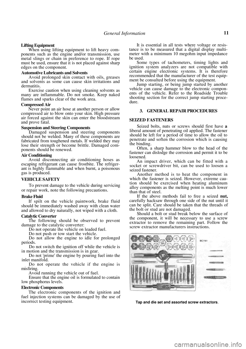
Should a bolt or stud break below the surface of
the component, it will be necessary to use a screw
extractor to remove the remaining part. Follow the
screw extractor manuf acturers instructions.
Tap and die set and assorted screw extractors.
Page 84 of 238
Fuel and Engine Management
(4) MAP sensor faulty or supply hose discon-
nected or blocked: Check the vacuum supply hose.
Check the operation of the MAP sensor.
EXCESSIVE FUEL CONSUMPTION
(1) Blocked air cleaner element: Check the ele-
ment and clean or renew as necessary.
(2) Incorrect fuel pressure: Check the fuel pump
and fuel pressure regulator. (3) Faulty coolant temperature sensor: Check
the connections and operation.
(4) Leaks in the fuel supply system: Check the
connections and components for leakage. (5) Leaking fuel injector(s): Clean or renew the
faulty injector(s). (6) Engine operating temperature too low:
Check the thermostat and electric cooling fan as
described in the Cooling an d Heating Systems section.
2. DESCRIPTION
The engine management system on the range of
vehicles covered by this manual controls the opera-
tion of the ignition system and the fuel system.
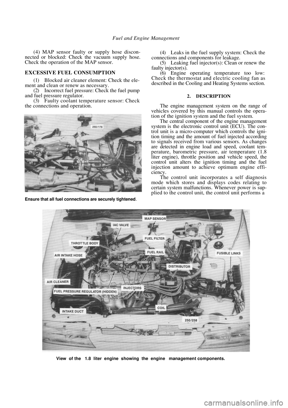
The central component of the engine management
system is the electronic control unit (ECU). The con-
trol unit is a micro-computer which controls the igni-
tion timing and the amount of fuel injected according
to signals received from various sensors. As changes
are detected in engine load and speed, coolant tem-
perature, barometric pressure, air temperature (1.8
liter engine), throttle position and vehicle speed, the
control unit alters the ignition timing and the fuel
injection amount to achieve optimum engine effi-
ciency.
The control unit incorporates a self diagnosis
mode which stores and displays codes relating to
certain system malfunctions. Whenever power is sup-
plied to the control unit, the control unit performs a
View of the 1.8 liter engine showing the engine management components.
Ensure that all fuel connections are securely tightened.
Page 86 of 238
86 Fuel and Engine Management
other. The fuel pressure is maintained at a constant
pressure relevant to the manifold vacuum. A dispos-
able paper element fuel filter is mounted on the engine
bulkhead.
The amount of fuel injected is relevant to the time
the injector remains open. The basic time the injector
remains open is governed by the control unit which
uses information from the various sensors to give
optimum engine efficiency for given conditions.
The idle air control (IAC) valve controls the fast
idle speed during engine warm up and maintains the
basic idle speed at a set value by compensating for
loads such as air conditioning or the selection of Drive
on automatic transaxle models.
The throttle body assembly is mounted to the
inlet manifold and controls the amount of air entering
the engine by the action of the throttle valve.
Efficient operation of the EFI system depends on
accurate signals being receiv ed by the control unit and
controlled air flow beyond the throttle valve. There-
fore it is essential that all air, fuel and electrical
connections be clean and tight.
3. SERVICE PRECAUTIONS AND
PROCEDURES
Electronic ignition systems can produce danger-
ously high voltages in both the primary and secondary
circuits. For this reason, extreme care must be taken
when working on or near the ignition system.
Do not start the engine if the battery terminals are
not clean and tight.
Do not use the fast charge or boost settings on a
battery charger to start the engine.
Do not disconnect the battery terminals while the
engine is running.
Disconnect the battery terminals before charging
the battery.
Disconnect the negative ba ttery terminal before
working on the engine management system.
Do not subject the control unit to temperatures
above 80 deg C.
Ensure that all wiring connectors are clean and
tight.
Disconnect the battery terminals and the control
unit wiring connectors before attempting any welding
operations.
Do not direct a steam cleaning or pressure
washing nozzle at engine management components
when cleaning the engine.
Ensure that the ignition is Off prior to disconnect-
ing the battery terminals, fusible links or the control
unit wiring connectors.
TO CONNECT ELECTRICAL TEST
EQUIPMENT
NOTE: Some types of tachometers, timing
lights and ignition system analysers are not
compatible with this engine management
system and may result in incorrect readings.
It is therefore recommended that the man-
ufacturer of the lest equipment be consulted
before proceeding to use the equipment.
If a test procedure requires the use of a
test lamp or voltmeter, ensure that only the
specified instrument is used to prevent mis-
leading diagnosis.
MULTIMETER
It is essential that in all tests where voltage or
resistance is to be measur ed, a digital display multi-
meter with a minimum 10 megohms impedance be
used.
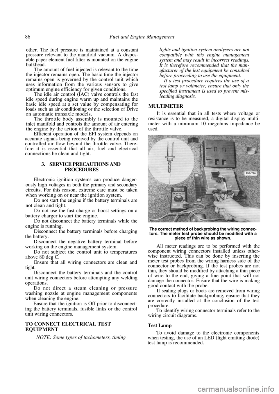
The correct method of backprobing the wiring connec-
tors. The meter test probe should be modified with a piece of thin wire as shown.
All meter readings are to be performed with the
component wiring connectors installed unless other-
wise instructed. This can be done by inserting the
meter test probes from the wiring harness side of the
connector or backprobing. If the test probes are not
thin, they should be modified by attaching a thin piece
of wire to the end, giving a fine point that will not
damage the connector. Ensure that the wire is making
good contact with the probe.
If sealing plugs or boots are removed from wiring
connectors to facilitate bac kprobing, ensure that they
are correctly installed at the conclusion of the test
procedure.
To identify wiring connector terminals refer to the
wiring circuit diagrams.
Test Lamp
To avoid damage to the electronic components
when testing, the use of an LED (light emitting diode)
test lamp is recommended.
Page 89 of 238
Fuel and Engine Management 89
The procedure for fabricating an LED test lamp is
fully described in the El ectrical System section.
If a conventional test lamp with a filament type
bulb is to be used, ensure that the current draw of the
test lamp does not exceed 0.3 amp to avoid damage to
the electronic components.
To check the current draw connect an accurate
ammeter, such as the multimeter described previ-
ously, in series with the test lamp and a battery.
If the ammeter reads less than 0.3 amp the test
lamp is suitable.
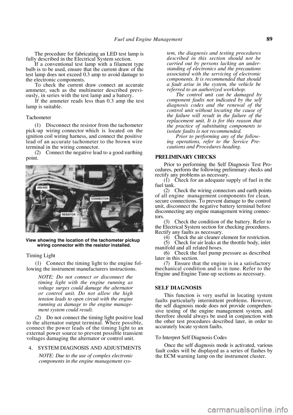
Tachometer
(1) Disconnect the resistor from the tachometer
pick-up wiring connector which is located on the
ignition coil wiring harness, and connect the positive
lead of an accurate tachometer to the brown wire
terminal in the wiring connector. (2) Connect the negative lead to a good earthing
point.
View showing the location of the tachometer pickup
wiring connector with the resistor installed.
Timing Light
(1) Connect the timing light to the engine fol-
lowing the instrument manufacturers instructions.
NOTE: Do not connect or disconnect the
timing light with the engine running as
voltage surges could damage the alternator
or control unit. Do not allow the high
tension leads to open circuit with the engine
running as damage to the engine manage-
ment system could result.
(2) Do not connect the timing light positive lead
to the alternator output terminal. Where possible,
connect the power leads of the timing light to an
external power source to prevent possible transient
voltages damaging the alternator or control unit.
4. SYSTEM DIAGNOSIS AND ADJUSTMENTS
NOTE: Due to the use of complex electronic
components in the engine management sys-
tem, the diagnosis and testing procedures
described in this section should not be
carried out by persons lacking an under-
standing of electronics and the precautions
associated with the servicing of electronic
components. It is rec ommended that should
a fault arise in the system, the vehicle be
referred to an authorized workshop.
The control unit can be damaged by
component faults not indicated by the self
diagnosis codes and the renewal of the
control unit without lo cating the cause of
the failure will result in the failure of the
replacement unit. It is for this reason that
the practice of substituting components to
isolate faults is not recommended.
Prior to performing any of the follow-
ing operations, refer to the Service Pre-
cautions and Procedures heading.
PRELIMINARY CHECKS
Prior to performing the Self Diagnosis Test Pro-
cedures, perform the following preliminary checks and
rectify any problems as necessary.
(1) Check for an adequate supply of fuel in the
fuel tank. (2) Check the wiring connectors and earth points
of all engine management components for clean,
secure connections. To prevent damage to the control
unit, disconnect the negative battery terminal before
disconnecting any engine ma nagement wiring connec-
tors. (3) Check the condition of the battery. Refer to
the Electrical System sectio n for checking procedures.
Rectify any faults as necessary. (4) Check the air cleaner element for restriction.
(5) Check for air leaks at the throttle body, inlet
manifold and all related hoses. (6) Check the fuel pump pr essure as described
later in this section. (7) Ensure that the engine is in a satisfactory
mechanical condition and is in tune. Refer to the
Engine and Engine Tune-up sections as necessary.
SELF DIAGNOSIS
This function is very useful in locating system
faults particularly intermittent problems. However,
the self diagnosis mode does not provide comprehen-
sive testing of the engine management system, and
therefore should always be used in conjunction with
the other test procedures described later, in order to
accurately locate system faults.
To Interpret Self Diagnosis Codes
Once the self diagnosis mode is activated, various
fault codes will be displayed as a series of flashes by
the ECM warning lamp on the instrument cluster.
Page 90 of 238
90 Fuel and Engine Management
To identify the code number, count the number of
times the ECM warning lamp flashes. Each fault code
comprises two groups of flashes separated by a 1.2
second pause. The first group represents tens and the
second group represents single units. For example 1
flash followed by a 1.2 second pause followed by 4
flashes would be code number 14. Similarly 4 flashes
followed by a 1.2 second pause followed by 2 flashes
would be code number 42.
The code will be displayed three times. If more
than one fault code is present, the self diagnosis
system will indicate each one in numerical order, with
a 3.2 second pause between each code, and then
repeat the sequence.
The fault codes can be identified as follows:
CODE NUMBER FAULT AREA
12 Satisfactory operation
13 Oxygen sensor open circuit
14 Coolant temperature sensor circuit (voltage low)
15 Coolant temperature sensor circuit (voltage high)
21 Throttle position sensor circuit (voltage high)
22Throttle position sensor circuit (voltage low)
23MAT sensor circuit (voltage' high) 1.8 liter engine
only
24 Vehicle speed sensor circuit
25 MAT sensor circuit
(voltage low) 1.8 liter engine
only
33 MAP sensor circuit
(voltage high)
34MAP sensor circuit (voltage low)
42 Electronic spark timing circuit
44
Oxygen sensor circuit
(lean exhaust)
45Oxygen sensor circuit (rich exhaust)
51 Mem-Cal
55 Control unit input circuits
Test Procedure
(1) Perform the following checks:
(a) Ensure that the battery voltage is above 11
volts. (b) Ensure that the throttle valve is fully closed.
(c) Place the transaxle in neutral.
(d) Ensure that the air conditioner, fan, tights
and all other accessories are switched off.
(2) Turn the ignition On and confirm that the
ECM warning lamp on the instrument cluster is
illuminated but not flashing.
If code 55 is displayed, refer to the Control Unit
heading, perform the circuit test procedure and rectify
the cause of the code before proceeding.
If the ECM warning lamp flashes codes other than
code 55, check the wiring harness between the diag-
nostic link connector terminal B and the control unit
wiring connector terminal A9 for shorts. Repair or
renew the wiring harness as necessary.
If no fault can be found, renew the control unit.
If the ECM warning lamp does not illuminate,
proceed as follows:
(a) Check the METER fuse located in the fuse
panel adjacent to the steering column and the fusible
links located in the fusible link connecting block at the
rear of the battery. Renew the fuse or fusible links as
necessary. (b) Check the wiring harness to the instrument
cluster. Repair or renew the harness. (c) Check the Check Engine lamp bulb. Renew if
necessary. (d) Check the EGI relay. Renew as necessary.
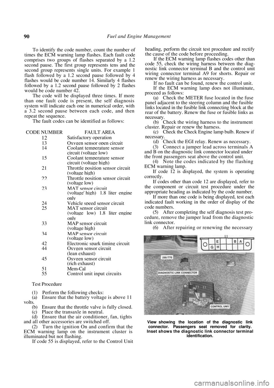
(3) Connect a jumper lead across terminals A
and B on the diagnostic link connector located under
the front passengers seat above the control unit.
(4) Note the codes indicated by the flashing
ECM warning lamp.
If code 12 is displayed, the system is operating
correctly.
If codes other than code 12 are displayed, refer to
the component or circuit test procedure under the
appropriate heading as indicated by the code number.
If more than one code is being displayed, test each
indicated fault working in the order of display of the
code numbers.
(5) After completing the self diagnosis test pro-
cedure, remove the jumper lead from the diagnostic
link connector. (6) After repairing or renewing the necessary
View showing the location of the diagnostic link
connector. Passengers seat removed for clarity.
Inset shows the diagnostic link connector terminal identification.
Page 91 of 238
Fuel and Engine Management 91
components, erase the self diagnosis memory as
described under the following heading.
(7) Repeat the self diagnosis test procedure and
ensure that code 12 is displayed.
To Erase Memory
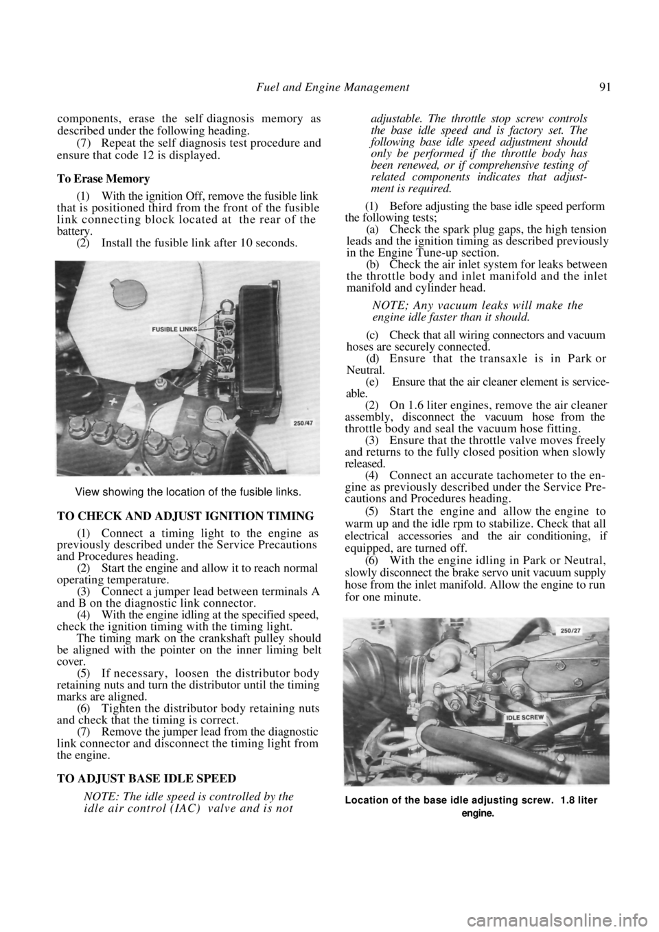
(1) With the ignition Off, remove the fusible link
that is positioned third from the front of the fusible
link connecting block located at the rear of the
battery. (2) Install the fusible link after 10 seconds.
View showing the location of the fusible links.
TO CHECK AND ADJUST IGNITION TIMING
(1) Connect a timing light to the engine as
previously described under the Service Precautions
and Procedures heading.
(2) Start the engine and allow it to reach normal
operating temperature. (3) Connect a jumper lead between terminals A
and B on the diagnostic link connector. (4) With the engine idling at the specified speed,
check the ignition timing with the timing light.
The timing mark on the crankshaft pulley should
be aligned with the pointer on the inner liming belt
cover.
(5) If necessary, loosen the distributor body
retaining nuts and turn the distributor until the timing
marks are aligned. (6) Tighten the distributor body retaining nuts
and check that the timing is correct. (7) Remove the jumper lead from the diagnostic
link connector and disconnect the timing light from
the engine.
TO ADJUST BASE IDLE SPEED
NOTE: The idle speed is controlled by the
idle air control (IAC) valve and is not
adjustable. The throttle stop screw controls
the base idle speed a nd is factory set. The
following base idle speed adjustment should
only be performed if the throttle body has
been renewed, or if comprehensive testing of
related components indicates that adjust-
ment is required.
(1) Before adjusting the base idle speed perform
the following tests;
(a) Check the spark plug gaps, the high tension
leads and the ignition timin g as described previously
in the Engine Tune-up section.
(b) Check the air inlet syst em for leaks between
the throttle body and inlet manifold and the inlet
manifold and cylinder head.
NOTE; Any vacuum leaks will make the
engine idle faster than it should.
(c) Check that all wiring connectors and vacuum
hoses are securely connected. (d) Ensure that the transaxle is in Park or
Neutral. (e) Ensure that the air cleaner element is service-
able.
(2) On 1.6 liter engines, remove the air cleaner
assembly, disconnect the vacuum hose from the
throttle body and seal the vacuum hose fitting.
(3) Ensure that the throttle valve moves freely
and returns to the fully closed position when slowly
released. (4) Connect an accurate tachometer to the en-
gine as previously descri bed under the Service Pre-
cautions and Procedures heading.
(5) Start the engine and allow the engine to
warm up and the idle rpm to stabilize. Check that all
electrical accessories and the air conditioning, if
equipped, are turned off. (6) With the engine idling in Park or Neutral,
slowly disconnect the brake servo unit vacuum supply
hose from the inlet manifold. Allow the engine to run
for one minute.
Location of the base idle adjusting screw. 1.8 liter
engine.
Page 102 of 238
\(V2 Fuel and Engine Management
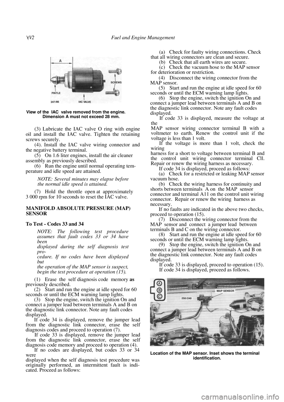
View of the IAC valve removed from the engine. Dimension A must not exceed 28 mm.
(3) Lubricate the IAC valve O ring with engine
oil and install the IAC valve. Tighten the retaining
screws securely.
(4). Install the IAC valve wiring connector and
the negative battery terminal.
(5) On 1.6 liter engines, install the air cleaner
assembly as previously described. (6) Run the engine until normal operating tem-
perature and idle speed are attained.
NOTE: Several minutes may elapse before
the normal idle speed is attained.
(7) Hold the throttle open at approximately
3 000 rpm for 10 seconds to reset the IAC valve.
MANIFOLD ABSOLUTE PRESSURE (MAP)
SENSOR
To Test - Codes 33 and 34
NOTE: The following test procedure
assumes that fault codes 33 or 34 have
been
displayed during the self diagnosis test
pro-
cedure. If no codes have been displayed
but
the operation of the MAP sensor is suspect,
begin the test procedure at operation (15).
(1) Erase the self diagnosis code memory as
previously described.
(2) Start and run the engine at idle speed for 60
seconds or until the ECM warning lamp lights.
(3) Stop the engine, switch the ignition On and
connect a jumper lead between terminals A and B on
the diagnostic link connector. Note any fault codes
displayed. If code 34 is displayed, remove the jumper lead
from the diagnostic link connector, erase the self
diagnosis codes and proceed to operation (7).
If code 33 is displayed, remove the jumper lead
from the diagnostic link connector, erase the self
diagnosis code memory and proceed to operation (4).
If no codes are displayed, but codes 33 or 34
were
displayed when the self diagnosis test procedure was
originally performed, an intermittent fault is indi-
cated. Proceed as follows:
(a) Check for faulty wiring connections. Check
that all wiring connectors are clean and secure. (b) Check that all earth wires are secure.
(c) Check the vacuum hose to the MAP sensor
for deterioration or restriction.
(4) Disconnect the wiring connector from the
MAP sensor. (5) Start and run the engine at idle speed for 60
seconds or until the ECM warning lamp lights. (6) Stop the engine, switch the ignition On and
connect a jumper lead between terminals A and B on
the diagnostic link connector. Note any fault codes
displayed.
If code 33 is displayed, measure the voltage at
the
MAP sensor wiring connector terminal B with a
voltmeter to earth. Renew the control unit if the
voltage is less than 1 volt.
If the voltage is more than 1 volt, check the
wiring
harness for a short to voltage between terminal B and
the control unit wiring connector terminal Cll.
Repair or renew the wiring harness as necessary.
If code 34 is displayed, proceed as follows:
(a) Check for a restricted or leaking MAP sensor
vacuum hose.
(b) Check the wiring harness for continuity and
shorts between terminals A on the MAP sensor
connector and terminal A11 on the control unit wiring
connector. Repair or renew the wiring harness as
necessary.
If no faults are indicated in the above two checks,
proceed to operation (15).
(7) Disconnect the wiring connector from the
MAP sensor and connect a jumper lead between
terminals B and C on the wiring connector. (8) Start and run the engine at idle speed for 60
seconds or until the ECM warning lamp lights. (9) Stop the engine, switch the ignition On and
connect a jumper lead between terminals A and B on
the diagnostic link connector. Note any fault codes
displayed.
If code 33 is displayed, proceed to operation (15).
If code 34 is displayed, proceed as follows.
Location of the MAP sensor. Inset shows the terminal
identification.
Page 106 of 238
106 Fuel and Engine Management
on the pickup coil wiring connector. The resistance
should be 500-1 500 ohms.
If the resistance is not as specified in either of the
above tests, renew the pickup coil.
(4) Remove the retaining spring from the dis-
tributor drive coupling.
(5) Using a pin punch, remove the drive pin
from the shaft. (6) Remove the drive coupling, washer, tang
washer and thrust spring from the shaft. (7) Remove the rotor and sh aft from the distrib-
utor housing. (8) Remove the retainer from the distributor
housing and withdraw the pickup coil. (9) Remove the retaining sc rews and remove the
control module from the distributor body. (10) Carefully lever the stationary pole from the
housing using a suitable screwdriver. Assembly is a reversal of the dismantling proce-
dure with attention to the following points:
(1) Ensure that the mating surfaces of the dis-
tributor housing and the control module are clean.
(2) Apply a silicone heat sink compound to the
surfaces between the control module and the distrib-
utor housing.
IGNITION COIL
To Test
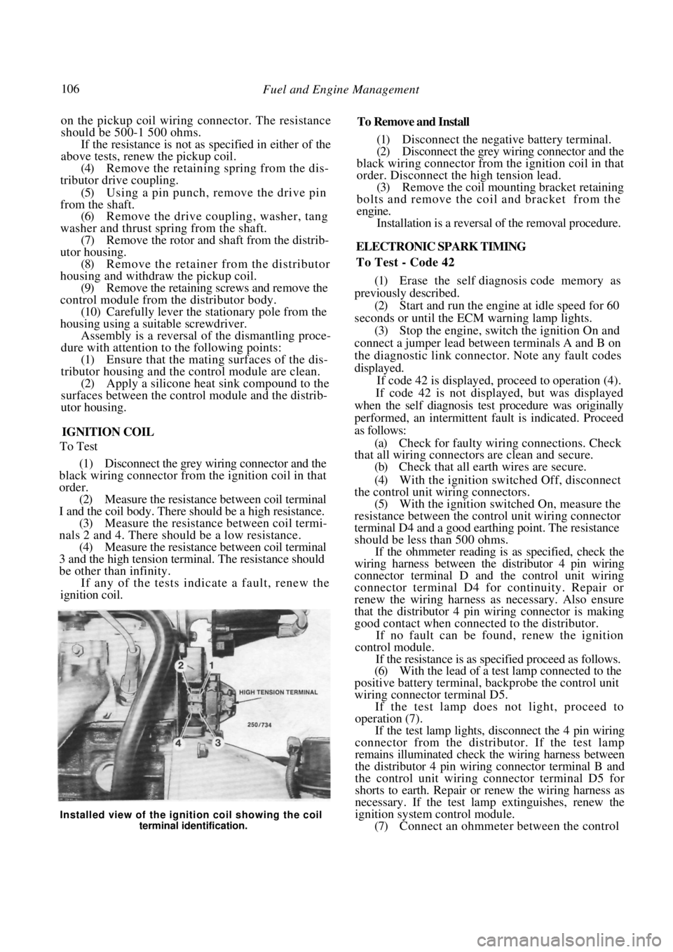
(1) Disconnect the grey wiring connector and the
black wiring connector from the ignition coil in that
order. (2) Measure the resistance between coil terminal
I and the coil body. There should be a high resistance. (3) Measure the resistance between coil termi-
nals 2 and 4. There should be a low resistance. (4) Measure the resistance between coil terminal
3 and the high tension termin al. The resistance should
be other than infinity.
If any of the tests indicate a fault, renew the
ignition coil.
To Remove and Install
(1) Disconnect the negative battery terminal.
(2) Disconnect the grey wiring connector and the
black wiring connector from the ignition coil in that
order. Disconnect the high tension lead. (3) Remove the coil mounting bracket retaining
bolts and remove the coil and bracket from the
engine. Installation is a reversal of the removal procedure.
ELECTRONIC SPARK TIMING
To Test - Code 42
(1) Erase the self diagnosis code memory as
previously described. (2) Start and run the engine at idle speed for 60
seconds or until the ECM warning lamp lights.
(3) Stop the engine, switch the ignition On and
connect a jumper lead between terminals A and B on
the diagnostic link connector . Note any fault codes
displayed. If code 42 is displayed, proceed to operation (4).
If code 42 is not displayed, but was displayed
when the self diagnosis test procedure was originally
performed, an intermittent fault is indicated. Proceed
as follows:
(a) Check for faulty wiri ng connections. Check
that all wiring connectors are clean and secure.
(b) Check that all earth wires are secure.
(4) With the ignition switched Off, disconnect
the control unit wiring connectors. (5) With the ignition switched On, measure the
resistance between the contro l unit wiring connector
terminal D4 and a good earthing point. The resistance
should be less than 500 ohms.
If the ohmmeter reading is as specified, check the
wiring harness between the distributor 4 pin wiring
connector terminal D and the control unit wiring
connector terminal D4 for continuity. Repair or
renew the wiring harness as necessary. Also ensure
that the distributor 4 pin wiring connector is making
good contact when connected to the distributor.
If no fault can be found, renew the ignition
control module.
If the resistance is as specified proceed as follows.
(6) With the lead of a test lamp connected to the
positive battery terminal, backprobe the control unit
wiring connector terminal D5.
If the test lamp does not light, proceed to
operation (7).
If the test lamp lights, disconnect the 4 pin wiring
connector from the distributor. If the test lamp
remains illuminated check the wiring harness between
the distributor 4 pin wiring connector terminal B and
the control unit wiring connector terminal D5 for
shorts to earth. Repair or renew the wiring harness as
necessary. If the test lamp extinguishes, renew the
ignition system control module.
(7) Connect an ohmmeter between the control
Installed view of the ignition coil showing the coil
terminal identification.
Page 107 of 238
Fuel and Engine Management 107
unit wiring connector terminal D4 and a good earth-
ing point.
(8) With the lead of a test lamp connected to the
positive battery terminal, backprobe the control unit
wiring connector terminal D5. As the test lamp probe
touches the terminal, the ohmmeter reading should
change from less than 500 ohms to over 5 000 ohms.
If the ohmmeter reading is not as specified,
proceed to operation (9).
If the ohmmeter reading is as specified, switch the
ignition Off and install the control unit wiring connec-
tors. Run the engine for 60 seconds or until the ECM
warning lamp lights and check for fault codes.
If code 42 is displayed renew the control unit.
If code 42 is not displayed, check the wiring
harness for continuity or sh orts between the control
unit wiring connector terminals D4 and D5 and the
distributor 4 pin wiring connector terminals D and B.
(9) Disconnect the 4 pin wiring connector from
the distributor.
(10) Check for continuity between the control
unit wiring connector termin al D4 and a good earth-
ing point. There should be no continuity.
If the continuity is not as specified, check the
wiring harness between the distributor 4 pin wiring
connector terminal D and the control unit wiring
connector terminal D4 for shorts to earth. Repair or
renew the wiring harness as necessary.
If the continuity is as specified, check the wiring
harness between the distributor 4 pin wiring connec-
tor terminal B and the control unit wiring connector
terminal D5 for continuity. Repair or renew the
wiring harness as necessary. If no fault is found, renew
the ignition system control module.
CONTROL UNIT
To Test Input Circuits — Code 55
(1) Switch the ignition On with the engine
stopped and note the ECM warning lamp. (2) If a steady light is showing, proceed to
operation (3). If code 55 is displayed, proceed as follows:
(a) Switch the ignition Off and disconnect the
wiring connector from the control unit.
(b) Switch the ignition On and measure the
voltage at the wiring connector on terminals C10,
C I 1 , C12, C13 and A9. Disregard terminal C12 on
1.6 liter engines. (c) If there is voltage at any of the terminals
tested above, a faulty wi ring harness is indicated.
Repair the short circuit to voltage and return to
operation (1). (d) If there is no voltage at any of the terminals
tested, a faulty control unit is indicated. Renew the
control unit and return to operation ( 1 ) . (3) Connect a jumper lead between terminals A
and B on the diagnostic link connector and note if
code 55 is displayed.
If code 55 is displayed, an intermittent fault is
indicated. Switch Off the engine, erase the self diag-
nosis codes and run the engine for 2 minutes. Return
to operation (1 ) and repeat the test procedures.
If code 55 continues to return, renew the control
unit.
To Remove and Install
(1) Disconnect the negative battery terminal.
(2) Slide the passengers front seat to the rear-
most position and working under the seat, disconnect
the control unit wiring connectors. (3) Disengage the plastic control unit cover from
the mounting plate and remove the control unit from
the vehicle. (4) If necessary, remove the screws retaining the
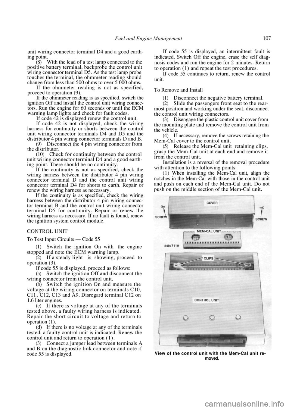
Mem-Cal cover to the control unit.
(5) Release the Mem-Cal unit retaining clips,
grasp the Mem-Cal unit at each end and remove it
from the control unit. Installation is a reversal of the removal procedure
with attention to the following points:
(1) When installing the Mem-Cal unit, align the
notches in the Mem-Cal with those in the control unit
and push on each end of the Mem-Cal unit. Do not
push on the middle section of the Mem-Cal unit.
View of the control unit with the Mem-Cal unit re-
moved.
Page 108 of 238
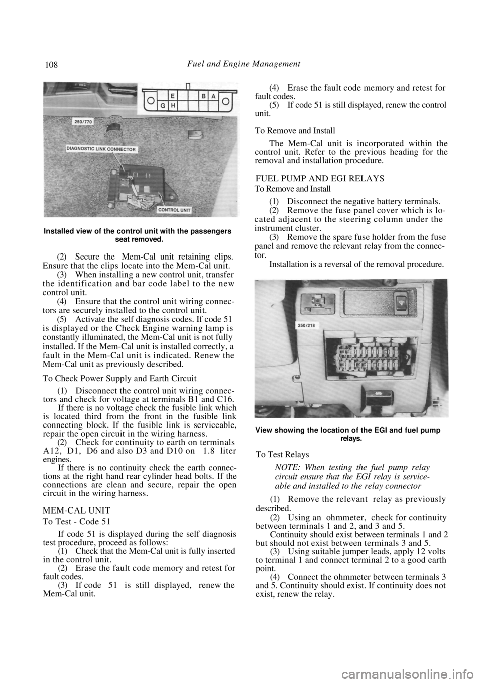
108 Fuel and Engine Management
Installed view of the control unit with the passengers seat removed.
(2) Secure the Mem-Cal unit retaining clips.
Ensure that the clips locate into the Mem-Cal unit. (3) When installing a new control unit, transfer
the identification and bar code label to the new
control unit. (4) Ensure that the control unit wiring connec-
tors are securely installed to the control unit. (5) Activate the self diagnosis codes. If code 51
is displayed or the Check Engine warning lamp is
constantly illuminated, the Mem-Cal unit is not fully
installed. If the Mem-Cal uni t is installed correctly, a
fault in the Mem-Cal unit is indicated. Renew the
Mem-Cal unit as previously described.
To Check Power Supply and Earth Circuit
(1) Disconnect the control unit wiring connec-
tors and check for voltage at terminals B1 and C16.
If there is no voltage check the fusible link which
is located third from the front in the fusible link
connecting block. If the fu sible link is serviceable,
repair the open circuit in the wiring harness.
(2) Check for continuity to earth on terminals
A12, D1, D6 and also D3 and D10 on 1.8 liter
engines.
If there is no continuity check the earth connec-
tions at the right hand rear cylinder head bolts. If the
connections are clean and secure, repair the open
circuit in the wiring harness.
MEM-CAL UNIT
To Test - Code 51
If code 51 is displayed during the self diagnosis
test procedure, pr oceed as follows:
(1) Check that the Mem-Cal unit is fully inserted
in the control unit. (2) Erase the fault code memory and retest for
fault codes. (3) If code 51 is still displayed, renew the
Mem-Cal unit.
(4) Erase the fault code memory and retest for
fault codes. (5) If code 51 is still displayed, renew the control
unit.
To Remove and Install
The Mem-Cal unit is incorporated within the
control unit. Refer to the previous heading for the
removal and installation procedure.
FUEL PUMP AND EGI RELAYS
To Remove and Install
(1) Disconnect the negative battery terminals.
(2) Remove the fuse panel cover which is lo-
cated adjacent to the steering column under the
instrument cluster. (3) Remove the spare fuse holder from the fuse
panel and remove the releva nt relay from the connec-
tor. Installation is a reversal of the removal procedure.
View showing the location of the EGI and fuel pump
relays.
To Test Relays
NOTE: When testing the fuel pump relay
circuit ensure that th e EGI relay is service-
able and installed to the relay connector
(1) Remove the relevant relay as previously
described. (2) Using an ohmmeter, check for continuity
between terminals 1 and 2, and 3 and 5. Continuity should exist be tween terminals 1 and 2
but should not exist between terminals 3 and 5.
(3) Using suitable jumper leads, apply 12 volts
to terminal 1 and connect terminal 2 to a good earth
point. (4) Connect the ohmmeter between terminals 3
and 5. Continuity should exist. If continuity does not
exist, renew the relay.