turn signal NISSAN QASHQAI 2015 Owner´s Manual
[x] Cancel search | Manufacturer: NISSAN, Model Year: 2015, Model line: QASHQAI, Model: NISSAN QASHQAI 2015Pages: 338, PDF Size: 4.88 MB
Page 210 of 338
– When strong light enters the camera unit.
(for example, light directly shines on the
front or rear of the vehicle at sunrise or
sunset.)
– When ambient brightness changes sud-
denly. (for example, when the vehicle en-
ters or exits a tunnel or passes under a
bridge.)
•Excessive noise (for example, audio system
volume, open vehicle window) will interfere
with the chime sound, and it may not be heard.
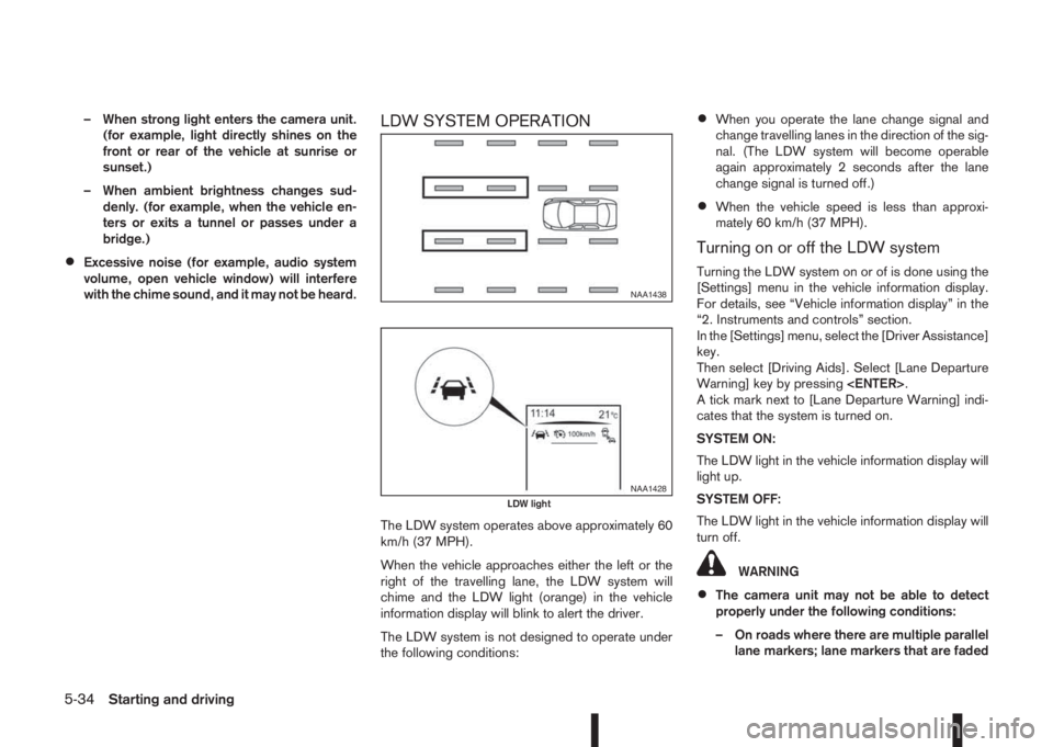
LDW SYSTEM OPERATION
The LDW system operates above approximately 60
km/h (37 MPH).
When the vehicle approaches either the left or the
right of the travelling lane, the LDW system will
chime and the LDW light (orange) in the vehicle
information display will blink to alert the driver.
The LDW system is not designed to operate under
the following conditions:
•When you operate the lane change signal and
change travelling lanes in the direction of the sig-
nal. (The LDW system will become operable
again approximately 2 seconds after the lane
change signal is turned off.)
•When the vehicle speed is less than approxi-
mately 60 km/h (37 MPH).
Turning on or off the LDW system
Turning the LDW system on or of is done using the
[Settings] menu in the vehicle information display.
For details, see “Vehicle information display” in the
“2. Instruments and controls” section.
In the [Settings] menu, select the [Driver Assistance]
key.
Then select [Driving Aids]. Select [Lane Departure
Warning] key by pressing
A tick mark next to [Lane Departure Warning] indi-
cates that the system is turned on.
SYSTEM ON:
The LDW light in the vehicle information display will
light up.
SYSTEM OFF:
The LDW light in the vehicle information display will
turn off.
WARNING
•The camera unit may not be able to detect
properly under the following conditions:
– On roads where there are multiple parallel
lane markers; lane markers that are faded
NAA1438
NAA1428LDW light
5-34Starting and driving
Page 224 of 338
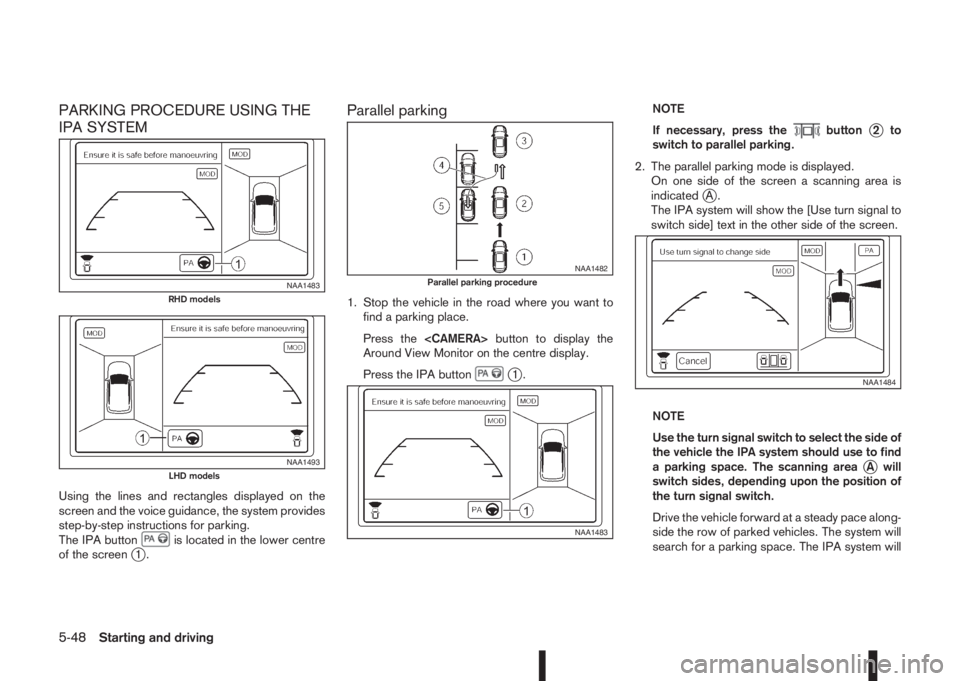
PARKING PROCEDURE USING THE
IPA SYSTEM
Using the lines and rectangles displayed on the
screen and the voice guidance, the system provides
step-by-step instructions for parking.
The IPA button
is located in the lower centre
of the screenj1.
Parallel parking
1. Stop the vehicle in the road where you want to
find a parking place.
Press the
Around View Monitor on the centre display.
Press the IPA button
j1.NOTE
If necessary, press the
buttonj2to
switch to parallel parking.
2. The parallel parking mode is displayed.
On one side of the screen a scanning area is
indicated
jA.
The IPA system will show the [Use turn signal to
switch side] text in the other side of the screen.
NOTE
Use the turn signal switch to select the side of
the vehicle the IPA system should use to find
a parking space. The scanning area
jA will
switch sides, depending upon the position of
the turn signal switch.
Drive the vehicle forward at a steady pace along-
side the row of parked vehicles. The system will
search for a parking space. The IPA system will
NAA1483RHD models
NAA1493LHD models
NAA1482Parallel parking procedure
NAA1483
NAA1484
5-48Starting and driving
Page 226 of 338
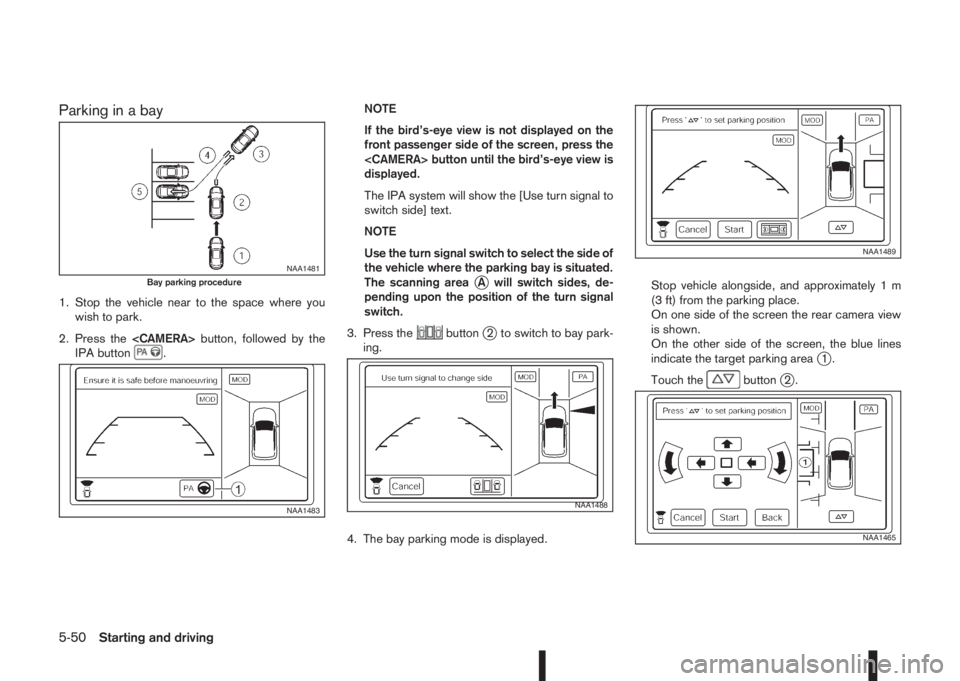
Parking in a bay
1. Stop the vehicle near to the space where you
wish to park.
2. Press the
IPA button
.NOTE
If the bird’s-eye view is not displayed on the
front passenger side of the screen, press the
displayed.
The IPA system will show the [Use turn signal to
switch side] text.
NOTE
Use the turn signal switch to select the side of
the vehicle where the parking bay is situated.
The scanning area
jA will switch sides, de-
pending upon the position of the turn signal
switch.
3. Press the
buttonj2 to switch to bay park-
ing.
4. The bay parking mode is displayed.Stop vehicle alongside, and approximately 1 m
(3 ft) from the parking place.
On one side of the screen the rear camera view
is shown.
On the other side of the screen, the blue lines
indicate the target parking area
j1.
Touch the
buttonj2.
NAA1481Bay parking procedure
NAA1483NAA1488
NAA1489
NAA1465
5-50Starting and driving
Page 232 of 338
TRAILER DETECTION (where fitted)
When towing a trailer and the turn signal switch is
used, the electrical system of the vehicle will detect
an additional electrical load of the trailer lighting. As
a result, the trailer direction indicator light comes
on.
INSTALLATION OF COUPLING
DEVICE (except for Australia)
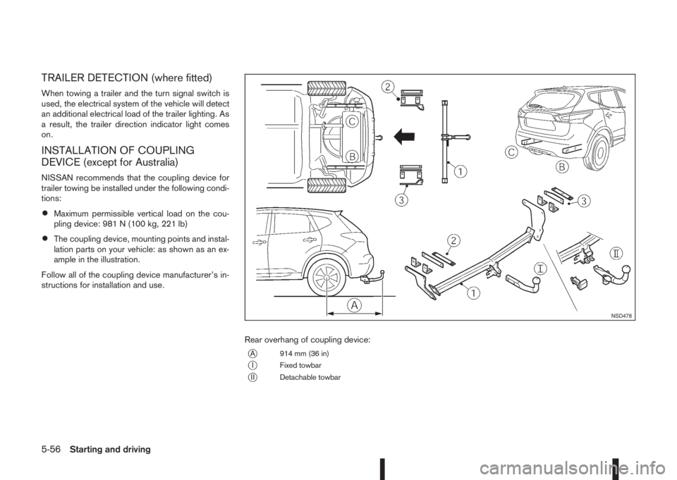
NISSAN recommends that the coupling device for
trailer towing be installed under the following condi-
tions:
•Maximum permissible vertical load on the cou-
pling device: 981 N (100 kg, 221 lb)
•The coupling device, mounting points and instal-
lation parts on your vehicle: as shown as an ex-
ample in the illustration.
Follow all of the coupling device manufacturer’s in-
structions for installation and use.
Rear overhang of coupling device:
jA 914 mm (36 in)
jI Fixed towbar
jII Detachable towbar
NSD478
5-56Starting and driving
Page 247 of 338
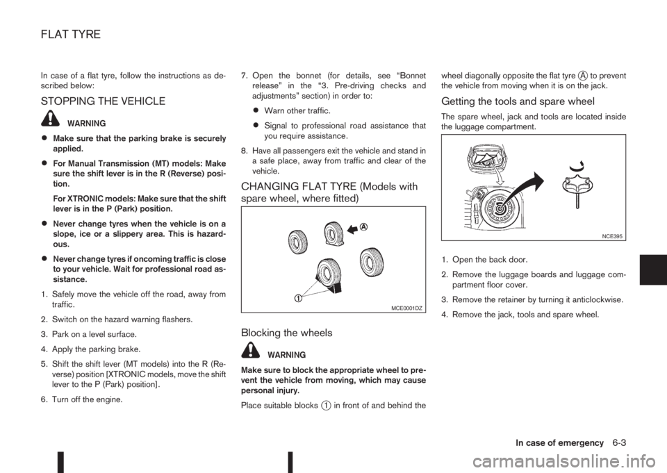
In case of a flat tyre, follow the instructions as de-
scribed below:
STOPPING THE VEHICLE
WARNING
•Make sure that the parking brake is securely
applied.
•For Manual Transmission (MT) models: Make
sure the shift lever is in the R (Reverse) posi-
tion.
For XTRONIC models: Make sure that the shift
lever is in the P (Park) position.
•Never change tyres when the vehicle is on a
slope, ice or a slippery area. This is hazard-
ous.
•Never change tyres if oncoming traffic is close
to your vehicle. Wait for professional road as-
sistance.
1. Safely move the vehicle off the road, away from
traffic.
2. Switch on the hazard warning flashers.
3. Park on a level surface.
4. Apply the parking brake.
5. Shift the shift lever (MT models) into the R (Re-
verse) position [XTRONIC models, move the shift
lever to the P (Park) position].
6. Turn off the engine.7. Open the bonnet (for details, see “Bonnet
release” in the “3. Pre-driving checks and
adjustments” section) in order to:
•Warn other traffic.
•Signal to professional road assistance that
you require assistance.
8. Have all passengers exit the vehicle and stand in
a safe place, away from traffic and clear of the
vehicle.
CHANGING FLAT TYRE (Models with
spare wheel, where fitted)
Blocking the wheels
WARNING
Make sure to block the appropriate wheel to pre-
vent the vehicle from moving, which may cause
personal injury.
Place suitable blocks
j1 in front of and behind thewheel diagonally opposite the flat tyre
jA to prevent
the vehicle from moving when it is on the jack.
Getting the tools and spare wheel
The spare wheel, jack and tools are located inside
the luggage compartment.
1. Open the back door.
2. Remove the luggage boards and luggage com-
partment floor cover.
3. Remove the retainer by turning it anticlockwise.
4. Remove the jack, tools and spare wheel.
MCE0001DZ
NCE395
FLAT TYRE
In case of emergency6-3
Page 251 of 338
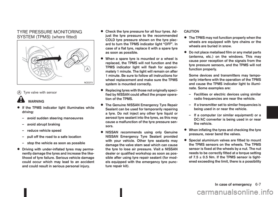
TYRE PRESSURE MONITORING
SYSTEM (TPMS) (where fitted)
j
ATyre valve with sensor
WARNING
•If the TPMS indicator light illuminates while
driving:
– avoid sudden steering manoeuvres
– avoid abrupt braking
– reduce vehicle speed
– pull off the road to a safe location
– stop the vehicle as soon as possible
•Driving with under-inflated tyres may perma-
nently damage the tyres and increase the like-
lihood of tyre failure. Serious vehicle damage
could occur which may lead to an accident
and could result in serious personal injury.
•Check the tyre pressure for all four tyres. Ad-
just the tyre pressure to the recommended
COLD tyre pressure shown on the tyre plac-
ard to turn the TPMS indicator light “OFF”. In
case of a flat tyre, replace it with a spare tyre
as soon as possible.
•When a spare tyre is mounted or a wheel is
replaced, the TPMS will not function and the
TPMS indicator light will flash for approxi-
mately 1 minute. The light will remain on after
1 minute. Be sure to follow all instructions for
wheel replacement and make sure the TPMS
system is mounted correctly.
•Replacing tyres with those not originally speci-
fied by NISSAN could affect the proper opera-
tion of the TPMS.
•The Genuine NISSAN Emergency Tyre Repair
Sealant can be used for temporarily repairing
a tyre. Do not inject any other tyre liquid or
aerosol tyre sealant into the tyres, as this may
cause a malfunction of the tyre pressure sen-
sors.
•NISSAN recommends using only Genuine
NISSAN Emergency Tyre Sealant provided
with your vehicle. Other tyre sealants may
damage the valve stem seal which can cause
the tyre to lose air pressure. Visit a NISSAN
dealer or qualified workshop as soon as pos-
sible after using tyre repair sealant (for mod-
els equipped with the emergency tyre punc-
ture repair kit).CAUTION
•The TPMS may not function properly when the
wheels are equipped with tyre chains or the
wheels are buried in snow.
•Do not place metalised film or any metal parts
(antenna, etc.) on the windows. This may
cause poor reception of the signals from the
tyre pressure sensors, and the TPMS will not
function properly.
Some devices and transmitters may tempo-
rarily interfere with the operation of the TPMS
and cause the TPMS indicator light to illumi-
nate. Some examples are:
– Facilities or electric devices using similar
radio frequencies are near the vehicle.
– If a transmitter set to similar frequencies is
being used in or near the vehicle.
– If a computer (or similar equipment) or a
DC/AC converter is being used in or near
the vehicle.
•When inflating the tyres and checking the tyre
pressure, never bend the valves.
•Special aluminium valves are fitted to mount
the TPMS sensors on the wheels. The TPMS
sensor is fixed at the wheels by a nut. The nut
needs to be correctly fitted at a torque setting
of 7.5 ± 0.5 Nm. If the TPMS sensor is tight-
ened exceeding the limit, there is a possibility
NCE373
In case of emergency6-7
Page 271 of 338
Lights*:
Clean the headlights on a regular basis. Make sure
that the headlights, stop lights, tail lights, turn signal
lights, and other lights are all operating properly and
installed securely. Also check headlight aim.
Tyres*:
Check the pressure with a gauge periodically when
at a service station (including the spare) and adjust
to the specified pressure if necessary. Check care-
fully for damage, cuts or excessive wear.
Tyre rotation*:
Tyres should be rotated every 10,000 km (6,000
miles) for Two-Wheel Drive (2WD) models and
5,000 km (3,000 miles) for Four-Wheel Drive (4WD)
models. However, the timing for tyre rotation may
vary according to your driving habits and road sur-
face conditions.
Tyre Pressure Monitoring System (TPMS)
transmitter components (where fitted):
Replace the TPMS transmitter grommet seal, valve
core and cap when the tyres are replaced due to
wear or age.
Wheel alignment and balance:
If the vehicle pull to either side while driving on a
straight and level road, or if you detect uneven or
abnormal tyre wear, there may be a need for wheel
alignment. If the steering wheel or seat vibrates at
normal highway speeds, wheel balancing may be
needed.Wheel nuts:
When checking the tyres, make sure no wheel nuts
are missing, and check for any loose wheel nuts.
Tighten if necessary.
Windscreen:
Clean the windscreen on a regular basis. Check the
windscreen at least every six months for cracks or
other damage. Have a damaged windscreen re-
paired by a qualified repair facility.
Wiper blades*:
Check for cracks or wear if they do not wipe prop-
erly.
Under the bonnet and vehicle
The maintenance items listed here should be
checked periodically, e.g. each time you check the
engine oil or refuel.
Battery*:
Check if the green indicator on the top of the main-
tenance free battery is visible. If it is not visible,
replace the battery as soon as possible.
Vehicles operated in high temperatures or under
severe conditions, check the fluid level frequently.
Brake and clutch fluid level*:
Make sure that the brake and clutch fluid level is
between the MAX and MIN lines on the reservoir.
Engine coolant level*:
Check the coolant level when the engine is cold.Engine drive belts*:
Make sure that the drive belts are not frayed, worn,
cracked or oily.
Engine oil level*:
Check the level after parking the vehicle on a level
surface and turning off the engine.
Fluid leaks:
Check under the vehicle for fuel, oil, water or other
fluid leaks after the vehicle has been parked for a
while. Water dripping from the air conditioner after
use is normal. If you should notice any leaks or if
petrol fumes are evident, check for the cause and
have it corrected immediately.
Window washer fluid*:
Check that there is adequate fluid in the tank.
Inside the vehicle
The maintenance items listed here should be
checked on a regular basis, such as when perform-
ing periodic maintenance, cleaning the vehicle, etc.
Accelerator pedal:
Check the pedal for smooth operation and make
sure that the pedal does not catch or require uneven
effort. Keep the floor mats away from the pedal.
Brake pedal*:
Check the pedal for smooth operation. If the brake
pedal suddenly goes down further than normal, the
pedal feels spongy or the vehicle seems to take
Maintenance and do-it-yourself8-3
Page 297 of 338
8. Where removed (step 3.), re-install the air duct,
bolt and clips in the reverse order of removal.
9. Reconnect the negative (—) battery cable and
close the bonnet.
NOTE
Fog may temporarily form inside the lens of the
exterior lights in the rain or in a car wash. The fog
is caused by a temperature difference between
the inside and the outside of the lens. This is not
a malfunction. If large droplets can be seen, then
contact a NISSAN dealer or qualified workshop.EXTERIOR LIGHTS
Item Wattage (W)
Front combination light
Headlight (Low beam: H11
type)55
Headlight (High beam: H7
type)60
Headlight (Low or high beam:
LED type, where fitted) *1LED
Front turn signal light 21
Front side light *1 LED
Front fog light (H8 type, where
fitted) *135
Side turn signal light *1 LED
Rear combination light
Turn signal light 21
Stop/Tail light *1 LED
Reverse light *1 16
High-mounted stop light *1 LED
Number plate light 5
Rear fog light 21
*1: If replacement is required, contact a NISSAN dealer
or qualified workshop.
INTERIOR LIGHTS
Item Wattage
(W)
Room light/Map lights (where fitted)
Foot well light (where fitted)5
3
Room light — rear (where fitted) 5
Reading lights — rear (where fitted) 8
Luggage compartment light 5
Maintenance and do-it-yourself8-29
Page 298 of 338
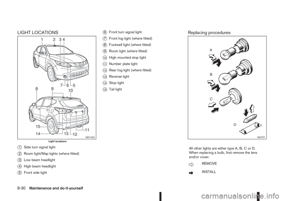
LIGHT LOCATIONS
j
1Side turn signal light
j2Room light/Map lights (where fitted)
j3Low beam headlight
j4High beam headlight
j5Front side light
j6Front turn signal light
j7Front fog light (where fitted)
j8Footwell light (where fitted)
j9Room light (where fitted)
j10High mounted stop light
j11Number plate light
j12Rear fog light (where fitted)
j13Reverse light
j14Stop light
j15Tail light
Replacing procedures
All other lights are either type A, B, C or D.
When replacing a bulb, first remove the lens
and/or cover.
mREMOVE
mINSTALL
NDI1453Light locationsNDI707
8-30Maintenance and do-it-yourself
Page 299 of 338
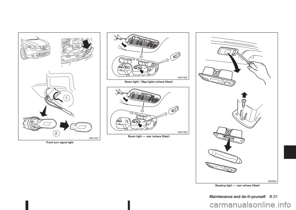
NDI1437Front turn signal light
NDI740ZRoom light / Map lights (where fitted)
NDI739ZRoom light — rear (where fitted)
NDI933Reading light — rear (where fitted)
Maintenance and do-it-yourself8-31