brake NISSAN QASHQAI 2017 Owner´s Manual
[x] Cancel search | Manufacturer: NISSAN, Model Year: 2017, Model line: QASHQAI, Model: NISSAN QASHQAI 2017Pages: 508, PDF Size: 2.68 MB
Page 107 of 508
2-28Instruments and controls
VEHICLE INFORMATION DISPLAY
WARNINGS AND INDICATORS
1. Engine start operation indicator (for
Continuously Variable Transmission
(CVT) models)
This indicator appears when the shift lever is in
the P (Park) position.
This indicator means that the engine will start by
pushing the ignition switch with the brake pedal
depressed. You can start the engine directly in
any position of the ignition switch.
2. Engine start operation indicator (for
Manual Transmission (MT) models)
This indicator means that the engine will start by
pushing the ignition switch with the clutch pedal
depressed. You can start the engine directly in
any position of the ignition switch.
You can also start the engine by pushing the
ignition switch with the brake pedal depressed
when the shift lever is in the N (Neutral) position.
3. No Key detected warning (if so
equipped)
This warning appears when the door is closed
with the Intelligent Key left outside the vehicle
and the ignition switch in the ON position. Make
sure that the Intelligent Key is inside the vehicle.See “Intelligent Key system” (P.3-11) for more
details.
4. Shift to Park warning (CVT models) (if
so equipped)
This warning appears when the ignition switch is
pushed to stop the engine with the shift lever in
any position except the P (Park) position.
If this warning appears, move the shift lever to
the P (Park) position or place the ignition switch
in the ON position.
An inside warning chime will also sound. (See
“Intelligent Key system” (P.3-11) .)
5. Key battery low warning (if so
equipped)
This warning appears when the Intelligent Key
battery is running out of power.
If this indicator appears, replace the battery with
a new one. See “Intelligent Key battery replace-
ment” (P.8-23) .
6. Engine start operation for Intelligent
Key system indicator (if so equipped)
This indicator appears when the Intelligent Key
battery is running out of power and when the
Intelligent Key system and vehicle are not
communicating normally.
If this indicator appears, touch the ignitionswitch with the Intelligent Key while depressing
the brake pedal. (See “Intelligent Key battery
discharge” (P.5-16).)
7. Key ID incorrect warning (if so
equipped)
This warning appears when the ignition switch is
placed from the LOCK position and the Intelli-
gent Key cannot be recognized by the system.
You cannot start the engine with an unregistered
key. Use the registered Intelligent Key.
See “Intelligent Key system” (P.3-11) .
8. Release Parking Brake warning
This warning appears when the vehicle speed is
above 4 MPH (7 km/h) (models not equipped
with electronic parking brake) or 2 MPH (4
km/h) (models equipped with electronic parking
brake) and the parking brake is applied. Stop the
vehicle and release the parking brake.
9. Low fuel level warning
This warning appears when the fuel level in the
fuel tank is getting low. Refuel as soon as it is
convenient, preferably before the fuel gauge
reaches 0 (Empty) . There will be a small reserve
of fuel in the tank when the fuel gauge needle
reaches 0 (Empty) .
Page 111 of 508
2-32Instruments and controls
Check to see if the sensor area of the front
bumper is blocked. If the sensor area of the front
bumper is blocked, remove the blocking materi-
al. Restart the engine. If the warning light
continues to illuminate, have the Forward
Emergency Braking (FEB) system checked. It
is recommended that you visit a NISSAN dealer
for this service.
For more details, see “Forward Emergency
Braking (FEB)” (P.5-80) , “Forward Emergency
Braking (FEB) with pedestrian detection sys-
tem” (P.5-86) or “Intelligent Cruise Control
(ICC)” (P.5-60) .
37. Unavailable: Side Radar Obstruction
warning (if so equipped)
This warning appears when the Blind Spot
Warning (BSW)/Rear Cross Traffic Alert (RCTA)
system becomes unavailable because a radar
blockage is detected. (See “Blind Spot Warning
(BSW)” (P.5-42) or “Rear Cross Traffic Alert
(RCTA)” (P.5-51) .)
38. Press Brake Pedal warning (for
electronic parking brake equipped mod-
els)
This indicator appears in the following situa-
tions:.The driver tries to release the electronic
parking brake manually without depressing
the brake pedal.
.The vehicle is stopped on a steep hill and
there is a possibility of moving backward,
even if the electronic parking brake is
applied.
Page 114 of 508
— Reset the elapsed time and trip od-
ometer.
.All
— Reset all items of “Average Speed”,
“Elapsed time and trip odometer” and
“Fuel economy.”
Once the “Elapsed time and trip odometer 1” is
displayed, you can use
*2buttons to
switch between the “Elapsed time and trip
odometer 1” and “Elapsed time and trip
odometer 2.”
4-5. Fuel economy 1 and 2 (MPG, l
(litre)/100 km or km/l(litre))
Current fuel consumption:
The current fuel consumption mode shows the
current fuel consumption.
Average fuel consumption:
The average fuel consumption 1 mode shows
the average fuel consumption since the last
reset. The average fuel consumption 2 mode
shows the average fuel consumption since the
time the ignition switch was placed in the ON
position. The average fuel consumption 2 is
automatically reset each time the ignition is
placed in the OFF position.
Resetting is done by pushing the OK
*1button.
When the OK
*1button is pushed, the
following menu items are displayed..Cancel
— Return to the previous screen without
resetting.
.Fuel Economy
— Reset the fuel economy.
.All
— Reset all items of “Average Speed”,
“Elapsed time and trip odometer” and
“Fuel economy”.
Once the “Fuel economy 1” is displayed, you
can use
*2buttons to switch between the
“Fuel economy 1” and “Fuel economy 2”.
The display is updated every 30 seconds. For
about the first 1/3 mile (500 m) after a reset, the
display shows “——”.
6. Audio
The audio mode shows the status of audio
information.
7. Navigation (if so equipped)
When the route guidance is set in the navigation
system, this item shows the navigation route
information.
8. Compass (if so equipped)
This display indicates the heading direction of
the vehicle.
9. “4x4-i” display (if so equipped)
When the “4x4-i” display is selected, you can
view the distribution ratio of the transmission
torque to the front and rear wheels during
driving.
10. Chassis control
When Active Trace Control, Active Engine Brake
(Continuously Variable Transmission (CVT)
models) or Active Ride Control system is
operated, it shows the operating condition. It
also shows operating condition of Hill Start
Assist. See “Active Trace Control” (P.5-106) ,
“Active Engine Brake (Continuously Variable
Transmission (CVT) models)” (P.5-107) , “Active
Ride Control” (P.5-108) or “Hill Start Assist
system” (P.5-109)for more details.
11. Tire Pressures
The tire pressure mode shows the pressure of all
four tires while the vehicle is driven.
When the Tire Pressure Low — Add Air warning
appears, the display can be switched to the tire
pressure mode by pushing the OK
*1button to
reveal additional details on the displayed warn-
ing.
Instruments and controls2-35
Page 126 of 508
If the ambient image sensor is damaged due to
an accident, it is recommended you contact a
NISSAN dealer.
Battery saver system
.When the headlight switch is in theorposition while the ignition switch is in
the ON position, the lights will automatically
turn off within a period of time after the
ignition switch has been placed in the OFF
position.
.When the headlight switch remains in the
orposition after the lights auto-
matically turn off, the lights will turn on when
the ignition switch is placed in the ON
position.
CAUTION
.When you turn on the headlight
switch again after the lights auto-
matically turn off, the lights will not
turn off automatically. Be sure to
turn the light switch to the OFF
position when you leave the vehicle
for extended periods of time, other-
wise the battery will be discharged.
.Never leave the light switch on
when the engine is not running forextended periods of time even if the
headlights turn off automatically.
Daytime Running Light (DRL) system
The LED portion of the headlights automatically
illuminate at 100% intensity when the engine is
started and the parking brake released. The LED
Daytime Running Light (DRL) operate with the
headlight switch in the OFF position or in the
position. When you turn the headlight
switch to theposition for full illumination,
the LED lights switch from LED DRL to the park
function.
If the parking brake is applied before the engine
is started, the LED DRL do not illuminate. The
LED DRL illuminate when the parking brake is
released. The LED DRL will remain on until the
ignition switch is placed in the OFF position.
It is necessary at dusk to turn the headlight
switch ON for interior controls and switches to
illuminate, as those remain OFF while the switch
is in the OFF position.
WARNING
When the LED DRL system is active, tail
lights on your vehicle are not on. It is
necessary at dusk to turn on yourheadlights. Failure to do so could cause
an accident injuring yourself and
others.
Instruments and controls2-47
Page 130 of 508
The heater is controlled by a thermostat,
automatically turning the heater on and off.
The indicator light will remain on as long as
the switch is on.
When the vehicle’s interior is warmed, or
before you leave the vehicle, be sure to turn
off the switch.
JVI1593X
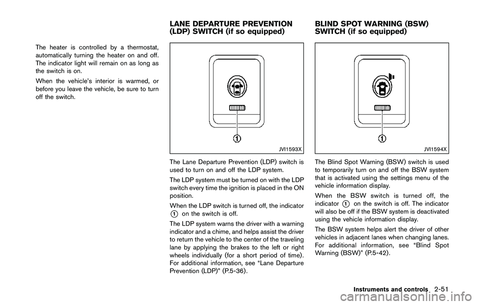
The Lane Departure Prevention (LDP) switch is
used to turn on and off the LDP system.
The LDP system must be turned on with the LDP
switch every time the ignition is placed in the ON
position.
When the LDP switch is turned off, the indicator
*1on the switch is off.
The LDP system warns the driver with a warning
indicator and a chime, and helps assist the driver
to return the vehicle to the center of the traveling
lane by applying the brakes to the left or right
wheels individually (for a short period of time) .
For additional information, see “Lane Departure
Prevention (LDP)” (P.5-36) .
JVI1594X
The Blind Spot Warning (BSW) switch is used
to temporarily turn on and off the BSW system
that is activated using the settings menu of the
vehicle information display.
When the BSW switch is turned off, the
indicator
*1on the switch is off. The indicator
will also be off if the BSW system is deactivated
using the vehicle information display.
The BSW system helps alert the driver of other
vehicles in adjacent lanes when changing lanes.
For additional information, see “Blind Spot
Warning (BSW)” (P.5-42) .
Instruments and controls2-51
LANE DEPARTURE PREVENTION
(LDP) SWITCH (if so equipped)BLIND SPOT WARNING (BSW)
SWITCH (if so equipped)
Page 137 of 508
2-58Instruments and controls
JVI1686X
Cargo area
LUGGAGE HOOKS
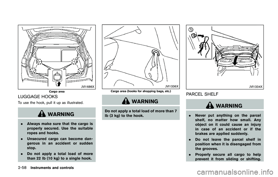
To use the hook, pull it up as illustrated.
WARNING
.Always make sure that the cargo is
properly secured. Use the suitable
ropes and hooks.
.Unsecured cargo can become dan-
gerous in an accident or sudden
stop.
.Do not apply a total load of more
than 22 lb (10 kg) to a single hook.
JVI1336X
Cargo area (hooks for shopping bags, etc.)
WARNING
Do not apply a total load of more than 7
lb (3 kg) to the hook.
JVI1334X
PARCEL SHELF
WARNING
.Never put anything on the parcel
shelf, no matter how small. Any
object on it could cause an injury
in case of an accident or if the
brakes are applied suddenly.
.Do not leave the parcel shelf in
position when it is disengaged from
the grooves.
.Properly secure all cargo to help
prevent it from sliding or shifting.
Page 170 of 508
The following events will occur when the engine
starts:
.The front parking lights will turn on and
remain on as long as the engine is running.
.The doors will be locked and the air
conditioner system may turn on.
.The engine will continue to run for about 10
minutes. Repeat the steps to extend the time
for an additional 10 minutes. See “Extending
engine run time” (P.3-23) .
Depress and hold the brake pedal, then place
the ignition switch in the ON position before
driving. For further instructions, see “Driving the
vehicle” (P.5-20) .
EXTENDING ENGINE RUN TIME
The remote engine start function can be
extended one time by performing the steps
listed in “Remote starting the engine” (P.3-22) .
Run time will be calculated as follows:
.The first 10 minute run time will start when
the remote engine start function is per-
formed.
.The second 10 minutes will start immedi-
ately when the remote engine start function
is performed. For example, if the engine has
been running for 5 minutes, and 10 minutes
are added, the engine will run for a total of
15 minutes..Extending engine run time will count to-
wards the two remote start limit.
A maximum of two remote starts, or a single start
with an extension, are allowed between ignition
cycles.
The ignition switch must be cycled to the ON
position and then back to the OFF position
before the remote engine start procedure can be
used again.
CANCELING A REMOTE START
To cancel a remote start, perform one of the
following:
.Aim the Intelligent Key at the vehicle and
push and hold the remote engine start
button until the front parking lights turn off.
.Turn on the hazard indicator flashers.
.Cycle the ignition switch ON and then OFF.
.The extended engine run time has expired.
.The first 10 minute timer has expired.
.The engine hood has been opened.
.The shift lever is moved out of the P (Park)
position.
.The theft alarm sounds due to illegal entry
into the vehicle.
.The ignition switch is pushed without an
Intelligent Key in the vehicle..The ignition switch is pushed with an
Intelligent Key in the vehicle but the brake
pedal is not depressed.
CONDITIONS THE REMOTE ENGINE
START WILL NOT WORK
The remote engine start will not operate if any of
the following conditions are present:
.The ignition switch is placed in the ON
position.
.The hood is not securely closed.
.The hazard indicator flashers are on.
.The engine is still running. The engine must
be completely stopped. Wait at least 6
seconds if the engine goes from running to
off. This is not applicable when extending
engine run time.
.The remote engine start
button is not
pushed and held for at least 2 seconds.
.The remote engine start
button is not
pushed and held within 5 seconds of
pushing the LOCK
button.
.The brake pedal is depressed.
.The doors are not closed and locked.
.The liftgate is open.
.The Key System Error warning message
remains on in the vehicle information display.
.An Intelligent Key is left inside the vehicle.
Pre-driving checks and adjustments3-23
Page 192 of 508
SAA3475
Backing up behind a projecting object
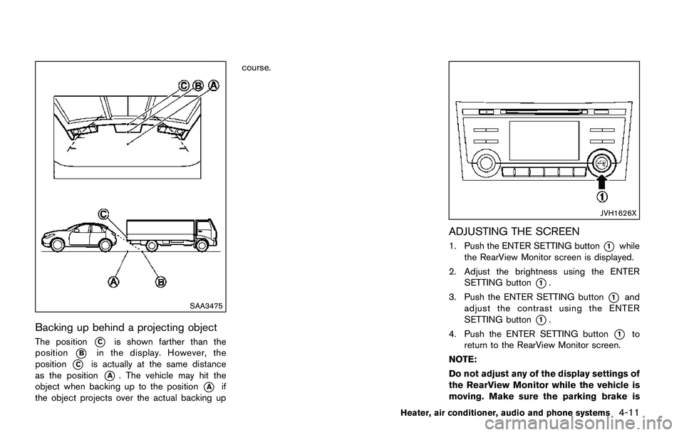
The position*Cis shown farther than the
position
*Bin the display. However, the
position
*Cis actually at the same distance
as the position
*A. The vehicle may hit the
object when backing up to the position
*Aif
the object projects over the actual backing upcourse.
JVH1626X
ADJUSTING THE SCREEN
1. Push the ENTER SETTING button*1while
the RearView Monitor screen is displayed.
2. Adjust the brightness using the ENTER
SETTING button
*1.
3. Push the ENTER SETTING button
*1and
adjust the contrast using the ENTER
SETTING button
*1.
4. Push the ENTER SETTING button
*1to
return to the RearView Monitor screen.
NOTE:
Do not adjust any of the display settings of
the RearView Monitor while the vehicle is
moving. Make sure the parking brake is
Heater, air conditioner, audio and phone systems4-11
Page 202 of 508
5. When the vehicle is parked in the space
completely, move the shift lever to the P
(Park) position and apply the parking brake.
HOW TO SWITCH THE DISPLAY
With the ignition switch placed in the ACC or
ON position, push the CAMERA button or move
the shift lever to the R (Reverse) position to
operate the Around View
�ŠMonitor.
The Around View�ŠMonitor displays different
split screen views depending on the position of
the shift lever. Push the CAMERA button to
switch between the available views.
If the shift lever is in the R (Reverse) position, the
available views are:
.Rear view/bird’s-eye view split screen
.Rear view/front-side view split screen
.Rear view
If the shift lever is in the P (Park) position, the
available views are:
.Front view/bird’s-eye view split screen
.Front view/front-side view split screen
The display will switch from the Around View
�Š
Monitor screen when:
.The shift lever is in the D (Drive) position and
the vehicle speed increases above approxi-
mately 6 MPH (10 km/h) ..A different screen is selected.
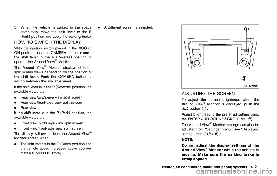
JVH1636X
ADJUSTING THE SCREEN
To adjust the screen brightness when the
Around View�ŠMonitor is displayed, push thebutton*1.
Adjust brightness to the preferred setting using
the ENTER AUDIO/TUNE·SCROLL dial
*2.
The Around View�ŠMonitor settings can also be
adjusted from “Settings” menu. (See “Displaying
settings menu” (P.4-5) .)
NOTE:
Do not adjust the display settings of the
Around View
�ŠMonitor while the vehicle is
moving. Make sure the parking brake is
firmly applied.
Heater, air conditioner, audio and phone systems4-21
Page 286 of 508
5 Starting and driving
Precautions when starting and driving ................................ 5-4
Exhaust gas (carbon monoxide) ...................................... 5-4
Three-way catalyst .............................................................. 5-5
Tire Pressure Monitoring System (TPMS) .................... 5-5
Avoiding collision and rollover ......................................... 5-8
On-pavement and off-road driving precautions .......... 5-8
Off-road recovery ................................................................ 5-9
Rapid air pressure loss ...................................................... 5-9
Drinking alcohol/drugs and driving .............................. 5-10
Driving safety precautions .............................................. 5-10
Ignition switch (models without Intelligent
Key system) ............................................................................. 5-12
Continuously Variable Transmission (CVT) ................ 5-13
Manual Transmission (MT) ............................................. 5-13
Key positions ..................................................................... 5-14
Push-button ignition switch (model with Intelligent
Key system) ............................................................................. 5-14
Operating range for engine start function ................. 5-14
Push-button ignition switch operation ........................ 5-15
Push-button ignition switch positions ......................... 5-16
Emergency engine shut off ............................................ 5-16
Intelligent Key battery discharge .................................. 5-16
Before starting the engine ................................................... 5-17
Starting the engine (model without Intelligent
Key system) ............................................................................. 5-17Starting the engine (model with Intelligent
Key system) ............................................................................ 5-18
Remote engine start (if so equipped) ...................... 5-19
Driving the vehicle ................................................................. 5-20
Continuously Variable Transmission (CVT) ............. 5-20
Manual Transmission (MT) ........................................... 5-25
Parking brake .......................................................................... 5-26
Pedal type ........................................................................ 5-27
Switch type (models with electronic parking
brake system) ................................................................. 5-27
ECO mode system ............................................................... 5-29
ECO Pedal Guide function ......................................... 5-29
Ambient ECO .................................................................. 5-30
ECO Drive Report ......................................................... 5-31
Lane Departure Warning (LDW) (if so equipped) ....... 5-31
LDW system operation ................................................. 5-32
How to enable/disable the LDW system ................. 5-33
LDW system limitations ................................................ 5-34
System temporarily unavailable .................................. 5-35
System malfunction ....................................................... 5-35
System maintenance ..................................................... 5-36
Lane Departure Prevention (LDP) (if so equipped) ..... 5-36
LDP system operation .................................................. 5-37
How to enable/disable the LDP system .................. 5-38
LDP system limitations ................................................. 5-39