NISSAN TEANA 2003 Service Manual
Manufacturer: NISSAN, Model Year: 2003, Model line: TEANA, Model: NISSAN TEANA 2003Pages: 3502, PDF Size: 74.56 MB
Page 2531 of 3502
POWER WINDOW SYSTEM
GW-37
C
D
E
F
G
H
J
K
L
MA
B
GW
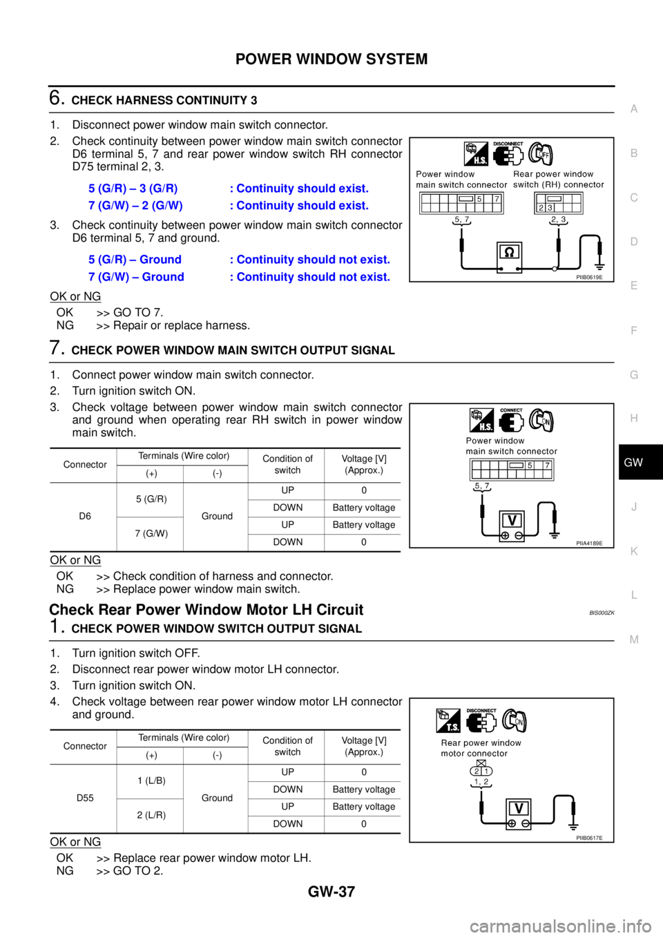
6. CHECK HARNESS CONTINUITY 3
1. Disconnect power window main switch connector.
2. Check continuity between power window main switch connector
D6 terminal 5, 7 and rear power window switch RH connector
D75 terminal 2, 3.
3. Check continuity between power window main switch connector
D6 terminal 5, 7 and ground.
OK or NG
OK >> GO TO 7.
NG >> Repair or replace harness.
7. CHECK POWER WINDOW MAIN SWITCH OUTPUT SIGNAL
1. Connect power window main switch connector.
2. Turn ignition switch ON.
3. Check voltage between power window main switch connector
and ground when operating rear RH switch in power window
main switch.
OK or NG
OK >> Check condition of harness and connector.
NG >> Replace power window main switch.
Check Rear Power Window Motor LH Circuit BIS000ZK
1. CHECK POWER WINDOW SWITCH OUTPUT SIGNAL
1. Turn ignition switch OFF.
2. Disconnect rear power window motor LH connector.
3. Turn ignition switch ON.
4. Check voltage between rear power window motor LH connector
and ground.
OK or NG
OK >> Replace rear power window motor LH.
NG >> GO TO 2.5 (G/R) – 3 (G/R) : Continuity should exist.
7 (G/W) – 2 (G/W) : Continuity should exist.
5 (G/R) – Ground : Continuity should not exist.
7 (G/W) – Ground : Continuity should not exist.
PIIB0619E
ConnectorTerminals (Wire color)
Condition of
switchVoltage [V]
(Approx.)
(+) (-)
D65 (G/R)
GroundUP 0
DOWN Battery voltage
7 (G/W)UP Battery voltage
DOWN 0
PIIA4189E
ConnectorTerminals (Wire color)
Condition of
switchVoltage [V]
(Approx.)
(+) (-)
D551 (L/B)
GroundUP 0
DOWN Battery voltage
2 (L/R)UP Battery voltage
DOWN 0
PIIB0617E
Page 2532 of 3502
GW-38
POWER WINDOW SYSTEM
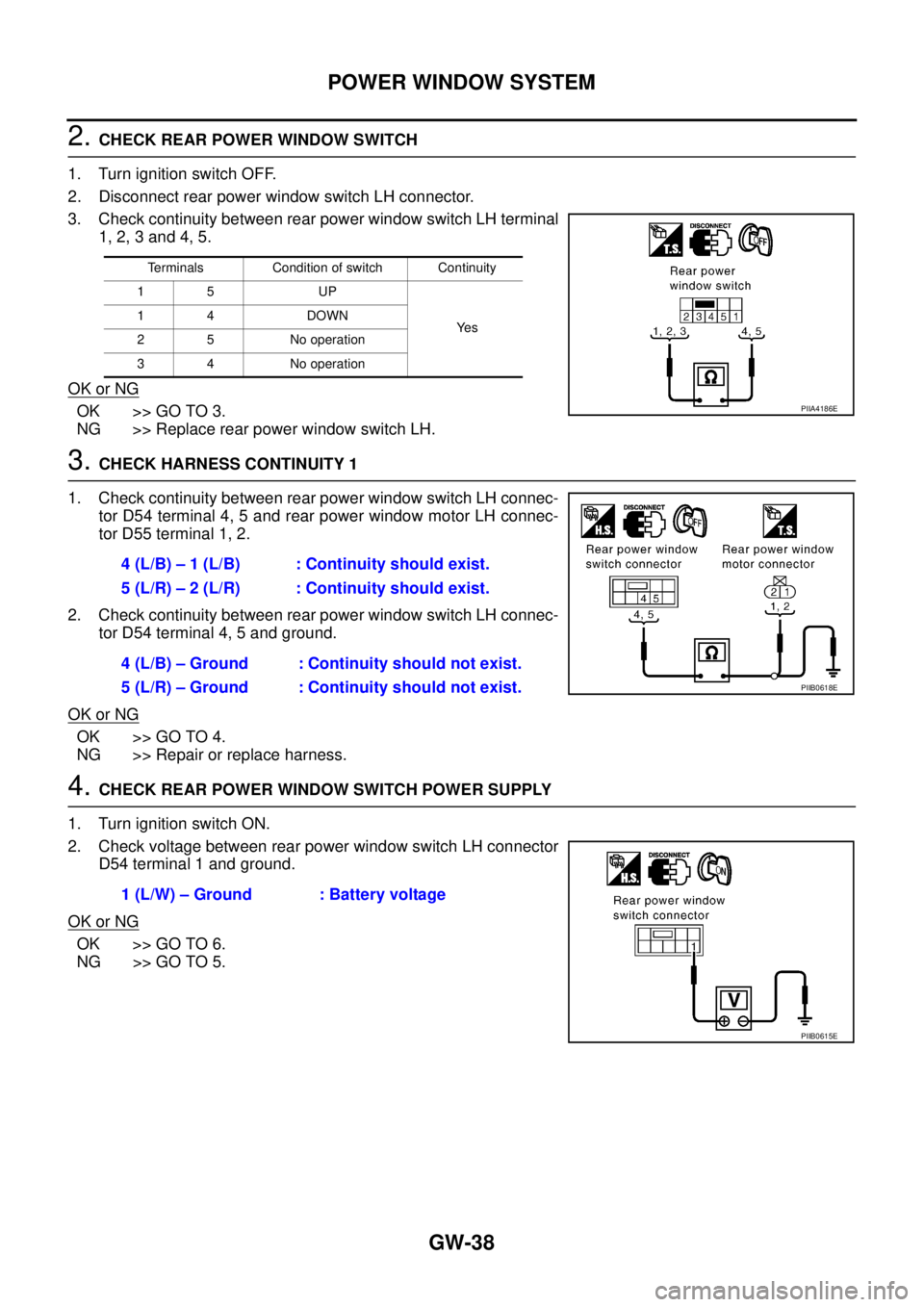
2. CHECK REAR POWER WINDOW SWITCH
1. Turn ignition switch OFF.
2. Disconnect rear power window switch LH connector.
3. Check continuity between rear power window switch LH terminal
1, 2, 3 and 4, 5.
OK or NG
OK >> GO TO 3.
NG >> Replace rear power window switch LH.
3. CHECK HARNESS CONTINUITY 1
1. Check continuity between rear power window switch LH connec-
tor D54 terminal 4, 5 and rear power window motor LH connec-
tor D55 terminal 1, 2.
2. Check continuity between rear power window switch LH connec-
tor D54 terminal 4, 5 and ground.
OK or NG
OK >> GO TO 4.
NG >> Repair or replace harness.
4. CHECK REAR POWER WINDOW SWITCH POWER SUPPLY
1. Turn ignition switch ON.
2. Check voltage between rear power window switch LH connector
D54 terminal 1 and ground.
OK or NG
OK >> GO TO 6.
NG >> GO TO 5.
Terminals Condition of switch Continuity
15 UP
Ye s 14 DOWN
2 5 No operation
3 4 No operation
PIIA4186E
4 (L/B) – 1 (L/B) : Continuity should exist.
5 (L/R) – 2 (L/R) : Continuity should exist.
4 (L/B) – Ground : Continuity should not exist.
5 (L/R) – Ground : Continuity should not exist.
PIIB0618E
1 (L/W) – Ground : Battery voltage
PIIB0615E
Page 2533 of 3502
POWER WINDOW SYSTEM
GW-39
C
D
E
F
G
H
J
K
L
MA
B
GW
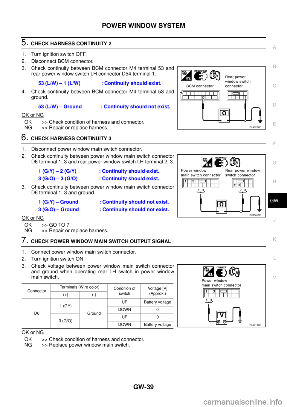
5. CHECK HARNESS CONTINUITY 2
1. Turn ignition switch OFF.
2. Disconnect BCM connector.
3. Check continuity between BCM connector M4 terminal 53 and
rear power window switch LH connector D54 terminal 1.
4. Check continuity between BCM connector M4 terminal 53 and
ground.
OK or NG
OK >> Check condition of harness and connector.
NG >> Repair or replace harness.
6. CHECK HARNESS CONTINUITY 3
1. Disconnect power window main switch connector.
2. Check continuity between power window main switch connector
D6 terminal 1, 3 and rear power window switch LH terminal 2, 3.
3. Check continuity between power window main switch connector
D6 terminal 1, 3 and ground.
OK or NG
OK >> GO TO 7.
NG >> Repair or replace harness.
7. CHECK POWER WINDOW MAIN SWITCH OUTPUT SIGNAL
1. Connect power window main switch connector.
2. Turn ignition switch ON.
3. Check voltage between power window main switch connector
and ground when operating rear LH switch in power window
main switch.
OK or NG
OK >> Check condition of harness and connector.
NG >> Replace power window main switch.53 (L/W) – 1 (L/W) : Continuity should exist.
53 (L/W) – Ground : Continuity should not exist.
PIIA6284E
1 (G/Y) – 2 (G/Y) : Continuity should exist.
3 (G/O) – 3 (G/O) : Continuity should exist.
1 (G/Y) – Ground : Continuity should not exist.
3 (G/O) – Ground : Continuity should not exist.
PIIB0616E
ConnectorTerminals (Wire color)
Condition of
switchVoltage [V]
(Approx.)
(+) (-)
D61 (GY)
GroundUP Battery voltage
DOWN 0
3 (G/O)UP 0
DOWN Battery voltage
PIIA4187E
Page 2534 of 3502
GW-40
POWER WINDOW SYSTEM
Check Limit Switch Circuit (Driver Side)BIS000ZL
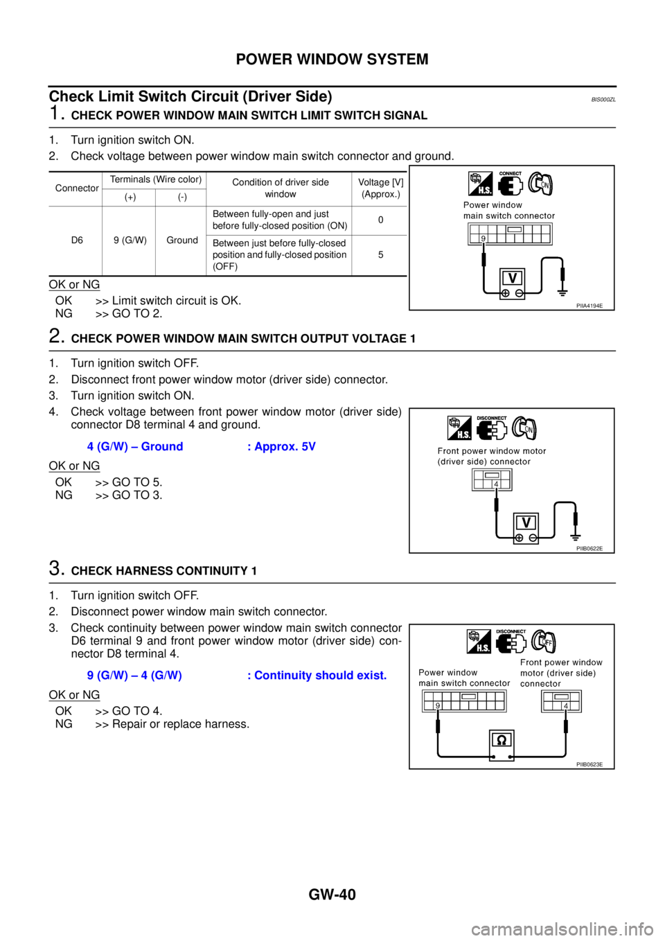
1. CHECK POWER WINDOW MAIN SWITCH LIMIT SWITCH SIGNAL
1. Turn ignition switch ON.
2. Check voltage between power window main switch connector and ground.
OK or NG
OK >> Limit switch circuit is OK.
NG >> GO TO 2.
2. CHECK POWER WINDOW MAIN SWITCH OUTPUT VOLTAGE 1
1. Turn ignition switch OFF.
2. Disconnect front power window motor (driver side) connector.
3. Turn ignition switch ON.
4. Check voltage between front power window motor (driver side)
connector D8 terminal 4 and ground.
OK or NG
OK >> GO TO 5.
NG >> GO TO 3.
3. CHECK HARNESS CONTINUITY 1
1. Turn ignition switch OFF.
2. Disconnect power window main switch connector.
3. Check continuity between power window main switch connector
D6 terminal 9 and front power window motor (driver side) con-
nector D8 terminal 4.
OK or NG
OK >> GO TO 4.
NG >> Repair or replace harness.
ConnectorTerminals (Wire color)
Condition of driver side
windowVoltage [V]
(Approx.)
(+) (-)
D6 9 (G/W) GroundBetween fully-open and just
before fully-closed position (ON)0
Between just before fully-closed
position and fully-closed position
(OFF)5
PIIA4194E
4 (G/W) – Ground : Approx. 5V
PIIB0622E
9 (G/W) – 4 (G/W) : Continuity should exist.
PIIB0623E
Page 2535 of 3502
POWER WINDOW SYSTEM
GW-41
C
D
E
F
G
H
J
K
L
MA
B
GW
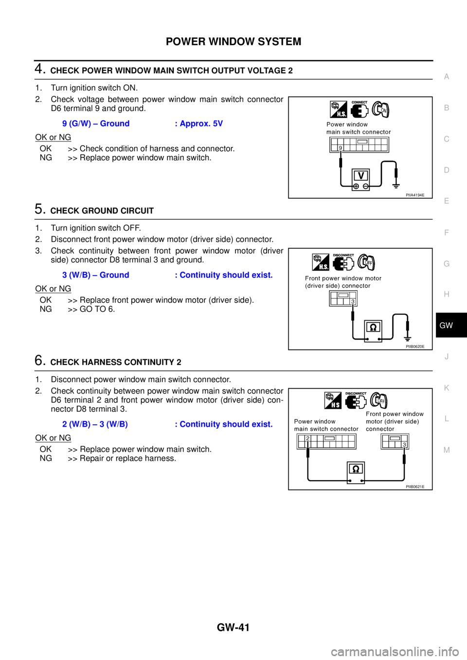
4. CHECK POWER WINDOW MAIN SWITCH OUTPUT VOLTAGE 2
1. Turn ignition switch ON.
2. Check voltage between power window main switch connector
D6 terminal 9 and ground.
OK or NG
OK >> Check condition of harness and connector.
NG >> Replace power window main switch.
5. CHECK GROUND CIRCUIT
1. Turn ignition switch OFF.
2. Disconnect front power window motor (driver side) connector.
3. Check continuity between front power window motor (driver
side) connector D8 terminal 3 and ground.
OK or NG
OK >> Replace front power window motor (driver side).
NG >> GO TO 6.
6. CHECK HARNESS CONTINUITY 2
1. Disconnect power window main switch connector.
2. Check continuity between power window main switch connector
D6 terminal 2 and front power window motor (driver side) con-
nector D8 terminal 3.
OK or NG
OK >> Replace power window main switch.
NG >> Repair or replace harness.9 (G/W) – Ground : Approx. 5V
PIIA4194E
3 (W/B) – Ground : Continuity should exist.
PIIB0620E
2 (W/B) – 3 (W/B) : Continuity should exist.
PIIB0621E
Page 2536 of 3502
GW-42
POWER WINDOW SYSTEM
Check Encoder Circuit (Driver Side) BIS000ZM
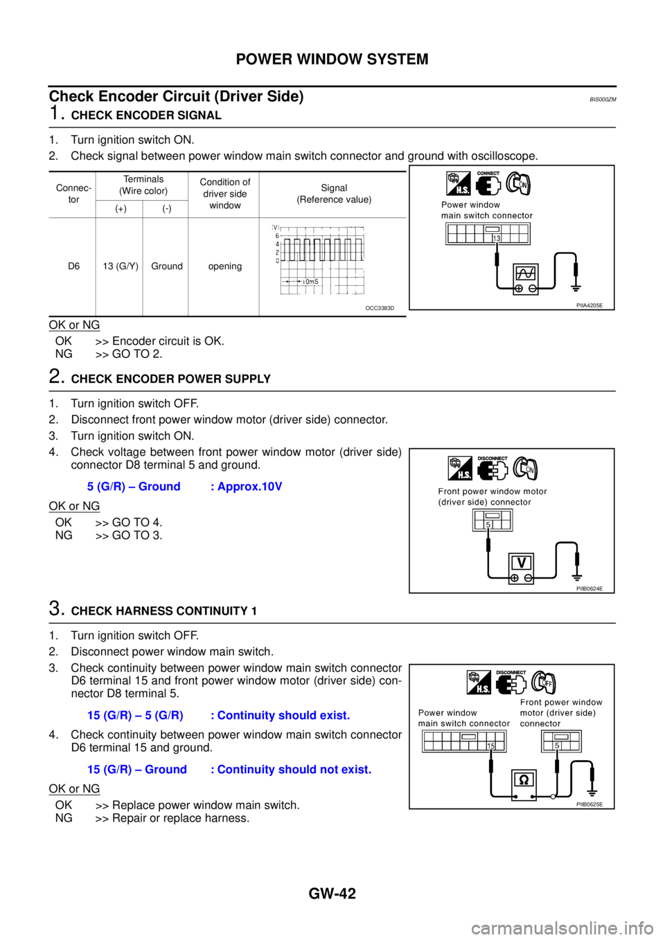
1. CHECK ENCODER SIGNAL
1. Turn ignition switch ON.
2. Check signal between power window main switch connector and ground with oscilloscope.
OK or NG
OK >> Encoder circuit is OK.
NG >> GO TO 2.
2. CHECK ENCODER POWER SUPPLY
1. Turn ignition switch OFF.
2. Disconnect front power window motor (driver side) connector.
3. Turn ignition switch ON.
4. Check voltage between front power window motor (driver side)
connector D8 terminal 5 and ground.
OK or NG
OK >> GO TO 4.
NG >> GO TO 3.
3. CHECK HARNESS CONTINUITY 1
1. Turn ignition switch OFF.
2. Disconnect power window main switch.
3. Check continuity between power window main switch connector
D6 terminal 15 and front power window motor (driver side) con-
nector D8 terminal 5.
4. Check continuity between power window main switch connector
D6 terminal 15 and ground.
OK or NG
OK >> Replace power window main switch.
NG >> Repair or replace harness.
Connec-
torTerminals
(Wire color)Condition of
driver side
windowSignal
(Reference value)
(+) (-)
D6 13 (G/Y) Ground opening
PIIA4205EOCC3383D
5 (G/R) – Ground : Approx.10V
PIIB0624E
15 (G/R) – 5 (G/R) : Continuity should exist.
15 (G/R) – Ground : Continuity should not exist.
PIIB0625E
Page 2537 of 3502
POWER WINDOW SYSTEM
GW-43
C
D
E
F
G
H
J
K
L
MA
B
GW
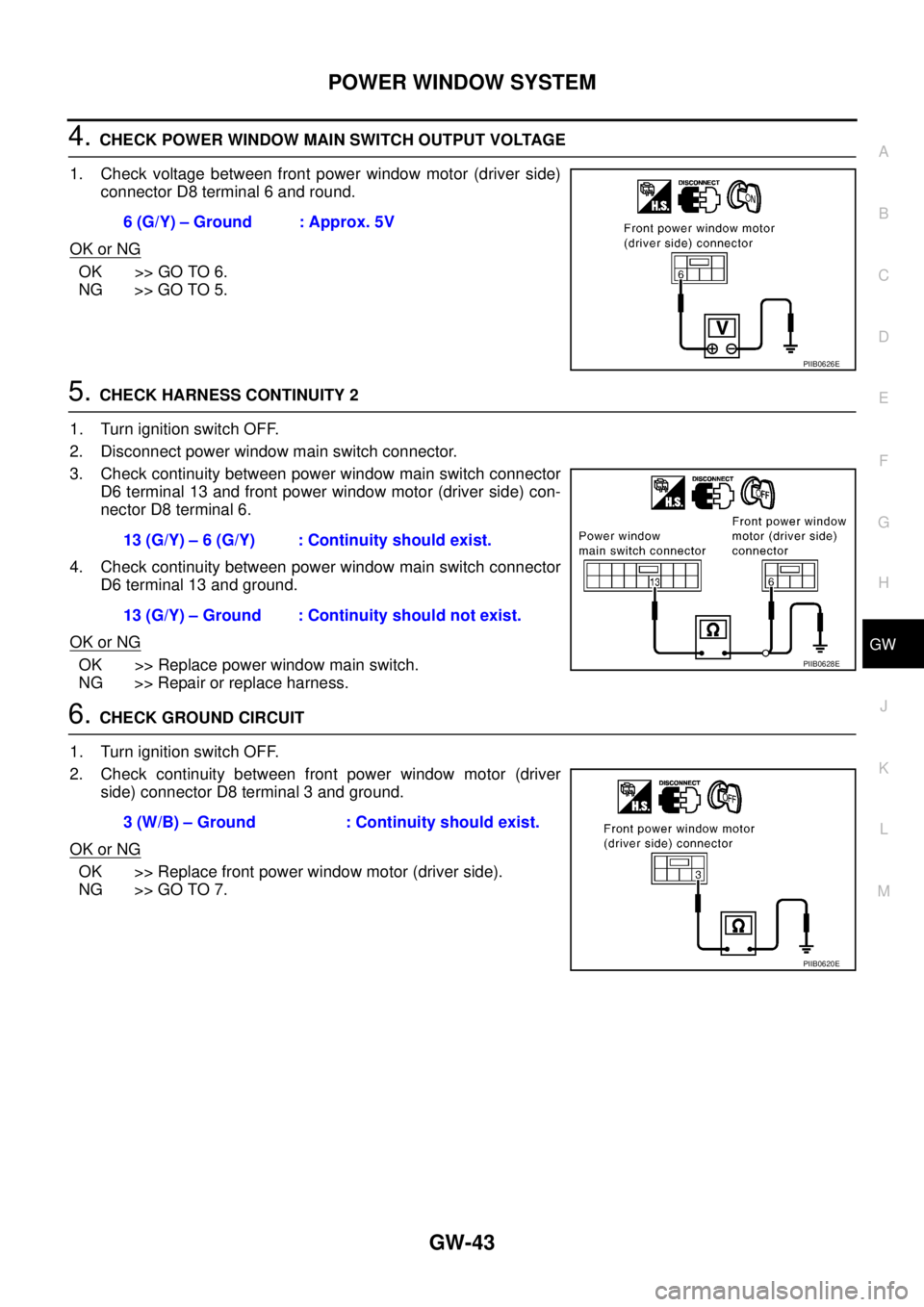
4. CHECK POWER WINDOW MAIN SWITCH OUTPUT VOLTAGE
1. Check voltage between front power window motor (driver side)
connector D8 terminal 6 and round.
OK or NG
OK >> GO TO 6.
NG >> GO TO 5.
5. CHECK HARNESS CONTINUITY 2
1. Turn ignition switch OFF.
2. Disconnect power window main switch connector.
3. Check continuity between power window main switch connector
D6 terminal 13 and front power window motor (driver side) con-
nector D8 terminal 6.
4. Check continuity between power window main switch connector
D6 terminal 13 and ground.
OK or NG
OK >> Replace power window main switch.
NG >> Repair or replace harness.
6. CHECK GROUND CIRCUIT
1. Turn ignition switch OFF.
2. Check continuity between front power window motor (driver
side) connector D8 terminal 3 and ground.
OK or NG
OK >> Replace front power window motor (driver side).
NG >> GO TO 7.6 (G/Y) – Ground : Approx. 5V
PIIB0626E
13 (G/Y) – 6 (G/Y) : Continuity should exist.
13 (G/Y) – Ground : Continuity should not exist.
PIIB0628E
3 (W/B) – Ground : Continuity should exist.
PIIB0620E
Page 2538 of 3502
GW-44
POWER WINDOW SYSTEM
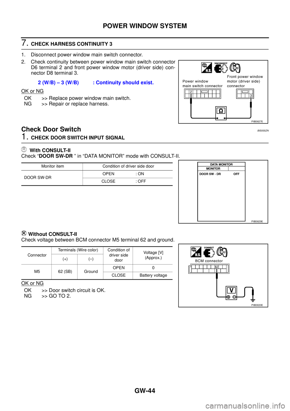
7. CHECK HARNESS CONTINUITY 3
1. Disconnect power window main switch connector.
2. Check continuity between power window main switch connector
D6 terminal 2 and front power window motor (driver side) con-
nector D8 terminal 3.
OK or NG
OK >> Replace power window main switch.
NG >> Repair or replace harness.
Check Door Switch BIS000ZN
1. CHECK DOOR SWITCH INPUT SIGNAL
With CONSULT-II
Check “DOOR SW-DR ” in “DATA MONITOR” mode with CONSULT-II.
Without CONSULT-II
Check voltage between BCM connector M5 terminal 62 and ground.
OK or NG
OK >> Door switch circuit is OK.
NG >> GO TO 2.2 (W/B) – 3 (W/B) : Continuity should exist.
PIIB0627E
Monitor item Condition of driver side door
DOOR SW-DROPEN : ON
CLOSE : OFF
PIIB0629E
ConnectorTerminals (Wire color) Condition of
driver side
doorVoltage [V]
(Approx.)
(+) (–)
M5 62 (SB) GroundOPEN 0
CLOSE Battery voltage
PIIB0630E
Page 2539 of 3502
POWER WINDOW SYSTEM
GW-45
C
D
E
F
G
H
J
K
L
MA
B
GW
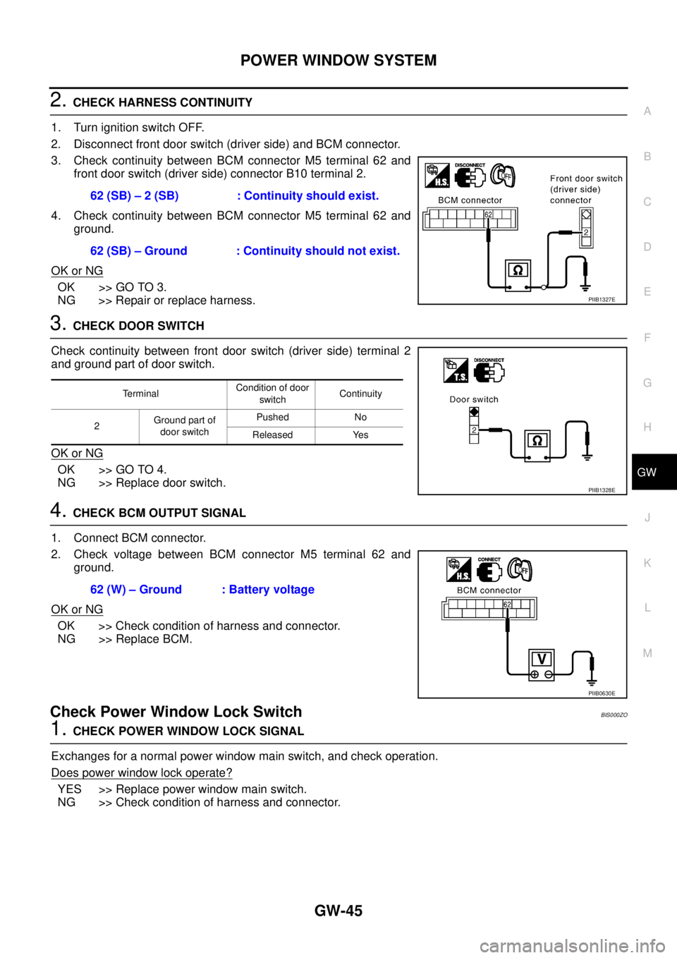
2. CHECK HARNESS CONTINUITY
1. Turn ignition switch OFF.
2. Disconnect front door switch (driver side) and BCM connector.
3. Check continuity between BCM connector M5 terminal 62 and
front door switch (driver side) connector B10 terminal 2.
4. Check continuity between BCM connector M5 terminal 62 and
ground.
OK or NG
OK >> GO TO 3.
NG >> Repair or replace harness.
3. CHECK DOOR SWITCH
Check continuity between front door switch (driver side) terminal 2
and ground part of door switch.
OK or NG
OK >> GO TO 4.
NG >> Replace door switch.
4. CHECK BCM OUTPUT SIGNAL
1. Connect BCM connector.
2. Check voltage between BCM connector M5 terminal 62 and
ground.
OK or NG
OK >> Check condition of harness and connector.
NG >> Replace BCM.
Check Power Window Lock Switch BIS000ZO
1. CHECK POWER WINDOW LOCK SIGNAL
Exchanges for a normal power window main switch, and check operation.
Does power window lock operate?
YES >> Replace power window main switch.
NG >> Check condition of harness and connector.62 (SB) – 2 (SB) : Continuity should exist.
62 (SB) – Ground : Continuity should not exist.
PIIB1327E
TerminalCondition of door
switchContinuity
2Ground part of
door switchPushed No
Released Yes
PIIB1328E
62 (W) – Ground : Battery voltage
PIIB0630E
Page 2540 of 3502
GW-46
FRONT DOOR GLASS AND REGULATOR
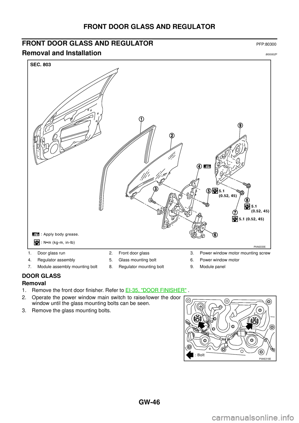
FRONT DOOR GLASS AND REGULATORPFP:80300
Removal and InstallationBIS000ZP
DOOR GLASS
Removal
1. Remove the front door finisher. Refer to EI-35, "DOOR FINISHER" .
2. Operate the power window main switch to raise/lower the door
window until the glass mounting bolts can be seen.
3. Remove the glass mounting bolts.
1. Door glass run 2. Front door glass 3. Power window motor mounting screw
4. Regulator assembly 5. Glass mounting bolt 6. Power window motor
7. Module assembly mounting bolt 8. Regulator mounting bolt 9. Module panel
PIIA6333E
PIIA6316E