NISSAN TEANA 2003 Service Manual
Manufacturer: NISSAN, Model Year: 2003, Model line: TEANA, Model: NISSAN TEANA 2003Pages: 3502, PDF Size: 74.56 MB
Page 2921 of 3502

INTERIOR ROOM LAMP
LT-233
C
D
E
F
G
H
I
J
L
MA
B
LT
CONSULT-II Functions (BCM)BKS001RB
CONSULT-II can display each diagnostic item using the diagnostic test mode shown following.
CONSULT-II BASIC OPERATION
Refer to GI-34, "CONSULT-II Start Procedure" .
WORK SUPPORT (INT LAMP)
Operation Procedure
1. Touch “INT LAMP” on “SELECT TEST ITEM” screen.
2. Touch “WORK SUPPORT” on “SELECT DIAG MODE” screen.
3. Touch “SET I/L D−UNLCK INTCON” on “SELECT WORK ITEM” screen.
4. Touch “START”.
5. Touch “CHANGE SETT”.
6. The setting will be changed and “CUSTOMIZING COMPLETED ” will be displayed.
7. Touch “END”.
Display Item List
Reference between “MODE” and “TIME” for “TURN ON/OFF”
DATA MONITOR (INT LAMP)
Operation Procedure
1. Touch “INT LAMP” on “SELECT TEST ITEM” screen.
2. Touch “DATA MONITOR” on “SELECT DIAG MODE” screen.
3. Touch either “ALL SIGNALS” or “SELECTION FROM MENU” on “SELECT MONITOR ITEM” screen.
4. When “SELECTION FROM MENU” is selected, touch individual items to be monitored. When “ALL SIG-
NALS” is selected, all the items will be monitored.
5. Touch “START”.
6. Touch “RECORD” while monitoring, then the status of the monitored item can be recorded. To stop
recording, touch “STOP”.
BCM diagnosis part Diagnosis mode Description
INT LAMPWORK SUPPORT Changes the setting for each function.
DATA MONITOR Displays BCM input data in real time.
ACTIVE TEST Operation of electrical loads can be checked by sending driving signal to them.
BATTERY SAVERWORK SUPPORT Changes the setting for each function.
DATA MONITOR Displays BCM input data in real time.
BCMSELF-DIAG RESULTS BCM performs self-diagnosis of CAN communication.
CAN DIAG SUPPORT MNTR The result of transmit/ receive diagnosis of CAN communication can be read.
Item Description CONSULT-II
SET I/L D−UNLCK INTCONThe 30 seconds glowing function the interior room lamps and the ignition keyhole
illumination can be selected.ON/OFF
ROOM LAMP ON TIM SETThe time to brighten illumination can be adjusted when the interior room lamps
and the ignition keyhole illumination is turned on.MODE 1 - 7
ROOM LAMP OFF TIM SETThe time to diminish illumination can be adjusted when the interior room lamps
and the ignition keyhole illumination is turned off.MODE 1 - 7
MODE 1 2 3 4 5 6 7
Time (sec.) 0.5 1 2 3 4 5 0
ALL SIGNALS Monitors all the items.
SELECTION FROM MENU Selects items and monitor them.
Page 2922 of 3502

LT-234
INTERIOR ROOM LAMP
Display Item List
NOTE:
1. Vehicle with Intelligent Key system displays this item.
2. Vehicle with remote keyless entry system displays this item.
ACTIVE TEST
Operation Procedure
1. Touch “INT LAMP” on “SELECT TEST ITEM” screen.
2. Touch “ACTIVE TEST” on “SELECT DIAG MODE” screen.
3. Touch item to be tested and check operation of the selected item.
4. During the operation check, touching “OFF” deactivates the operation.
Display Item List
WORK SUPPORT (BATTERY SAVER)
Operation procedure
1. Select “BATTERY SAVER” on “SELECT TEST ITEM” screen.
2. Select “WORK SUPPORT” on “SELECT DIAG MODE” screen.
3. Select “ROOM LAMP BAT SAV SET” on “SELECT WORK ITEM” screen.
4. Touch “START”.
5. Touch “MODE1” or “MODE2” (ROOM LAMP TIMER SET)
6. Touch “CHANGE SETT”.
7. The setting will be changed and “CUSTOMIZING COMPLETED” will be displayed.
8. Touch “END”.
Monitor item Contents
IGN ON SW “ON/OFF” Displays “IGN position (ON)/OFF, ACC position (OFF)” judged from the ignition switch signal.
KEY ON SW “ON/OFF” Displays “Key inserted (ON)/key removed (OFF)” status judged from the key switch signal.
DOOR SW - DR “ON/OFF”Displays status of the driver door as judged from the driver door switch signal. (Door is open:
ON/Door is closed: OFF)
DOOR SW - AS “ON/OFF”Displays “Door open (ON)/Door closed (OFF)” status, determined from passenger door
switch signal.
DOOR SW - RR “ON/OFF”Displays “Door open (ON)/Door closed (OFF)” status, determined from rear door switch RH
signal.
DOOR SW - RL “ON/OFF”Displays “Door open (ON)/Door closed (OFF) ” status, determined from rear door switch LH
signal.
LOCK STATUS “ON/OFF”Displays “Door unlocked (ON) /Door locked (OFF) status, determined from door unlock sen-
sor signal.
CDL LOCK SW “ON/OFF”Displays “Door locked (ON)/Door unlocked (OFF) status, determined from central door lock
switch LOCK signal.
CDL UNLOCK SW “ON/OFF”Displays “Door unlocked (OFF)” status, determined from central door lock switch UNLOCK
signal.
I − KEY LOCK
NOTE 1“ON/OFF” Displays “Locked (ON)/other (OFF)” status, determined from lock signal.
I − KEY UNLOCK
NOTE 1“ON/OFF” Displays “Unlocked (ON)/other (OFF)” status, determined from unlock signal.
KEYLESS LOCK
NOTE2“ON/OFF” Displays “Locked (ON)/other (OFF)” status, determined from lock signal.
KEYLESS UNLOCK
NOTE2“ON/OFF” Displays “Unlocked (ON)/other (OFF)” status, determined from unlock signal.
CONSULT-II screen
displayTest item Description
INT LAMPMap lamp, personal lamp and
ignition key hole illumination
operationMap lamp, personal lamp and ignition keyhole illumination is operated by
switching operation ON-OFF when map lamp switch and personal switch is in
DOOR position.
Page 2923 of 3502

INTERIOR ROOM LAMP
LT-235
C
D
E
F
G
H
I
J
L
MA
B
LT
Display Item List
DATA MONITOR (BATTERY SAVER)
Operation Procedure
1. Touch “BATTERY SAVER” on “SELECT TEST ITEM” screen.
2. Touch “DATA MONITOR” on “SELECT DIAG MODE” screen.
3. Touch either “ALL SIGNALS” or “SELECTION FROM MENU” on “SELECT MONITOR ITEM” screen.
4. When “ALL SIGNALS” is selected, all the items will be monitored. When “SELECTION FROM MENU” is
selected, touch individual items to be monitored.
5. Touch “START”.
6. Touch “RECORD” while monitoring, then the status of the monitored item can be recorded. To stop
recording, touch “STOP”.
Display Item List
NOTE:
1. Vehicle with Intelligent Key system displays this item.
2. Vehicle with remote keyless entry system displays this item.Item Description CONSULT-II
ROOM LAMP TIMER SET Interior room lamp battery saver timer setting can be changed.MODE 1: 30 min.
MODE 2: 60 min.
ROOM LAMP BAT SAV SETInterior room lamp battery saver control mode can be changed in this mode.
Select interior room lamp battery saver control mode between ON and OFF.ON/OFF
ALL SIGNALS Monitors all the items.
SELECTION FROM MENU Selects items and monitor them.
Monitor item Contents
IGN ON SW “ON/OFF”Displays “IGN position (ON)/OFF, ACC position (OFF)” judged from the ignition switch sig-
nal.
KEY ON SW “ON/OFF” Displays “Key inserted (ON)/key removed (OFF)” status judged from the key switch signal.
DOOR SW - DR “ON/OFF”Displays status of the driver door as judged from the driver door switch signal. (Door is open:
ON/Door is closed: OFF)
DOOR SW - AS “ON/OFF”Displays “Door open (ON)/Door closed (OFF)” status, determined from passenger door
switch signal.
DOOR SW - RR “ON/OFF”Displays “Door open (ON)/Door closed (OFF)” status, determined from rear door switch RH
signal.
DOOR SW - RL “ON/OFF”Displays “Door open (ON)/Door closed (OFF) ” status, determined from rear door switch LH
signal.
LOCK STATUS “ON/OFF”Displays “Door unlocked (ON)/Door locked (OFF) status, determined from door unlock sen-
sor signal.
CDL LOCK SW “ON/OFF”Displays “Door locked (ON)/Door unlocked (OFF) status, determined from central door lock
switch LOCK signal.
CDL UNLOCK SW “ON/OFF”Displays “Door unlocked (OFF)” status, determined from central door lock switch UNLOCK
signal.
I − KEY LOCK
NOTE 1“ON/OFF” Displays “Locked (ON)/other (OFF)” status, determined from lock signal.
I − KEY UNLOCK
NOTE 1“ON/OFF” Displays “Unlocked (ON)/other (OFF)” status, determined from unlock signal.
KEYLESS LOCK
NOTE2“ON/OFF” Displays “Locked (ON)/other (OFF)” status, determined from lock signal.
KEYLESS UNLOCK
NOTE2“ON/OFF” Displays “Unlocked (ON)/other (OFF)” status, determined from unlock signal.
Page 2924 of 3502
LT-236
INTERIOR ROOM LAMP
Interior Room Lamps Do Not IlluminateBKS002FV
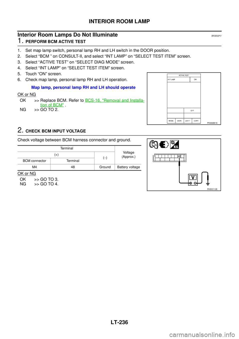
1. PERFORM BCM ACTIVE TEST
1. Set map lamp switch, personal lamp RH and LH switch in the DOOR position.
2. Select “BCM ” on CONSULT-II, and select “INT LAMP” on “SELECT TEST ITEM” screen.
3. Select “ACTIVE TEST” on “SELECT DIAG MODE” screen.
4. Select “INT LAMP” on “SELECT TEST ITEM” screen.
5. Touch “ON” screen.
6. Check map lamp, personal lamp RH and LH operation.
OK or NG
OK >> Replace BCM. Refer to BCS-16, "Removal and Installa-
tion of BCM" .
NG >> GO TO 2.
2. CHECK BCM INPUT VOLTAGE
Check voltage between BCM harness connector and ground.
OK or NG
OK >> GO TO 3.
NG >> GO TO 4.Map lamp, personal lamp RH and LH should operate
PKIA6881E
Terminal
Voltage
(Approx.) (+)
(−)
BCM connector Terminal
M4 48 Ground Battery voltage
PKID0112E
Page 2925 of 3502
INTERIOR ROOM LAMP
LT-237
C
D
E
F
G
H
I
J
L
MA
B
LT
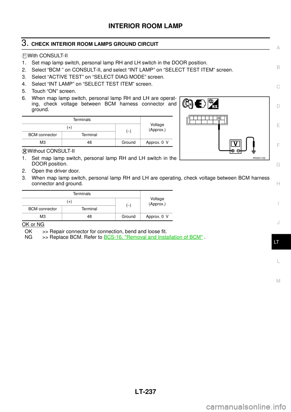
3. CHECK INTERIOR ROOM LAMPS GROUND CIRCUIT
With CONSULT-II
1. Set map lamp switch, personal lamp RH and LH switch in the DOOR position.
2. Select “BCM ” on CONSULT-II, and select “INT LAMP” on “SELECT TEST ITEM” screen.
3. Select “ACTIVE TEST” on “SELECT DIAG MODE” screen.
4. Select “INT LAMP” on “SELECT TEST ITEM” screen.
5. Touch “ON” screen.
6. When map lamp switch, personal lamp RH and LH are operat-
ing, check voltage between BCM harness connector and
ground.
Without CONSULT-II
1. Set map lamp switch, personal lamp RH and LH switch in the
DOOR position.
2. Open the driver door.
3. When map lamp switch, personal lamp RH and LH are operating, check voltage between BCM harness
connector and ground.
OK or NG
OK >> Repair connector for connection, bend and loose fit.
NG >> Replace BCM. Refer to BCS-16, "
Removal and Installation of BCM" .
Terminals
Voltage
(Approx.) (+)
(−)
BCM connector Terminal
M3 48 Ground Approx. 0 V
Terminals
Voltage
(Approx.) (+)
(−)
BCM connector Terminal
M3 48 Ground Approx. 0 V
PKID0112E
Page 2926 of 3502
LT-238
INTERIOR ROOM LAMP
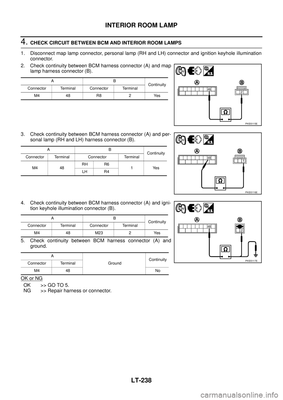
4. CHECK CIRCUIT BETWEEN BCM AND INTERIOR ROOM LAMPS
1. Disconnect map lamp connector, personal lamp (RH and LH) connector and ignition keyhole illumination
connector.
2. Check continuity between BCM harness connector (A) and map
lamp harness connector (B).
3. Check continuity between BCM harness connector (A) and per-
sonal lamp (RH and LH) harness connector (B).
4. Check continuity between BCM harness connector (A) and igni-
tion keyhole illumination connector (B).
5. Check continuity between BCM harness connector (A) and
ground.
OK or NG
OK >> GO TO 5.
NG >> Repair harness or connector.
AB
Continuity
Connector Terminal Connector Terminal
M4 48 R8 2 Yes
PKID0115E
AB
Continuity
Connector Terminal Connector Terminal
M4 48RH R6
1Yes
LH R4
PKID0116E
AB
Continuity
Connector Terminal Connector Terminal
M4 48 M23 2 Yes
A
GroundContinuity
Connector Terminal
M4 48 No
PKID0117E
Page 2927 of 3502
INTERIOR ROOM LAMP
LT-239
C
D
E
F
G
H
I
J
L
MA
B
LT
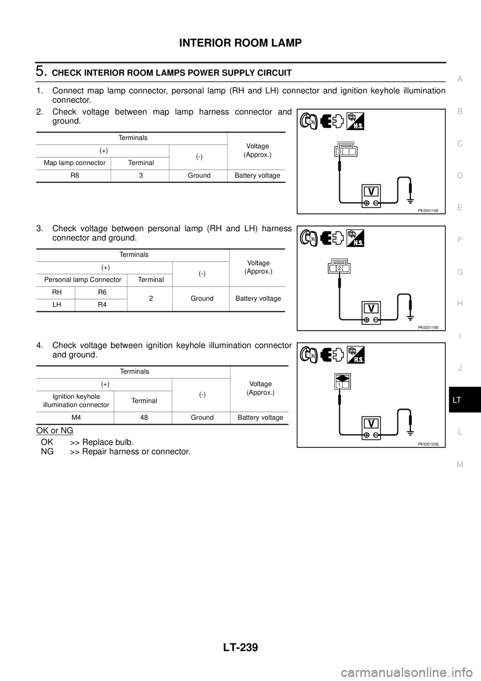
5. CHECK INTERIOR ROOM LAMPS POWER SUPPLY CIRCUIT
1. Connect map lamp connector, personal lamp (RH and LH) connector and ignition keyhole illumination
connector.
2. Check voltage between map lamp harness connector and
ground.
3. Check voltage between personal lamp (RH and LH) harness
connector and ground.
4. Check voltage between ignition keyhole illumination connector
and ground.
OK or NG
OK >> Replace bulb.
NG >> Repair harness or connector.
Terminals
Voltage
(Approx.) (+)
(-)
Map lamp connector Terminal
R8 3 Ground Battery voltage
PKID0114E
Terminals
Voltage
(Approx.) (+)
(-)
Personal lamp Connector Terminal
RH R6
2 Ground Battery voltage
LH R4
PKID0119E
Terminals
Voltage
(Approx.) (+)
(-)
Ignition keyhole
illumination connectorTerminal
M4 48 Ground Battery voltage
PKID0120E
Page 2928 of 3502
LT-240
INTERIOR ROOM LAMP
Interior Room Lamps Illuminate But Timer Does Not OperateBKS002FW
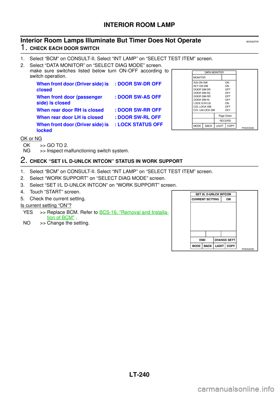
1. CHECK EACH DOOR SWITCH
1. Select “BCM” on CONSULT-II. Select “INT LAMP” on “SELECT TEST ITEM” screen.
2. Select “DATA MONITOR” on “SELECT DIAG MODE” screen.
make sure switches listed below turn ON-OFF according to
switch operation.
OK or NG
OK >> GO TO 2.
NG >> Inspect malfunctioning switch system.
2. CHECK “SET I/L D-UNLCK INTCON” STATUS IN WORK SUPPORT
1. Select “BCM” on CONSULT-II. Select “INT LAMP” on “SELECT TEST ITEM” screen.
2. Select “WORK SUPPORT” on “SELECT DIAG MODE” screen.
3. Select “SET I/L D-UNLCK INTCON” on “WORK SUPPORT” screen.
4. Touch “START” screen.
5. Check the current setting.
Is current setting
“ON”?
YES >> Replace BCM. Refer to BCS-16, "Removal and Installa-
tion of BCM" .
NO >> Change the setting.When front door (Driver side) is
closed: DOOR SW-DR OFF
When front door (passenger
side) is closed: DOOR SW-AS OFF
When rear door RH is closed : DOOR SW-RR OFF
When rear door LH is closed : DOOR SW-RL OFF
When front door (Driver side) is
locked: LOCK STATUS OFF
PKID0303E
PKID0203E
Page 2929 of 3502
INTERIOR ROOM LAMP
LT-241
C
D
E
F
G
H
I
J
L
MA
B
LT
Bulb ReplacementBKS0040I
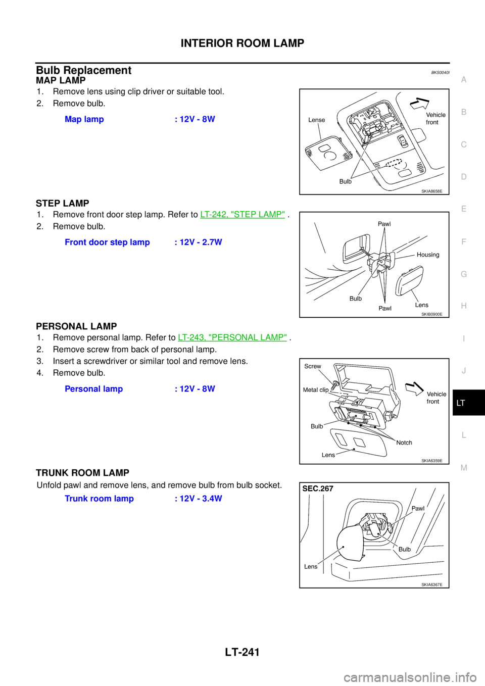
MAP LAMP
1. Remove lens using clip driver or suitable tool.
2. Remove bulb.
STEP LAMP
1. Remove front door step lamp. Refer to LT- 2 4 2 , "STEP LAMP" .
2. Remove bulb.
PERSONAL LAMP
1. Remove personal lamp. Refer to LT- 2 4 3 , "PERSONAL LAMP" .
2. Remove screw from back of personal lamp.
3. Insert a screwdriver or similar tool and remove lens.
4. Remove bulb.
TRUNK ROOM LAMP
Unfold pawl and remove lens, and remove bulb from bulb socket.Map lamp : 12V - 8W
SKIA8658E
Front door step lamp : 12V - 2.7W
SKIB0900E
Personal lamp : 12V - 8W
SKIA6359E
Trunk room lamp : 12V - 3.4W
SKIA6367E
Page 2930 of 3502
LT-242
INTERIOR ROOM LAMP
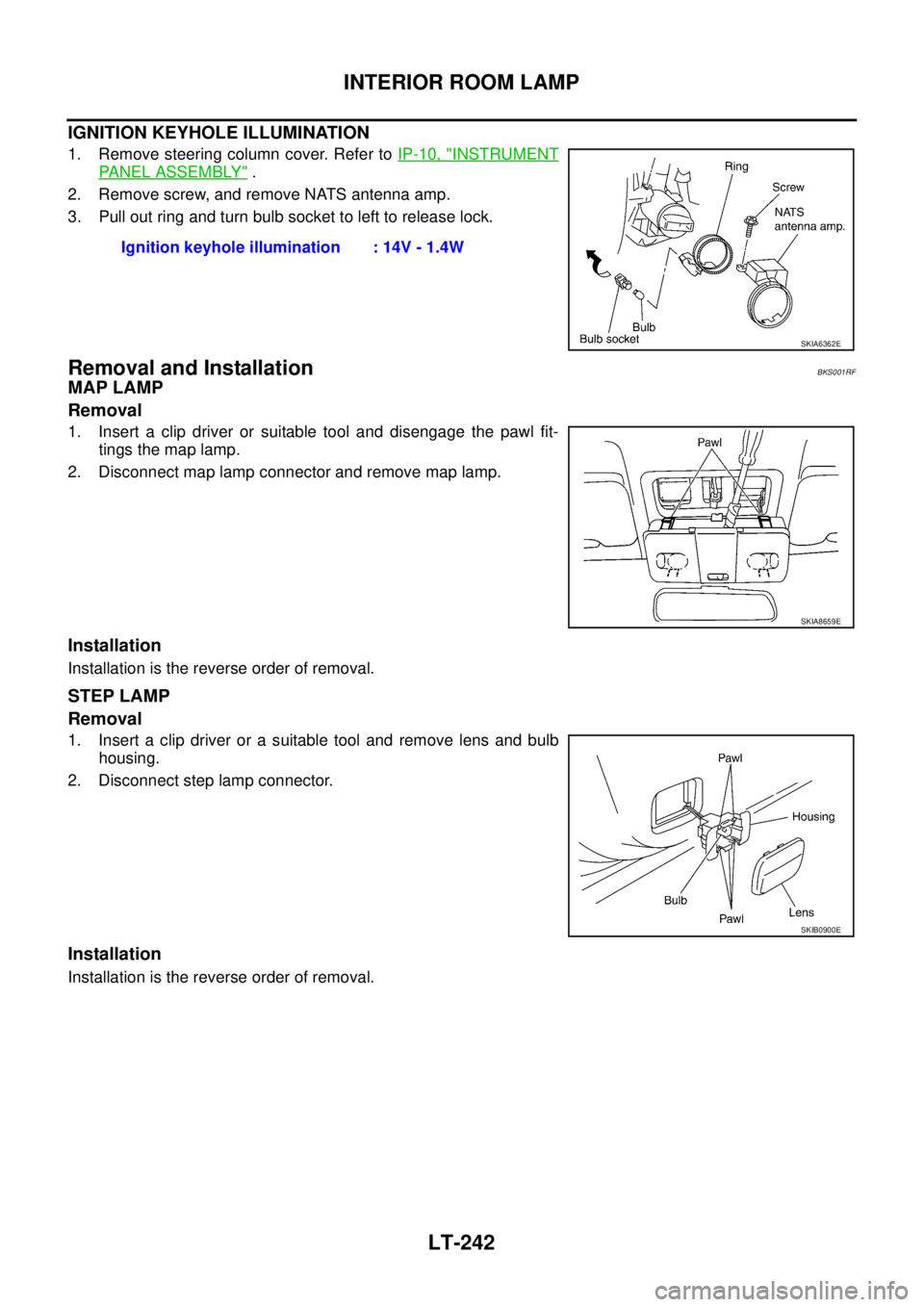
IGNITION KEYHOLE ILLUMINATION
1. Remove steering column cover. Refer to IP-10, "INSTRUMENT
PANEL ASSEMBLY" .
2. Remove screw, and remove NATS antenna amp.
3. Pull out ring and turn bulb socket to left to release lock.
Removal and InstallationBKS001RF
MAP LAMP
Removal
1. Insert a clip driver or suitable tool and disengage the pawl fit-
tings the map lamp.
2. Disconnect map lamp connector and remove map lamp.
Installation
Installation is the reverse order of removal.
STEP LAMP
Removal
1. Insert a clip driver or a suitable tool and remove lens and bulb
housing.
2. Disconnect step lamp connector.
Installation
Installation is the reverse order of removal.Ignition keyhole illumination : 14V - 1.4W
SKIA6362E
SKIA8659E
SKIB0900E