sport mode NISSAN TEANA 2008 User Guide
[x] Cancel search | Manufacturer: NISSAN, Model Year: 2008, Model line: TEANA, Model: NISSAN TEANA 2008Pages: 5121, PDF Size: 69.03 MB
Page 4476 of 5121
TM-3
C
E
F
G
H
I
J
K
L
MA
B
TM
N
O
P Component Inspection [Pressure Control Sole-
noid Valve B (Secondary Pressure Solenoid
Valve)] .....................................................................
84
P1701 TRANSMISSION CONTROL MODULE
(POWER SUPPLY) .............................................
85
Description ..............................................................85
DTC Logic ...............................................................85
Diagnosis Procedure ...............................................85
P1705 THROTTLE POSITION SENSOR ...........88
Description ..............................................................88
DTC Logic ...............................................................88
Diagnosis Procedure ...............................................88
P1722 ESTM VEHICLE SPEED SIGNAL ..........89
Description ..............................................................89
DTC Logic ...............................................................89
Diagnosis Procedure ...............................................89
P1723 CVT SPEED SENSOR FUNCTION ........91
Description ..............................................................91
DTC Logic ...............................................................91
Diagnosis Procedure ...............................................91
P1726 ELECTRIC THROTTLE CONTROL
SYSTEM .............................................................
93
Description ..............................................................93
DTC Logic ...............................................................93
Diagnosis Procedure ...............................................93
P1740 LOCK-UP SELECT SOLENOID
VALVE ................................................................
94
Description ..............................................................94
DTC Logic ...............................................................94
Diagnosis Procedure ...............................................94
Component Inspection (Lock-up Select Solenoid
Valve) ......................................................................
95
P1745 LINE PRESSURE CONTROL .................96
Description ..............................................................96
DTC Logic ...............................................................96
Diagnosis Procedure ...............................................96
P1777 STEP MOTOR .........................................97
Description ..............................................................97
DTC Logic ...............................................................97
Diagnosis Procedure ...............................................97
Component Inspection (Step Motor) .......................98
P1778 STEP MOTOR - FUNCTION .................100
Description ............................................................100
DTC Logic .............................................................100
Diagnosis Procedure .............................................100
SHIFT POSITION INDICATOR CIRCUIT .........102
Description ............................................................102
Component Function Check ..................................102
Diagnosis Procedure .............................................102
SHIFT LOCK SYSTEM .....................................103
Description .............................................................103
Wiring Diagram - CVT SHIFT LOCK SYSTEM - ...103
Component Function Check ..................................105
Diagnosis Procedure .............................................106
Component Inspection (Stop Lamp Switch) ..........107
SPORT MODE SWITCH .................................108
Description .............................................................108
Component Function Check ..................................108
Diagnosis Procedure .............................................108
ECU DIAGNOSIS .......................................111
TCM .................................................................111
Reference Value ....................................................111
Wiring Diagram - CVT CONTROL SYSTEM - .......116
Fail-safe .................................................................120
DTC Inspection Priority Chart ................................121
DTC Index .............................................................121
SYMPTOM DIAGNOSIS ............................123
SYSTEM SYMPTOM .......................................123
Symptom Table .....................................................123
PRECAUTION ............................................135
PRECAUTIONS ...............................................135
Precaution for Supplemental Restraint System
(SRS) "AIR BAG" and "SEAT BELT PRE-TEN-
SIONER" ...............................................................
135
Precaution Necessary for Steering Wheel Rota-
tion after Battery Disconnect .................................
135
Precaution for Procedure without Cowl Top Cover ..136
Precaution for On Board Diagnosis (OBD) System
of CVT and Engine ................................................
136
Precaution for TCM and CVT Assembly Replace-
ment .......................................................................
136
Removal and Installation Procedure for CVT Unit
Connector ..............................................................
136
Precaution .............................................................138
Service Notice or Precaution .................................138
ATFTEMP COUNT Conversion Table ...................139
PREPARATION .........................................140
PREPARATION ...............................................140
Special Service Tools ............................................140
Commercial Service Tools .....................................140
ON-VEHICLE MAINTENANCE ..................142
CVT FLUID ......................................................142
Inspection ..............................................................142
Changing ...............................................................143
STALL TEST ...................................................144
Inspection and Judgment ......................................144
LINE PRESSURE TEST ..................................146
Inspection and Judgment ......................................146
Page 4479 of 5121
TM-6
P0778 PRESSURE CONTROL SOLENOID B
ELECTRICAL (SEC PRESSURE SOLENOID
VALVE) ............................................................
240
Description .............................................................240
DTC Logic ..............................................................240
Diagnosis Procedure .............................................240
Component Inspection [Pressure Control Sole-
noid Valve B (Secondary Pressure Solenoid
Valve)] ...................................................................
241
P0840 TRANSMISSION FLUID PRESSURE
SENSOR A (SEC PRESSURE SENSOR) .......
242
Description .............................................................242
DTC Logic ..............................................................242
Diagnosis Procedure .............................................242
P0841 PRESSURE SENSOR FUNCTION ......245
Description .............................................................245
DTC Logic ..............................................................245
Diagnosis Procedure .............................................245
Component Inspection [Pressure Control Sole-
noid Valve A (Line Pressure Solenoid Valve)] .......
246
Component Inspection [Pressure Control Sole-
noid Valve B (Secondary Pressure Solenoid
Valve)] ...................................................................
246
P0868 SECONDARY PRESSURE DOWN ......247
Description .............................................................247
DTC Logic ..............................................................247
Diagnosis Procedure .............................................247
Component Inspection [Pressure Control Sole-
noid Valve A (Line Pressure Solenoid Valve)] .......
248
Component Inspection [Pressure Control Sole-
noid Valve B (Secondary Pressure Solenoid
Valve)] ...................................................................
248
P1701 TRANSMISSION CONTROL MODULE
(POWER SUPPLY) ..........................................
249
Description .............................................................249
DTC Logic ..............................................................249
Diagnosis Procedure .............................................249
P1705 THROTTLE POSITION SENSOR ........252
Description .............................................................252
DTC Logic ..............................................................252
Diagnosis Procedure .............................................252
P1722 ESTM VEHICLE SPEED SIGNAL ........253
Description .............................................................253
DTC Logic ..............................................................253
Diagnosis Procedure .............................................253
P1723 CVT SPEED SENSOR FUNCTION ......255
Description .............................................................255
DTC Logic ..............................................................255
Diagnosis Procedure .............................................255
P1726 ELECTRIC THROTTLE CONTROL
SYSTEM ...........................................................
257
Description .............................................................257
DTC Logic .............................................................257
Diagnosis Procedure .............................................257
P1740 LOCK-UP SELECT SOLENOID
VALVE ..............................................................
258
Description ............................................................258
DTC Logic .............................................................258
Diagnosis Procedure .............................................258
Component Inspection (Lock-up Select Solenoid
Valve) ....................................................................
259
P1745 LINE PRESSURE CONTROL ...............260
Description ............................................................260
DTC Logic .............................................................260
Diagnosis Procedure .............................................260
P1777 STEP MOTOR .......................................261
Description ............................................................261
DTC Logic .............................................................261
Diagnosis Procedure .............................................261
Component Inspection (Step Motor) .....................263
P1778 STEP MOTOR - FUNCTION .................264
Description ............................................................264
DTC Logic .............................................................264
Diagnosis Procedure .............................................264
SHIFT POSITION INDICATOR CIRCUIT .........266
Description ............................................................266
Component Function Check .................................266
Diagnosis Procedure .............................................266
SHIFT LOCK SYSTEM .....................................267
Description ............................................................267
Wiring Diagram - CVT SHIFT LOCK SYSTEM - ...267
Component Function Check .................................269
Diagnosis Procedure .............................................270
Component Inspection (Stop Lamp Switch) ..........271
SPORT MODE SWITCH ...................................272
Description ............................................................272
Component Function Check .................................272
Diagnosis Procedure .............................................272
ECU DIAGNOSIS ......................................275
TCM ..................................................................275
Reference Value ...................................................275
Wiring Diagram - CVT CONTROL SYSTEM - ......279
Fail-safe ................................................................283
DTC Inspection Priority Chart ...............................284
DTC Index .............................................................284
SYMPTOM DIAGNOSIS ...........................286
SYSTEM SYMPTOM ........................................286
Symptom Table .....................................................286
PRECAUTION ...........................................297
PRECAUTIONS ................................................297
Page 4487 of 5121
TM-14
< FUNCTION DIAGNOSIS >[CVT: RE0F09B]
CVT SYSTEM
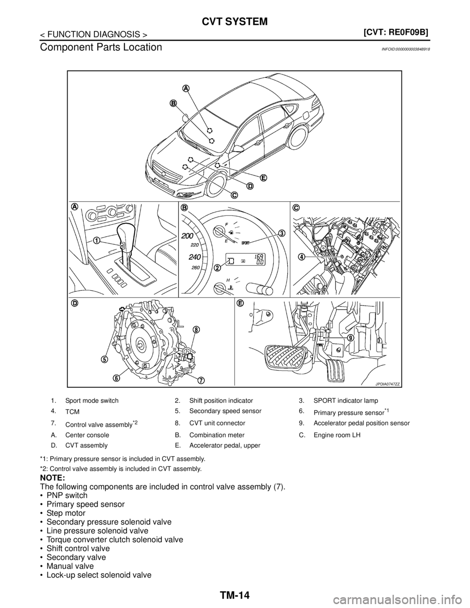
Component Parts Location
INFOID:0000000003848918
*1: Primary pressure sensor is included in CVT assembly.
*2: Control valve assembly is included in CVT assembly.
NOTE:
The following components are included in control valve assembly (7).
PNP switch
Primary speed sensor
Step motor
Secondary pressure solenoid valve
Line pressure solenoid valve
Torque converter clutch solenoid valve
Shift control valve
Secondary valve
Manual valve
Lock-up select solenoid valve
1. Sport mode switch 2. Shift position indicator 3. SPORT indicator lamp
4.
TCM5. Secondary speed sensor 6.
Primary pressure sensor
*1
7.
Control valve assembly*28. CVT unit connector 9. Accelerator pedal position sensor
A. Center console B. Combination meter C. Engine room LH
D. CVT assembly E. Accelerator pedal, upper
JPDIA0747ZZ
Page 4491 of 5121
TM-18
< FUNCTION DIAGNOSIS >[CVT: RE0F09B]
MECHANICAL SYSTEM
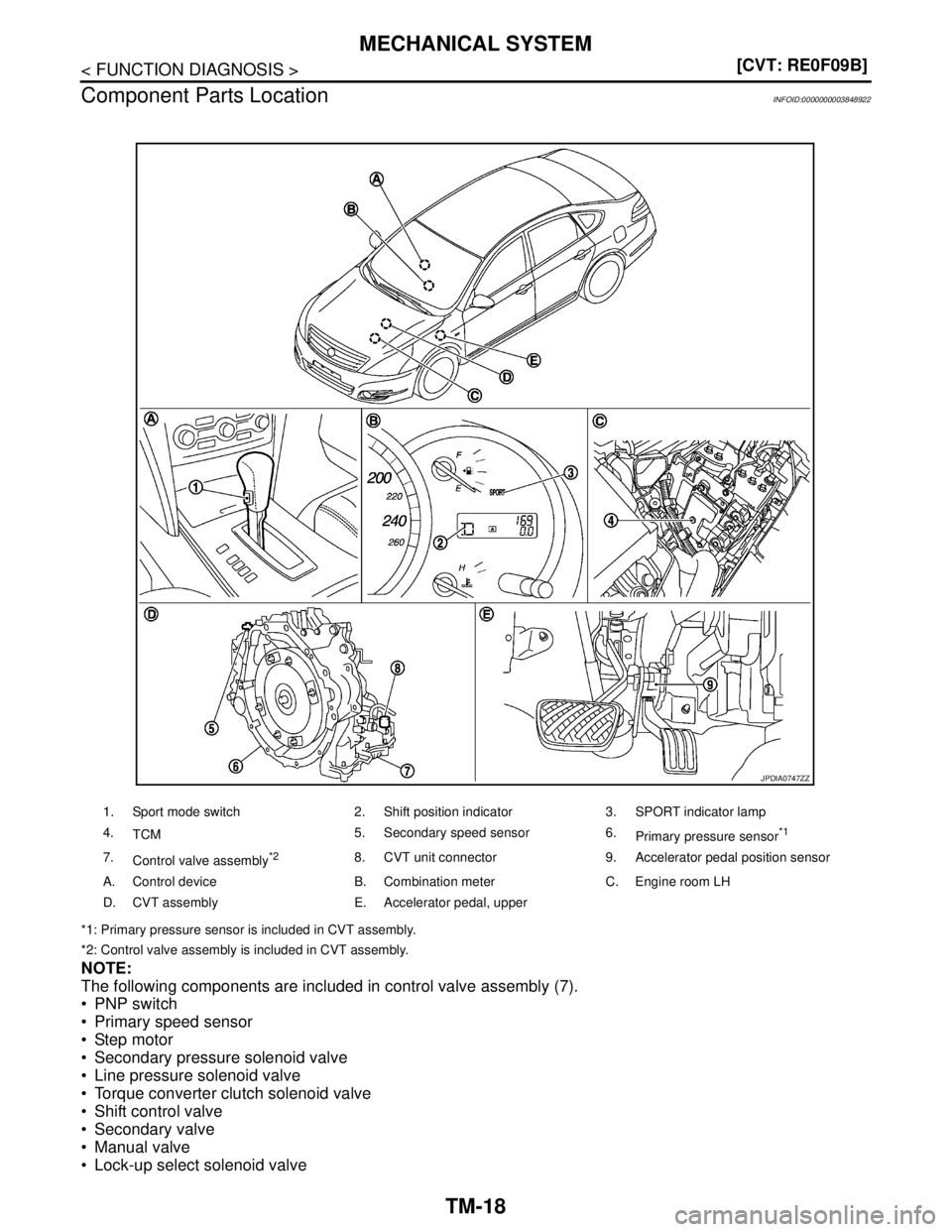
Component Parts Location
INFOID:0000000003848922
*1: Primary pressure sensor is included in CVT assembly.
*2: Control valve assembly is included in CVT assembly.
NOTE:
The following components are included in control valve assembly (7).
PNP switch
Primary speed sensor
Step motor
Secondary pressure solenoid valve
Line pressure solenoid valve
Torque converter clutch solenoid valve
Shift control valve
Secondary valve
Manual valve
Lock-up select solenoid valve
1. Sport mode switch 2. Shift position indicator 3. SPORT indicator lamp
4.
TCM5. Secondary speed sensor 6.
Primary pressure sensor
*1
7.
Control valve assembly*28. CVT unit connector 9. Accelerator pedal position sensor
A. Control device B. Combination meter C. Engine room LH
D. CVT assembly E. Accelerator pedal, upper
JPDIA0747ZZ
Page 4494 of 5121
HYDRAULIC CONTROL SYSTEM
TM-21
< FUNCTION DIAGNOSIS >[CVT: RE0F09B]
C
E
F
G
H
I
J
K
L
MA
B
TM
N
O
P Normal Control
Optimize the line pressure and secondary pressure, depending on driving conditions, on the basis of the throt-
tle position, the engine speed, the primary pulley (input) revolution speed, the secondary pulley (output) revo-
lution speed, the brake signal, the PNP switch signal, the lock-up signal, the voltage, the target gear ratio, the
fluid temperature, and the fluid pressure.
Feedback Control
For the normal fluid control and the select fluid control, secondary pressure is detected for feedback control by
using a secondary pressure sensor to set a high-precision secondary pressure.
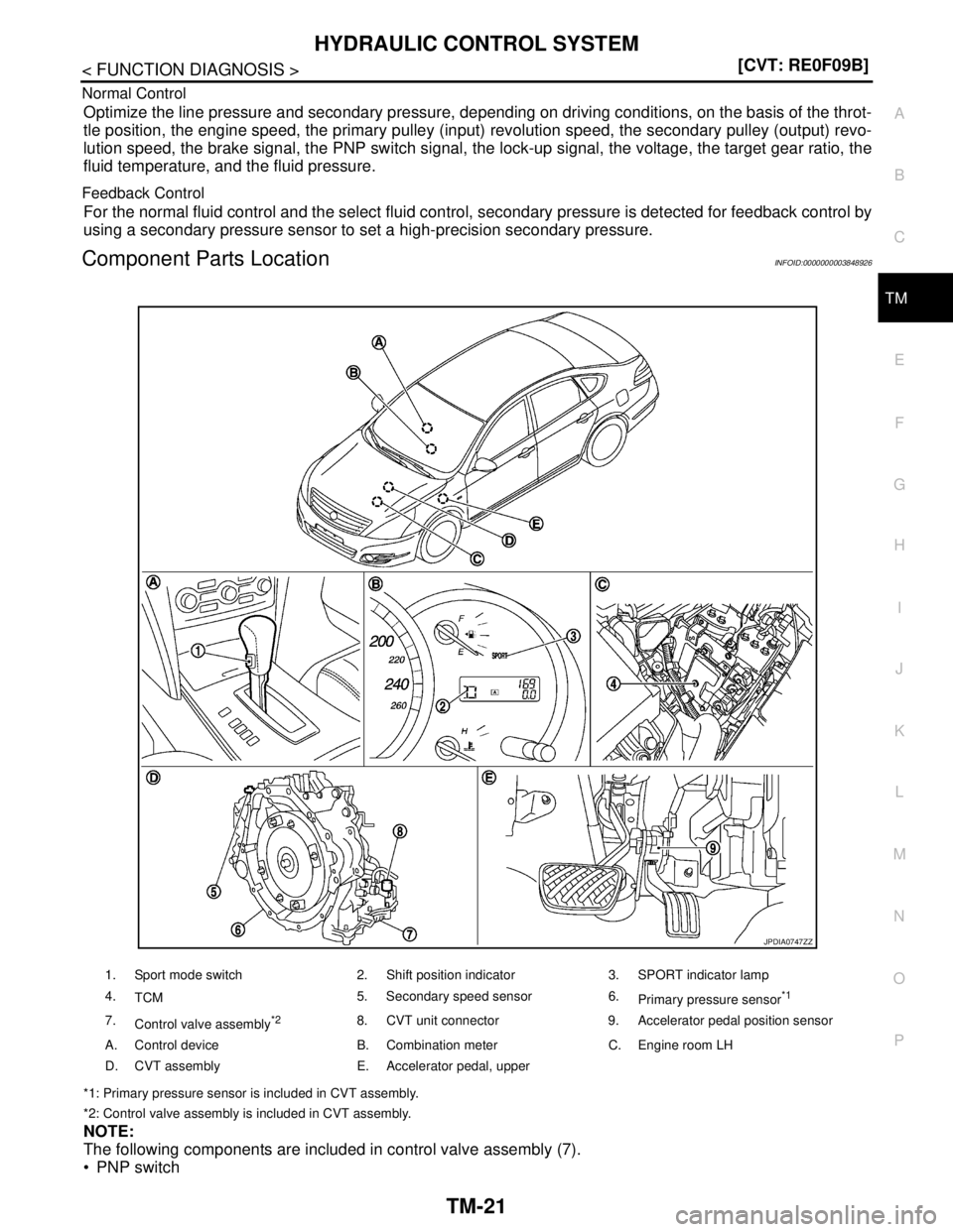
Component Parts LocationINFOID:0000000003848926
*1: Primary pressure sensor is included in CVT assembly.
*2: Control valve assembly is included in CVT assembly.
NOTE:
The following components are included in control valve assembly (7).
PNP switch
1. Sport mode switch 2. Shift position indicator 3. SPORT indicator lamp
4.
TCM5. Secondary speed sensor 6.
Primary pressure sensor
*1
7.
Control valve assembly*28. CVT unit connector 9. Accelerator pedal position sensor
A. Control device B. Combination meter C. Engine room LH
D. CVT assembly E. Accelerator pedal, upper
JPDIA0747ZZ
Page 4496 of 5121
CONTROL SYSTEM
TM-23
< FUNCTION DIAGNOSIS >[CVT: RE0F09B]
C
E
F
G
H
I
J
K
L
MA
B
TM
N
O
P
CONTROL SYSTEM
System DiagramINFOID:0000000003848928
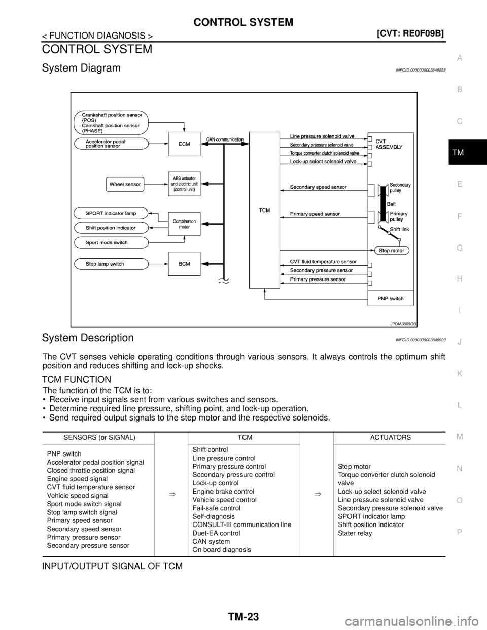
System DescriptionINFOID:0000000003848929
The CVT senses vehicle operating conditions through various sensors. It always controls the optimum shift
position and reduces shifting and lock-up shocks.
TCM FUNCTION
The function of the TCM is to:
Receive input signals sent from various switches and sensors.
Determine required line pressure, shifting point, and lock-up operation.
Send required output signals to the step motor and the respective solenoids.
INPUT/OUTPUT SIGNAL OF TCM
JPDIA0809GB
SENSORS (or SIGNAL)
⇒TCM
⇒ACTUATORS
PNP switch
Accelerator pedal position signal
Closed throttle position signal
Engine speed signal
CVT fluid temperature sensor
Vehicle speed signal
Sport mode switch signal
Stop lamp switch signal
Primary speed sensor
Secondary speed sensor
Primary pressure sensor
Secondary pressure sensorShift control
Line pressure control
Primary pressure control
Secondary pressure control
Lock-up control
Engine brake control
Vehicle speed control
Fail-safe control
Self-diagnosis
CONSULT-III communication line
Duet-EA control
CAN system
On board diagnosisStep motor
Torque converter clutch solenoid
valve
Lock-up select solenoid valve
Line pressure solenoid valve
Secondary pressure solenoid valve
SPORT indicator lamp
Shift position indicator
Stater relay
Page 4497 of 5121
TM-24
< FUNCTION DIAGNOSIS >[CVT: RE0F09B]
CONTROL SYSTEM
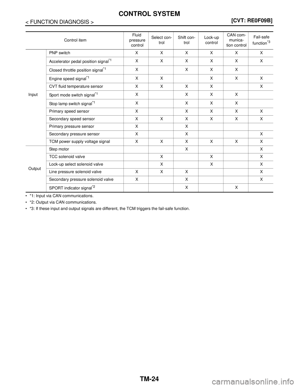
*1: Input via CAN communications.
*2: Output via CAN communications.
*3: If these input and output signals are different, the TCM triggers the fail-safe function.Control itemFluid
pressure
controlSelect con-
trolShift con-
trolLock-up
controlCAN com-
munica-
tion controlFail-safe
function
*3
InputPNP switch XXXXXX
Accelerator pedal position signal
*1XXXXXX
Closed throttle position signal
*1X XXX
Engine speed signal
*1XX XXX
CVT fluid temperature sensor X X X X X
Sport mode switch signal
*1X XXX
Stop lamp switch signal
*1X XXX
Primary speed sensor X XXXX
Secondary speed sensor XXXXXX
Primary pressure sensor X X
Secondary pressure sensor X X X
TCM power supply voltage signal XXXXXX
OutputSte p m ot or X X
TCC solenoid valve X X X
Lock-up select solenoid valve X X X
Line pressure solenoid valve X X X X
Secondary pressure solenoid valve X X X
SPORT indicator signal
*2XX
Page 4498 of 5121
CONTROL SYSTEM
TM-25
< FUNCTION DIAGNOSIS >[CVT: RE0F09B]
C
E
F
G
H
I
J
K
L
MA
B
TM
N
O
P
Component Parts LocationINFOID:0000000003848930
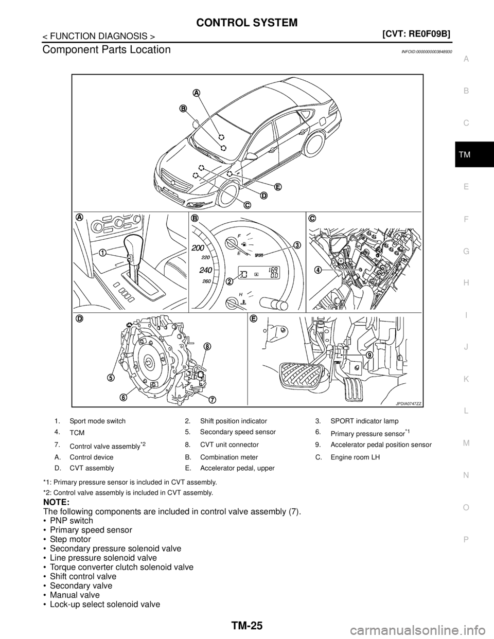
*1: Primary pressure sensor is included in CVT assembly.
*2: Control valve assembly is included in CVT assembly.
NOTE:
The following components are included in control valve assembly (7).
PNP switch
Primary speed sensor
Step motor
Secondary pressure solenoid valve
Line pressure solenoid valve
Torque converter clutch solenoid valve
Shift control valve
Secondary valve
Manual valve
Lock-up select solenoid valve
1. Sport mode switch 2. Shift position indicator 3. SPORT indicator lamp
4.
TCM5. Secondary speed sensor 6.
Primary pressure sensor
*1
7.
Control valve assembly*28. CVT unit connector 9. Accelerator pedal position sensor
A. Control device B. Combination meter C. Engine room LH
D. CVT assembly E. Accelerator pedal, upper
JPDIA0747ZZ
Page 4501 of 5121
TM-28
< FUNCTION DIAGNOSIS >[CVT: RE0F09B]
LOCK-UP AND SELECT CONTROL SYSTEM
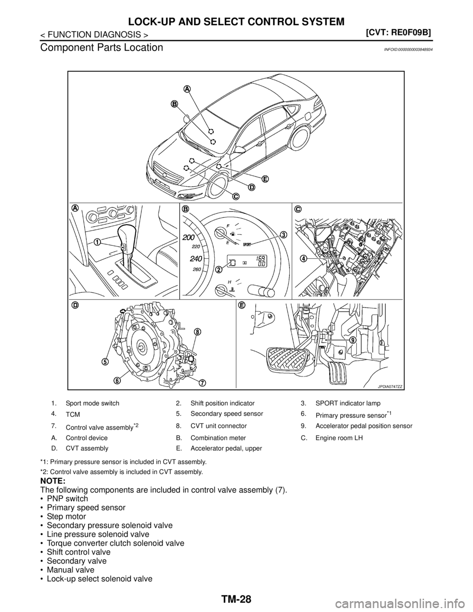
Component Parts Location
INFOID:0000000003848934
*1: Primary pressure sensor is included in CVT assembly.
*2: Control valve assembly is included in CVT assembly.
NOTE:
The following components are included in control valve assembly (7).
PNP switch
Primary speed sensor
Step motor
Secondary pressure solenoid valve
Line pressure solenoid valve
Torque converter clutch solenoid valve
Shift control valve
Secondary valve
Manual valve
Lock-up select solenoid valve
1. Sport mode switch 2. Shift position indicator 3. SPORT indicator lamp
4.
TCM5. Secondary speed sensor 6.
Primary pressure sensor
*1
7.
Control valve assembly*28. CVT unit connector 9. Accelerator pedal position sensor
A. Control device B. Combination meter C. Engine room LH
D. CVT assembly E. Accelerator pedal, upper
JPDIA0747ZZ
Page 4503 of 5121
TM-30
< FUNCTION DIAGNOSIS >[CVT: RE0F09B]
SHIFT CONTROL SYSTEM
SHIFT CONTROL SYSTEM
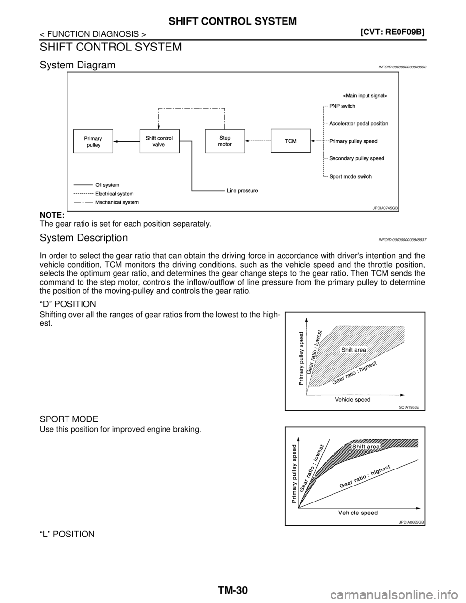
System DiagramINFOID:0000000003848936
NOTE:
The gear ratio is set for each position separately.
System DescriptionINFOID:0000000003848937
In order to select the gear ratio that can obtain the driving force in accordance with driver's intention and the
vehicle condition, TCM monitors the driving conditions, such as the vehicle speed and the throttle position,
selects the optimum gear ratio, and determines the gear change steps to the gear ratio. Then TCM sends the
command to the step motor, controls the inflow/outflow of line pressure from the primary pulley to determine
the position of the moving-pulley and controls the gear ratio.
“D” POSITION
Shifting over all the ranges of gear ratios from the lowest to the high-
est.
SPORT MODE
Use this position for improved engine braking.
“L” POSITION
JPDIA0745GB
SCIA1953E
JPDIA0685GB