NISSAN TEANA 2008 Service Manual
Manufacturer: NISSAN, Model Year: 2008, Model line: TEANA, Model: NISSAN TEANA 2008Pages: 5121, PDF Size: 69.03 MB
Page 2021 of 5121
EM-146
< SERVICE DATA AND SPECIFICATIONS (SDS)
SERVICE DATA AND SPECIFICATIONS (SDS)
Unit: mm (in)
*: Total indicator reading
Main BearingINFOID:0000000003802308
MAIN BEARING
Engine VQ25DE VQ35DE
Main journal diameter. “Dm”
gradeStandardGrade No. A
Grade No. B
Grade No. C
Grade No. D
Grade No. E
Grade No. F
Grade No. G
Grade No. H
Grade No. J
Grade No. K
Grade No. L
Grade No. M
Grade No. N
Grade No. P
Grade No. R
Grade No. S
Grade No. T
Grade No. U
Grade No. V
Grade No. W
Grade No. X
Grade No. Y
Grade No. 4
Grade No. 759.975 - 59.974 (2.3612 - 2.3612)
59.974 - 59.973 (2.3612 - 2.3611)
59.973 - 59.972 (2.3611 - 2.3611)
59.972 - 59.971 (2.3611 - 2.3611)
59.971 - 59.970 (2.3611 - 2.3610)
59.970 - 59.969 (2.3610 - 2.3610)
59.969 - 59.968 (2.3610 - 2.3609)
59.968 - 59.967 (2.3609 - 2.3609)
59.967 - 59.966 (2.3609 - 2.3609)
59.966 - 59.965 (2.3609 - 2.3608)
59.965 - 59.964 (2.3608 - 2.3608)
59.964 - 59.963 (2.3608 - 2.3607)
59.963 - 59.962 (2.3607 - 2.3607)
59.962 - 59.961 (2.3607 - 2.3607)
59.961 - 59.960 (2.3607 - 2.3606)
59.960 - 59.959 (2.3606 - 2.3606)
59.959 - 59.958 (2.3606 - 2.3605)
59.958 - 59.957 (2.3605 - 2.3605)
59.957 - 59.956 (2.3605 - 2.3605)
59.956 - 59.955 (2.3605 - 2.3604)
59.955 - 59.954 (2.3604 - 2.3604)
59.954 - 59.953 (2.3604 - 2.3603)
59.953 - 59.952 (2.3603 - 2.3603)
59.952 - 59.951 (2.3603 - 2.3603)
Pin journal diameter. “Dp” grade StandardGrade No. 0 44.968 - 44.974 (1.7704 - 1.7706) 51.968 - 51.974 (2.0460 - 2.0462)
Grade No. 1 44.962 - 44.968 (1.7702 - 1.7704) 51.962 - 51.968 (2.0457 - 2.0460)
Grade No. 2 44.956 - 44.962 (1.7699 - 1.7702) 51.956 - 51.962 (2.0445 - 2.0457)
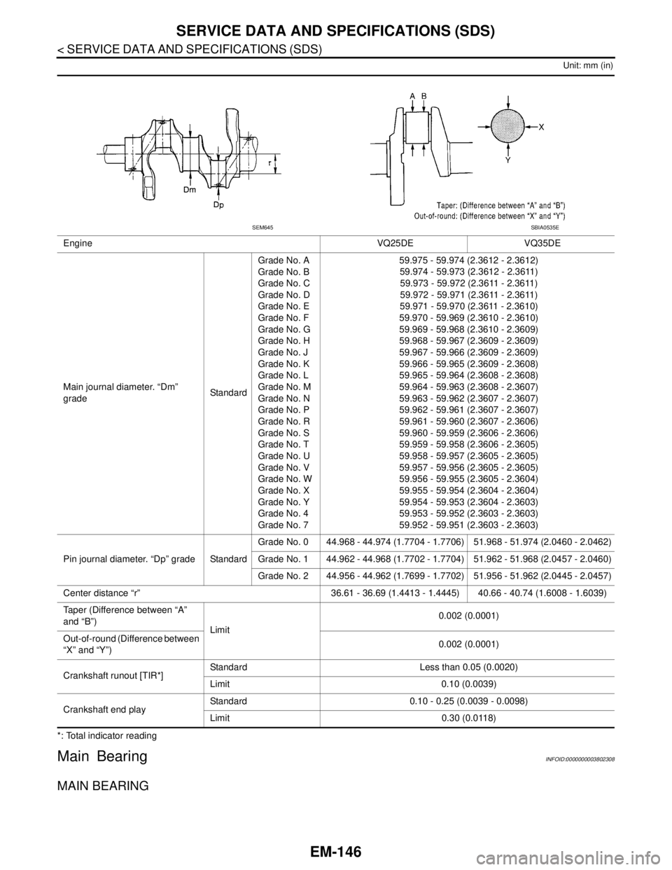
Center distance “r” 36.61 - 36.69 (1.4413 - 1.4445) 40.66 - 40.74 (1.6008 - 1.6039)
Taper (Difference between “A”
and “B”)
Limit0.002 (0.0001)
Out-of-round (Difference between
“X” and “Y”)0.002 (0.0001)
Crankshaft runout [TIR*]Standard Less than 0.05 (0.0020)
Limit 0.10 (0.0039)
Crankshaft end playStandard 0.10 - 0.25 (0.0039 - 0.0098)
Limit 0.30 (0.0118)
SEM645SBIA0535E
Page 2022 of 5121
SERVICE DATA AND SPECIFICATIONS (SDS)
EM-147
< SERVICE DATA AND SPECIFICATIONS (SDS)
C
D
E
F
G
H
I
J
K
L
MA
EM
N
P O
Unit: mm (in)
UNDERSIZE
Unit: mm (in)
MAIN BEARING OIL CLEARANCE
Unit: mm (in)
*: Actual clearance
Connecting Rod BearingINFOID:0000000003802309
CONNECTING ROD BEARING
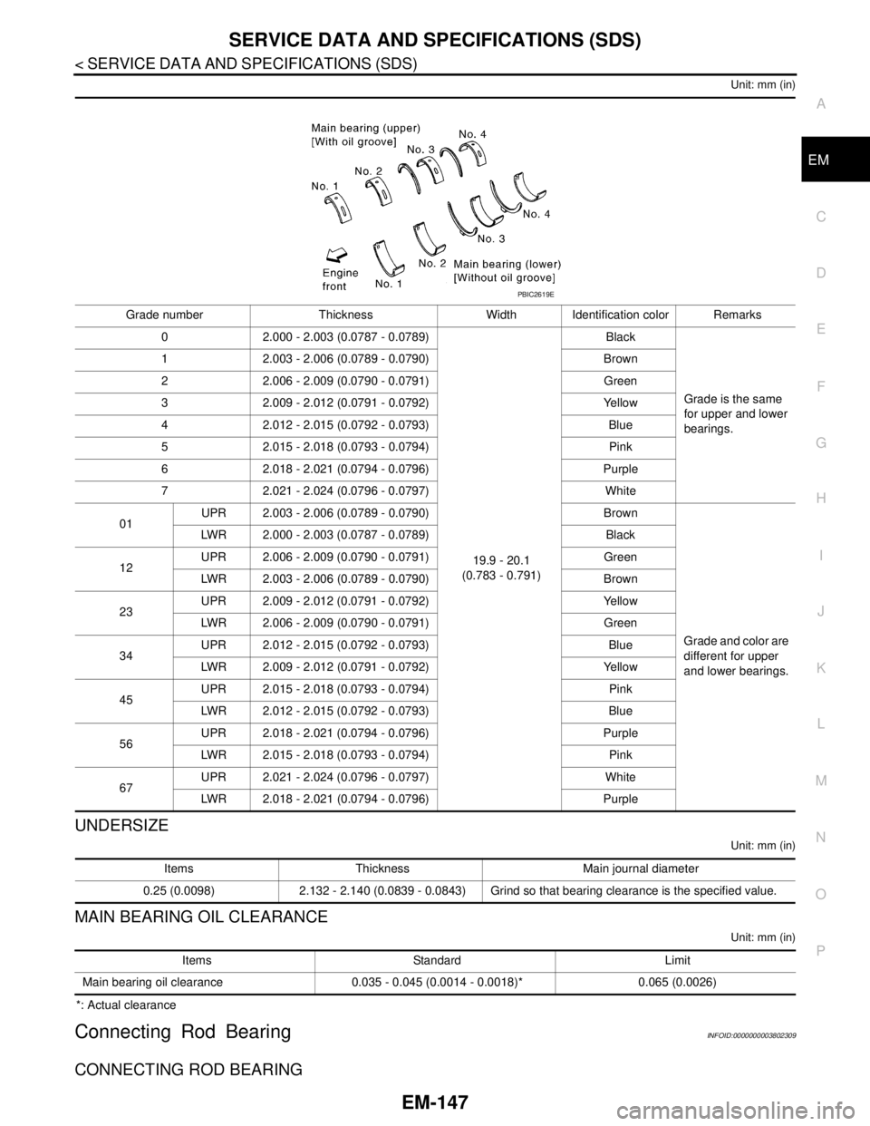
Grade number Thickness Width Identification color Remarks
0 2.000 - 2.003 (0.0787 - 0.0789)
19.9 - 20.1
(0.783 - 0.791)Black
Grade is the same
for upper and lower
bearings. 1 2.003 - 2.006 (0.0789 - 0.0790) Brown
2 2.006 - 2.009 (0.0790 - 0.0791) Green
3 2.009 - 2.012 (0.0791 - 0.0792) Yellow
4 2.012 - 2.015 (0.0792 - 0.0793) Blue
5 2.015 - 2.018 (0.0793 - 0.0794) Pink
6 2.018 - 2.021 (0.0794 - 0.0796) Purple
7 2.021 - 2.024 (0.0796 - 0.0797) White
01UPR 2.003 - 2.006 (0.0789 - 0.0790) Brown
Grade and color are
different for upper
and lower bearings. LWR 2.000 - 2.003 (0.0787 - 0.0789) Black
12UPR 2.006 - 2.009 (0.0790 - 0.0791) Green
LWR 2.003 - 2.006 (0.0789 - 0.0790) Brown
23UPR 2.009 - 2.012 (0.0791 - 0.0792) Yellow
LWR 2.006 - 2.009 (0.0790 - 0.0791) Green
34UPR 2.012 - 2.015 (0.0792 - 0.0793) Blue
LWR 2.009 - 2.012 (0.0791 - 0.0792) Yellow
45UPR 2.015 - 2.018 (0.0793 - 0.0794) Pink
LWR 2.012 - 2.015 (0.0792 - 0.0793) Blue
56UPR 2.018 - 2.021 (0.0794 - 0.0796) Purple
LWR 2.015 - 2.018 (0.0793 - 0.0794) Pink
67UPR 2.021 - 2.024 (0.0796 - 0.0797) White
LWR 2.018 - 2.021 (0.0794 - 0.0796) Purple
PBIC2619E
Items Thickness Main journal diameter
0.25 (0.0098) 2.132 - 2.140 (0.0839 - 0.0843) Grind so that bearing clearance is the specified value.
Items Standard Limit
Main bearing oil clearance 0.035 - 0.045 (0.0014 - 0.0018)* 0.065 (0.0026)
Page 2023 of 5121

EM-148
< SERVICE DATA AND SPECIFICATIONS (SDS)
SERVICE DATA AND SPECIFICATIONS (SDS)
Unit: mm (in)
UNDERSIZE
Unit: mm (in)
CONNECTING ROD BEARING OIL CLEARANCE
Unit: mm (in)
*: Actual clearanceGrade number Thickness Identification color (mark)
0 1.500 - 1.503 (0.0591 - 0.0592) Black
1 1.503 - 1.506 (0.0592 - 0.0593) Brown
2 1.506 - 1.509 (0.0593 - 0.0594) Green
Items Thickness Crank pin journal diameter
0.25 (0.0098) 1.626 - 1.634 (0.0640 - 0.0643) Grind so that bearing clearance is the specified value.
Items Standard Limit
Connecting rod bearing oil clearance 0.020 - 0.045 (0.0008 - 0.0018)* 0.070 (0.0028)
Page 2024 of 5121
EX-1
ENGINE
C
DE
F
G H
I
J
K L
M
SECTION EX
A
EX
N
O P
CONTENTS
EXHAUST SYSTEM
PRECAUTION ................ ...............................2
PRECAUTIONS .............................................. .....2
Removal and Installation ..................................... ......2
PREPARATION ............................................3
PREPARATION .............................................. .....3
Commercial Service Tool .................................... ......3
ON-VEHICLE MAINTENANCE .....................4
EXHAUST SYSTEM ...........................................4
Inspection ............................................................ .....4
ON-VEHICLE REPAIR ..................................5
EXHAUST SYSTEM ...........................................5
Exploded View ..................................................... .....5
Removal and Installation ..........................................5
Inspection .................................................................6
Page 2025 of 5121
EX-2
< PRECAUTION >
PRECAUTIONS
PRECAUTION
PRECAUTIONS
Removal and InstallationINFOID:0000000003793258
CAUTION:
• Be sure to use genuine exhaust system parts or equivalents which are specially designed for heat
resistance, corrosion resistance, and shape.
Perform the operation with the exhaust system fully cooled down because the system will be hot
just after engine stops.
Be careful not to cut your hand on the heat insulator edge.
Page 2026 of 5121
PREPARATION
EX-3
< PREPARATION >
C
D
E
F
G
H
I
J
K
L
MA
EX
N
P O
PREPARATION
PREPARATION
Commercial Service ToolINFOID:0000000003793259
Tool nameDescription
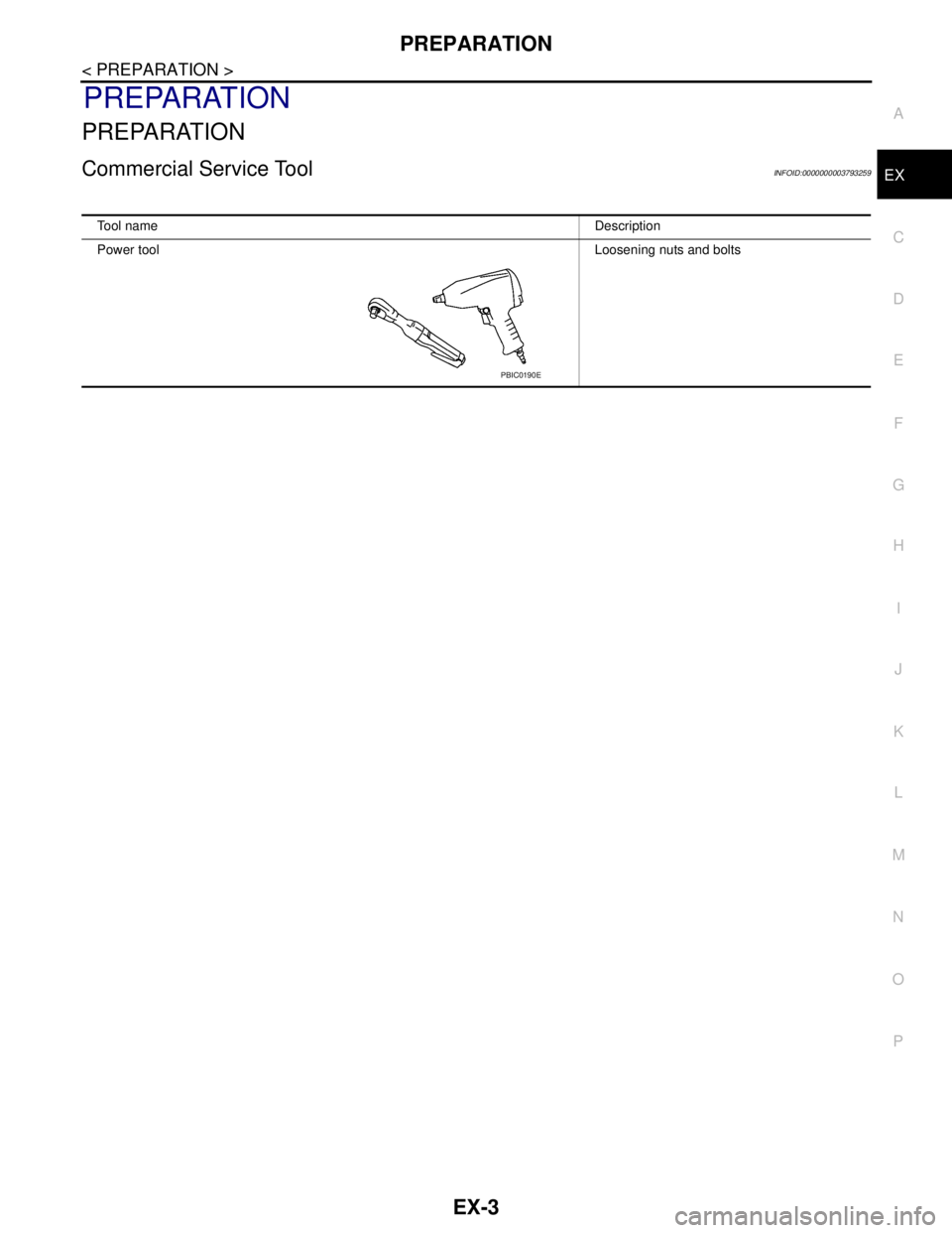
Power toolLoosening nuts and bolts
PBIC0190E
Page 2027 of 5121
EX-4
< ON-VEHICLE MAINTENANCE >
EXHAUST SYSTEM
ON-VEHICLE MAINTENANCE
EXHAUST SYSTEM
InspectionINFOID:0000000003793260
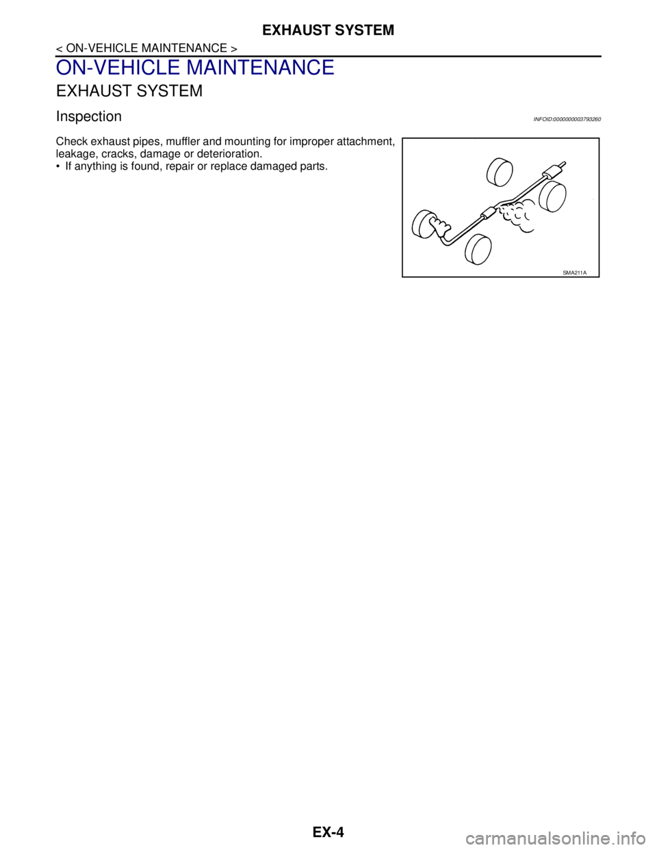
Check exhaust pipes, muffler and mounting for improper attachment,
leakage, cracks, damage or deterioration.
• If anything is found, repair or replace damaged parts.
SMA211A
Page 2028 of 5121
EXHAUST SYSTEM
EX-5
< ON-VEHICLE REPAIR >
C
D
E
F
G
H
I
J
K
L
MA
EX
N
P O
ON-VEHICLE REPAIR
EXHAUST SYSTEM
Exploded ViewINFOID:0000000003793261
Removal and InstallationINFOID:0000000003793262
REMOVAL
Disconnect each joint and mounting using power tool.
INSTALLATION
Note the following, and install in the reverse order of removal.
If exhaust front tube stud bolts were removed, and install them and tighten to the specified torque below.
CAUTION:
Always replace exhaust tube gaskets with new ones when reassembling.
If heat insulator is badly deformed, repair or replace exhaust front tube/center muffler. If deposits
such as mud pile up on the heat insulator, remove them.
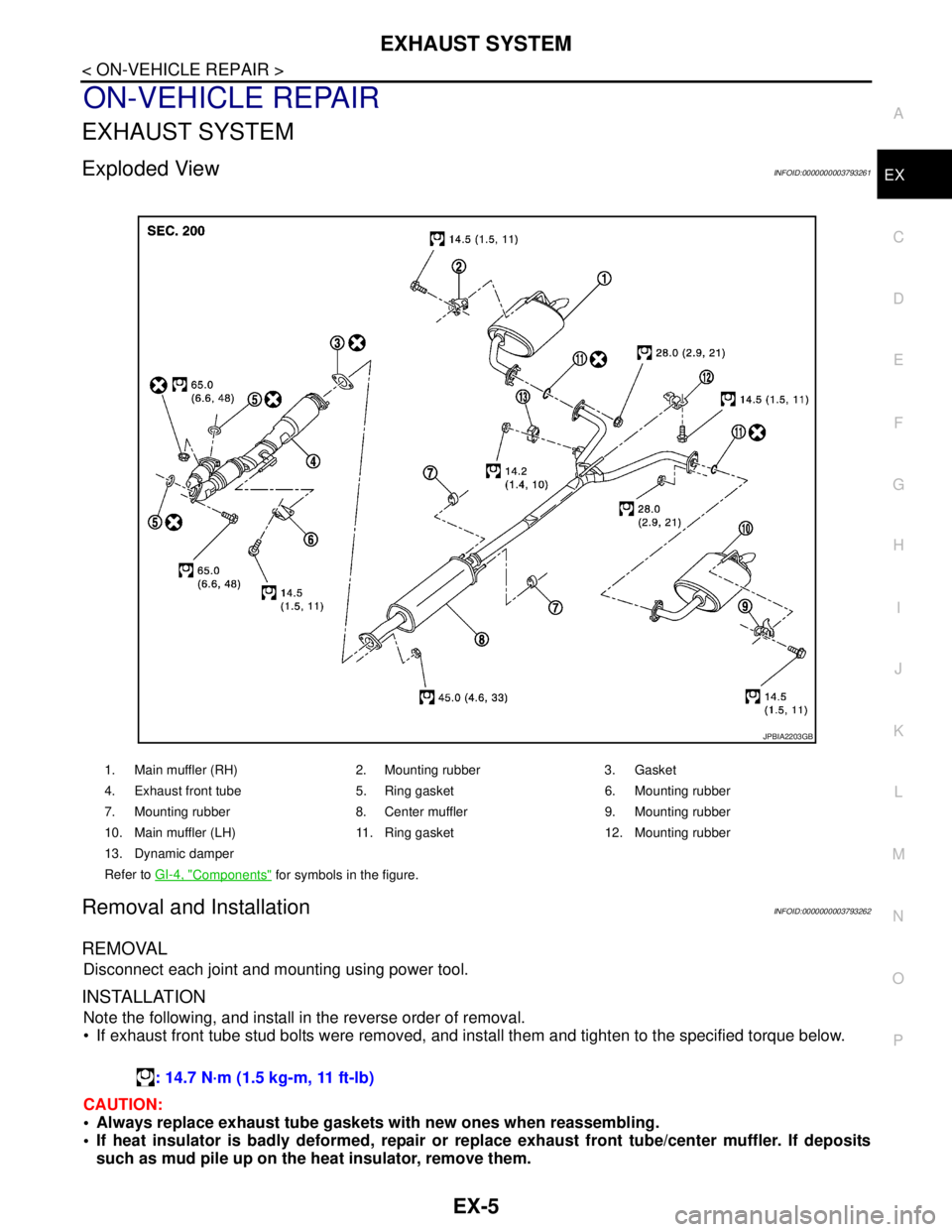
1. Main muffler (RH) 2. Mounting rubber 3. Gasket
4. Exhaust front tube 5. Ring gasket 6. Mounting rubber
7. Mounting rubber 8. Center muffler 9. Mounting rubber
10. Main muffler (LH) 11. Ring gasket 12. Mounting rubber
13. Dynamic damper
Refer to GI-4, "
Components" for symbols in the figure.
JPBIA2203GB
: 14.7 N·m (1.5 kg-m, 11 ft-lb)
Page 2029 of 5121

EX-6
< ON-VEHICLE REPAIR >
EXHAUST SYSTEM
Remove deposits from the sealing surface of each connection. Connect them securely to avoid
gases leakage.
When installing each mounting rubber, use silicon oil to avoid twisting.
Temporarily tighten mounting nuts and bolts. Check each part for unusual interference, and then
tighten them to the specified torque.
When installing each mounting rubber, avoid twisting or unusual extension in up/down, front/rear
and right/left directions.
InspectionINFOID:0000000003793263
INSPECTION AFTER INSTALLATION
Check clearance between tail tube and rear bumper is even.
With engine running, check exhaust tube joints for gas leakage and unusual noises.
Check to ensure that mounting brackets and mounting rubbers are installed properly and free from undue
stress. Improper installation could result in excessive noise and vibration.
Page 2030 of 5121
EXL-1
DRIVER CONTROLS
C
DE
F
G H
I
J
K
M
SECTION EXL
A
B
EXL
N
O P
CONTENTS
EXTERIOR LIGHTING SYSTEM
XENON TYPE
BASIC INSPECTION ....... .............................
7
DIAGNOSIS AND REPAIR WORKFLOW ..... .....7
Work Flow ........................................................... ......7
INSPECTION AND ADJUSTMENT .....................9
ADDITIONAL SERVICE WHEN REPLACING
CONTROL UNIT .................................................... ......
9
ADDITIONAL SERVICE WHEN REPLACING
CONTROL UNIT : Description ..................................
9
ADDITIONAL SERVICE WHEN REPLACING
CONTROL UNIT : Special Repair Requirement .......
9
CONFIGURATION (HEADLAMP LEVELIZER) .... ......9
CONFIGURATION (HEADLAMP LEVELIZER) :
Description ................................................................
9
CONFIGURATION (HEADLAMP LEVELIZER) :
Special Repair Requirement .....................................
9
SENSOR INITIALIZE ............................................. ......9
SENSOR INITIALIZE : Description .........................10
SENSOR INITIALIZE : Special Repair Require-
ment (HEADLAMP AIMING CONTROL SYSTEM)
....
10
FUNCTION DIAGNOSIS ..............................11
HEADLAMP SYSTEM .................................... ....11
System Diagram .................................................. ....11
System Description .................................................11
Component Parts Location ......................................12
Component Description ..........................................12
AUTO LIGHT SYSTEM ......................................13
System Diagram .................................................. ....13
System Description .................................................13
Component Parts Location ......................................14
Component Description ..........................................14
HEADLAMP AIMING CONTROL SYSTEM
(AUTO) ..............................................................
15
System Diagram .................................................. ....15
System Description ..................................................15
Component Parts Location ......................................16
Component Description ...........................................16
FRONT FOG LAMP SYSTEM ...........................17
System Diagram ......................................................17
System Description ..................................................17
Component Parts Location ......................................18
Component Description ..........................................18
TURN SIGNAL AND HAZARD WARNING
LAMP SYSTEM .................................................
19
System Diagram ......................................................19
System Description ..................................................19
Component Parts Location ......................................20
Component Description ..........................................20
PARKING, LICENSE PLATE AND TAIL
LAMPS SYSTEM ..............................................
21
System Diagram .................................................. ....21
System Description ..................................................21
Component Parts Location ......................................22
Component Description ..........................................22
REAR FOG LAMP SYSTEM .............................23
System Diagram ......................................................23
System Description ..................................................23
Component Parts Location ......................................24
Component Description ..........................................24
EXTERIOR LAMP BATTERY SAVER SYS-
TEM ...................................................................
25
System Diagram ......................................................25
System Description ..................................................25
Component Parts Location ......................................26
Component Description ..........................................26
DIAGNOSIS SYSTEM (BCM) ...........................27