steering wheel adjustment NISSAN TEANA 2008 Owner's Manual
[x] Cancel search | Manufacturer: NISSAN, Model Year: 2008, Model line: TEANA, Model: NISSAN TEANA 2008Pages: 5121, PDF Size: 69.03 MB
Page 2491 of 5121
FRONT SUSPENSION MEMBER
FSU-17
< REMOVAL AND INSTALLATION >
C
D
F
G
H
I
J
K
L
MA
B
FSU
N
O
P
NOTE:
Remove the steering knuckle and wheel bearing assembly, steering gear assembly and hydraulic line,
stabilizer bar, transverse link and engine mounting insulator as a unit from the vehicle.
18. Remove the following parts.
Steering knuckle and wheel hub and bearing assembly: refer to FA X - 8 , "
Exploded View".
Steering gear assembly and hydraulic line: refer to ST-18, "
Exploded View" and ST-34, "Exploded
View".
Stabilizer bar: refer to FSU-14, "
Exploded View".
Transverse link: refer to FSU-12, "
Exploded View".
Engine mounting insulator: refer to EM-67, "
Exploded View".
INSTALLATION
Note the following, and install in the reverse order of removal.
Perform final tightening of installation position between front suspension member and transverse links (rub-
ber bushing) under unladen condition with tires on level ground.
InspectionINFOID:0000000003811128
INSPECTION AFTER REMOVAL
Check the front suspension member for significant deformation, cracks, or damages. Replace if necessary.
INSPECTION AFTER INSTALLATION
1. Check wheel sensor harness for proper connection. Refer to BRC-57, "FRONT WHEEL SENSOR :
Exploded View" (without VDC), BRC-151, "FRONT WHEEL SENSOR : Exploded View" (with VDC).
2. Check wheel alignment. Refer to FSU-7, "
Wheel Alignment Inspection".
3. Adjust the neutral position of the steering angle sensor. Refer to BRC-66, "
ADJUSTMENT OF STEERING
ANGLE SENSOR NEUTRAL POSITION : Special Repair Requirement".
Page 2630 of 5121

HAC-2
DTC Logic ...............................................................53
Diagnosis Procedure ..............................................54
Component Inspection ............................................55
B2632, B2633 AIR MIX DOOR MOTOR
(DRIVER SIDE) ..................................................
56
Description ..............................................................56
DTC Logic ...............................................................56
Diagnosis Procedure ..............................................57
B2634, B2635 AIR MIX DOOR MOTOR (PAS-
SENGER SIDE) ..................................................
58
Description ..............................................................58
DTC Logic ...............................................................58
Diagnosis Procedure ..............................................59
B2636, B2637, B2638, B2639, B2654, B2655
MODE DOOR MOTOR ......................................
60
Description ..............................................................60
DTC Logic ...............................................................60
Diagnosis Procedure ..............................................61
B263D B263E, B263F, B2656 INTAKE DOOR
MOTOR ..............................................................
63
Description ..............................................................63
DTC Logic ...............................................................63
Diagnosis Procedure ..............................................64
POWER SUPPLY AND GROUND CIRCUIT .....65
A/C AUTO AMP. .......................................................65
A/C AUTO AMP. : Diagnosis Procedure ................65
A/C CONTROL ..........................................................65
A/C CONTROL : Diagnosis Procedure ...................65
A/C DISPLAY ............................................................66
A/C DISPLAY : Diagnosis Procedure .....................66
A/C AUTO AMP. ................................................67
Description ..............................................................67
Component Function Check ...................................67
Diagnosis Procedure ..............................................67
BLOWER MOTOR .............................................68
Description ..............................................................68
Component Function Check .................................68
Diagnosis Procedure ..............................................68
Component Inspection ............................................71
MAGNET CLUTCH ............................................72
Description ..............................................................72
Component Function Check ...................................72
Diagnosis Procedure ..............................................72
A/C CONTROL SIGNAL CIRCUIT ....................74
Diagnosis Procedure ..............................................74
ECU DIAGNOSIS ........................................75
A/C AUTO AMP. ................................................75
Reference Value .....................................................75
Wiring Diagram - AIR CONDITIONER CONTROL
SYSTEM - ...............................................................
77
Fail-Safe ..................................................................84
DTC Inspection Priority Chart ...............................85
DTC Index ...............................................................85
SYMPTOM DIAGNOSIS ............................87
AIR CONDITIONER CONTROL ........................87
Diagnosis Chart By Symptom .................................87
INSUFFICIENT COOLING .................................88
Description ..............................................................88
Inspection procedure ..............................................88
INSUFFICIENT HEATING .................................91
Description ..............................................................91
Inspection procedure ..............................................91
NOISE ................................................................94
Description ..............................................................94
Inspection procedure ..............................................94
MEMORY FUNCTION DOES NOT OPERATE ...96
Description ..............................................................96
Inspection procedure ..............................................96
PRECAUTION ............................................97
PRECAUTIONS .................................................97
Precaution for Supplemental Restraint System
(SRS) "AIR BAG" and "SEAT BELT PRE-TEN-
SIONER" .................................................................
97
Precaution Necessary for Steering Wheel Rota-
tion after Battery Disconnect ...................................
97
Precaution for Procedure without Cowl Top Cover ...98
Precautions For Xenon Headlamp Service .............98
Working with HFC-134a (R-134a) ...........................98
General Refrigerant Precaution ..............................99
Refrigerant Connection ...........................................99
Service Equipment ................................................101
COMPRESSOR ................................................104
General Precautions .............................................104
FLUORESCENT LEAK DETECTOR ................105
General Precautions .............................................105
WITH 7 INCH DISPLAY
BASIC INSPECTION .................................
106
DIAGNOSIS AND REPAIR WORKFLOW ........106
Work Flow .............................................................106
INSPECTION AND ADJUSTMENT ..................108
WITHOUT INTELLIGENT AIR CONDITIONER
SYSTEM ..................................................................
108
WITHOUT INTELLIGENT AIR CONDITIONER
SYSTEM : Description & Inspection .....................
108
WITHOUT INTELLIGENT AIR CONDITIONER
SYSTEM : Temperature Setting Trimmer .............
110
Page 3190 of 5121

MA-2
HEADLAMP AIMING ADJUSTMENT (HALOGEN
TYPE) : Aiming Adjustment Procedure (High
Beam) .....................................................................
30
EXHAUST SYSTEM ..................................................31
EXHAUST SYSTEM : Inspection ...........................32
CVT FLUID: RE0F10A ..............................................32
CVT FLUID: RE0F10A : Inspection ........................32
CVT FLUID: RE0F10A : Changing .........................33
CVT FLUID: RE0F09B ..............................................34
CVT FLUID: RE0F09B : Inspection ........................34
CVT FLUID: RE0F09B : Changing .........................35
WHEELS (BONDING WEIGHT TYPE) .....................35
WHEELS (BONDING WEIGHT TYPE) : Adjust-
ment ........................................................................
35
BRAKE FLUID LEVEL AND LEAKS ........................37
BRAKE FLUID LEVEL AND LEAKS : Inspection ...37
BRAKE LINES AND CABLES ..................................37
BRAKE LINES AND CABLES : Inspection .............38
BRAKE FLUID ..........................................................38
BRAKE FLUID : Changing ......................................38
DISC BRAKE ............................................................38
DISC BRAKE : Inspection ......................................38
DISC BRAKE : Front Disc Brake ............................39
DISC BRAKE : Rear Disc Brake .............................39
STEERING GEAR AND LINKAGE ...........................39
STEERING GEAR AND LINKAGE : Inspection ......39
POWER STEERING FLUID AND LINES ..................39
POWER STEERING FLUID AND LINES : Inspec-
tion ..........................................................................
40
AXLE AND SUSPENSION PARTS ...........................40
AXLE AND SUSPENSION PARTS : Inspection .....40
DRIVE SHAFT ...........................................................40
DRIVE SHAFT : Inspection .....................................41
BODY MAINTENANCE .....................................42
LOCKS, HINGES AND HOOD LATCH .....................42
LOCKS, HINGES AND HOOD LATCH : Lubricat-
ing ...........................................................................
42
SEAT BELT, BUCKLES, RETRACTORS, AN-
CHORS AND ADJUSTERS ......................................
42
SEAT BELT, BUCKLES, RETRACTORS, AN-
CHORS AND ADJUSTERS : Inspection .................
42
BODY CORROSION .................................................42
BODY CORROSION : Checking Body Corrosion ...42
SERVICE DATA AND SPECIFICATIONS
(SDS) ..........................................................
44
SERVICE DATA AND SPECIFICATIONS
(SDS) .................................................................
44
DRIVE BELTS ...........................................................44
DRIVE BELTS : Drive Belt ......................................44
ENGINE COOLANT ..................................................44
ENGINE COOLANT : Periodical Maintenance
Specification ............................................................
44
ENGINE OIL ..............................................................44
ENGINE OIL :
Periodical Maintenance Specification ....................
44
SPARK PLUG ...........................................................44
SPARK PLUG : Spark Plug ....................................44
ROAD WHEEL ..........................................................44
ROAD WHEEL : Road Wheel .................................44
Page 3730 of 5121
REAR WHEEL HUB AND HOUSING
RAX-5
< ON-VEHICLE REPAIR >
C
E
F
G
H
I
J
K
L
MA
B
RAX
N
O
P
Temporarily tighten nuts to prevent damage to threads and to prevent the ball joint remover from
coming off.
16. Remove hub cap.
INSTALLATION
Note the following, and install in the reverse order of removal.
Perform the final tightening of each of parts under unladen conditions, which were removed when removing
wheel hub and bearing assembly and steering knuckle.
Never reuse cotter pin.
InspectionINFOID:0000000003811101
INSPECTION AFTER REMOVAL
Wheel Hub and Bearing Assembly
Check the wheel hub and bearing assembly for wear, cracks, and damage. Replace if necessary.
Axle Housing
Check the axle housing for wear, cracks, and damage. Replace if necessary.
Ball Joint Inspection
Check for boot breakage, axial looseness, and torque of suspension arm ball joint. Refer to RSU-16, "Inspec-
tion".
INSPECTION AFTER INSTALLATION
1. Check wheel sensor harness for proper connection. Refer to BRC-58, "REAR WHEEL SENSOR :
Exploded View" (without VDC), BRC-152, "REAR WHEEL SENSOR : Exploded View" (with VDC).
2. Adjust parking brake operation (stroke). Refer to PB-2, "
Inspection and Adjustment".
3. Check wheel alignment. Refer to RSU-6, "
Inspection".
4. Adjust neutral position of steering angle sensor (with VDC). Refer to BRC-66, "
ADJUSTMENT OF
STEERING ANGLE SENSOR NEUTRAL POSITION : Special Repair Requirement".
Page 3841 of 5121
REAR LOWER LINK & COIL SPRING
RSU-9
< ON-VEHICLE REPAIR >
C
D
F
G
H
I
J
K
L
MA
B
RSU
N
O
P
Install coil spring by aligning lower end of the coil spring to step (A)
between rubber seat (1) and rear lower link (2).
CAUTION:
Set coil spring so that its paint marks are aligned with the
positions of 3.0 turns (2 places) and 4.0 turns (1 place) or 4.0
turns (2 places) and 5.0 turns (1 place) from the bottom end of
the coil spring.
Perform the final tightening of rear suspension member and axle
installation position (rubber bushing) under unladen condition with
tires on level ground.
InspectionINFOID:0000000003811144
INSPECTION AFTER REMOVAL
Check lower link, bushing and coil spring for deformation, crack, and damage. Replace if necessary.
INSPECTION AFTER INSTALLATION
1. Check wheel alignment. Refer to RSU-6, "Inspection".
2. Adjust neutral position of steering angle sensor (with VDC). Refer to BRC-66, "
ADJUSTMENT OF
STEERING ANGLE SENSOR NEUTRAL POSITION : Special Repair Requirement".
JPEIB0122ZZ
Page 3846 of 5121
RSU-14
< ON-VEHICLE REPAIR >
FRONT LOWER LINK
FRONT LOWER LINK
Exploded ViewINFOID:0000000003811151
Removal and InstallationINFOID:0000000003811152
REMOVAL
1. Remove tire.
2. Remove wheel sensor and sensor harness. Refer to BRC-58, "
REAR WHEEL SENSOR : Exploded View"
(without VDC), BRC-58, "REAR WHEEL SENSOR : Exploded View" (with VDC).
3. Remove rear lower link and coil spring. Refer to RSU-8, "
Exploded View".
4. Remove shock absorber mounting bolt (lower side). Refer to RSU-10, "
Exploded View".
5. Remove front lower link mounting bolts and nuts (axle housing side).
6. Remove front lower link mounting bolts and nuts (rear suspension member side), and then remove front
lower link.
INSTALLATION
Note the following, and install in the reverse order of removal.
Perform final tightening of rear suspension member and axle installation position (rubber bushing), under
unladen conditions with tires on level ground.
InspectionINFOID:0000000003811153
INSPECTION AFTER REMOVAL
Check front lower link and bushing for any deformation, cracks, or damage. Replace if necessary.
INSPECTION AFTER INSTALLATION
1. Check wheel sensor harness for proper connection. Refer to BRC-58, "REAR WHEEL SENSOR :
Exploded View" (without VDC), BRC-152, "REAR WHEEL SENSOR : Exploded View" (with VDC).
2. Check wheel alignment. Refer to RSU-6, "
Inspection".
3. Adjust neutral position of steering angle sensor (with VDC). Refer to BRC-66, "
ADJUSTMENT OF
STEERING ANGLE SENSOR NEUTRAL POSITION : Special Repair Requirement".
1. Upper seat 2. Coil spring 3. Rubber seat
4. Rear lower link 5. Rear suspension member 6. Radius rod
7. Front lower link
Refer to GI-4, "
Components" for symbols in the figure.
JPEIB0108GB
Page 3849 of 5121
REAR SUSPENSION ARM
RSU-17
< REMOVAL AND INSTALLATION >
C
D
F
G
H
I
J
K
L
MA
B
RSU
N
O
P
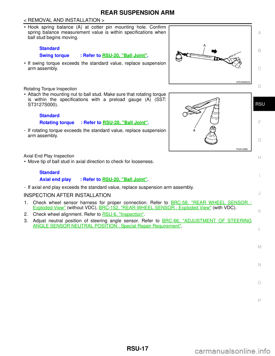
Hook spring balance (A) at cotter pin mounting hole. Confirm
spring balance measurement value is within specifications when
ball stud begins moving.
If swing torque exceeds the standard value, replace suspension
arm assembly.
Rotating Torque Inspection
Attach the mounting nut to ball stud. Make sure that rotating torque
is within the specifications with a preload gauge (A) (SST:
ST3127S000).
- If rotating torque exceeds the standard value, replace suspension
arm assembly.
Axial End Play Inspection
Move tip of ball stud in axial direction to check for looseness.
- If axial end play exceeds the standard value, replace suspension arm assembly.
INSPECTION AFTER INSTALLATION
1. Check wheel sensor harness for proper connection. Refer to BRC-58, "REAR WHEEL SENSOR :
Exploded View" (without VDC), BRC-152, "REAR WHEEL SENSOR : Exploded View" (with VDC).
2. Check wheel alignment. Refer to RSU-6, "
Inspection".
3. Adjust neutral position of steering angle sensor. Refer to BRC-66, "
ADJUSTMENT OF STEERING
ANGLE SENSOR NEUTRAL POSITION : Special Repair Requirement". Standard
Swing torque : Refer to RSU-20, "
Ball Joint".
JPEIA0005ZZ
Standard
Rotating torque : Refer to RSU-20, "
Ball Joint".
PDIA1258E
Standard
Axial end play : Refer to RSU-20, "
Ball Joint".
Page 3851 of 5121
REAR SUSPENSION MEMBER
RSU-19
< REMOVAL AND INSTALLATION >
C
D
F
G
H
I
J
K
L
MA
B
RSU
N
O
P
Perform the final tightening of each of parts under unladen conditions, which were removed when removing
rear suspension assembly.
After final tightening, install auto levelizer control unit (with xenon combination lamp type). Refer to EXL-190,
"Exploded View".
Never reuse cotter pin.
InspectionINFOID:0000000003811162
INSPECTION AFTER REMOVAL
Check rear suspension member for deformation, cracks, or any other damage. Replace if necessary.
INSPECTION AFTER INSTALLATION
1. Check wheel sensor harness for proper connection. Refer to BRC-58, "REAR WHEEL SENSOR :
Exploded View" (without VDC), BRC-152, "REAR WHEEL SENSOR : Exploded View" (with VDC).
2. Adjust parking brake operation (stroke). PB-2, "
Inspection and Adjustment".
3. Check wheel alignment. Refer to RSU-6, "
Inspection".
4. Adjust neutral position of steering angle sensor. Refer to BRC-66, "
ADJUSTMENT OF STEERING
ANGLE SENSOR NEUTRAL POSITION : Special Repair Requirement".
Page 4399 of 5121
STEERING WHEEL
ST-9
< ON-VEHICLE MAINTENANCE >
C
D
E
F
H
I
J
K
L
MA
B
ST
N
O
P
STEERING WHEEL
InspectionINFOID:0000000003806313
STEERING WHEEL AXIAL END PLAY
1. Check installation conditions of steering gear assembly, front suspension assembly, axle and steering col-
umn assembly.
2. Check if movement exists when steering wheel is moved up and down, to the left and right and to the axial
direction.
3. Check the following items when steering wheel axial end play is out of the standard.
Check the steering column assembly mounting condition. Refer to ST-13, "
Exploded View".
Check steering gear assembly mounting condition for looseness. Refer to ST-18, "
Exploded View".
STEERING WHEEL PLAY
1. Turn steering wheel so that front wheels come to the straight-ahead position.
2. Start the engine and lightly turn steering wheel to the left and right until front wheels start to move.
3. Measure steering wheel movement on the outer circumference.
4. Check the following items when steering wheel play is out of the standard.
Check backlash for each joint of steering column assembly.
Check installation condition of steering gear assembly.
NEUTRAL POSITION STEERING WHEEL
1. Check that steering gear assembly, steering column assembly and steering wheel are installed in the cor-
rect position.
2. Perform neutral position inspection after wheel alignment. Refer to FSU-7, "
Wheel Alignment Inspection".
3. Set the vehicle to the straight-ahead position and confirm steering wheel is in the neutral position.
4. Loosen outer socket lock nut and turn inner socket to left and right equally to make fine adjustments if
steering wheel is not in the neutral position.
STEERING WHEEL TURNING FORCE
1. Park the vehicle on a level and dry surface, set parking brake.
2. Tires need to be inflated normal pressure. Refer to WT-5, "
Tire Air Pressure".
3. Start the engine.
4. Bring power steering fluid up to adequate operating temperature.Standard
Steering wheel axial end
play: Refer to ST-37, "
Steering
Wheel Axial End Play and
Play".
Standard
Steering wheel play : Refer to ST-37, "
Steering
Wheel Axial End Play and
Play".
Fluid temperature : 50 – 80°C (122 – 176°F)
Page 4407 of 5121
LOWER SHAFT
ST-17
< ON-VEHICLE REPAIR >
C
D
E
F
H
I
J
K
L
MA
B
ST
N
O
P
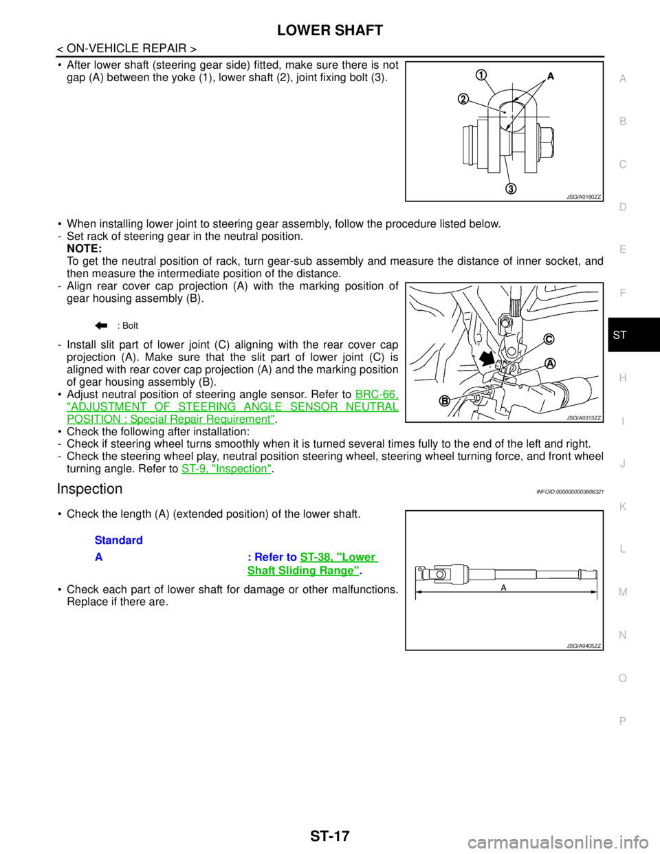
After lower shaft (steering gear side) fitted, make sure there is not
gap (A) between the yoke (1), lower shaft (2), joint fixing bolt (3).
When installing lower joint to steering gear assembly, follow the procedure listed below.
- Set rack of steering gear in the neutral position.
NOTE:
To get the neutral position of rack, turn gear-sub assembly and measure the distance of inner socket, and
then measure the intermediate position of the distance.
- Align rear cover cap projection (A) with the marking position of
gear housing assembly (B).
- Install slit part of lower joint (C) aligning with the rear cover cap
projection (A). Make sure that the slit part of lower joint (C) is
aligned with rear cover cap projection (A) and the marking position
of gear housing assembly (B).
Adjust neutral position of steering angle sensor. Refer to BRC-66,
"ADJUSTMENT OF STEERING ANGLE SENSOR NEUTRAL
POSITION : Special Repair Requirement".
Check the following after installation:
- Check if steering wheel turns smoothly when it is turned several times fully to the end of the left and right.
- Check the steering wheel play, neutral position steering wheel, steering wheel turning force, and front wheel
turning angle. Refer to ST-9, "
Inspection".
InspectionINFOID:0000000003806321
Check the length (A) (extended position) of the lower shaft.
Check each part of lower shaft for damage or other malfunctions.
Replace if there are.
JSGIA0180ZZ
: Bolt
JSGIA0313ZZ
Standard
A : Refer to ST-38, "
Lower
Shaft Sliding Range".
JSGIA0405ZZ