steering wheel adjustment NISSAN TEANA 2008 Owner's Guide
[x] Cancel search | Manufacturer: NISSAN, Model Year: 2008, Model line: TEANA, Model: NISSAN TEANA 2008Pages: 5121, PDF Size: 69.03 MB
Page 4416 of 5121
ST-26
< ON-VEHICLE REPAIR >
STEERING GEAR AND LINKAGE
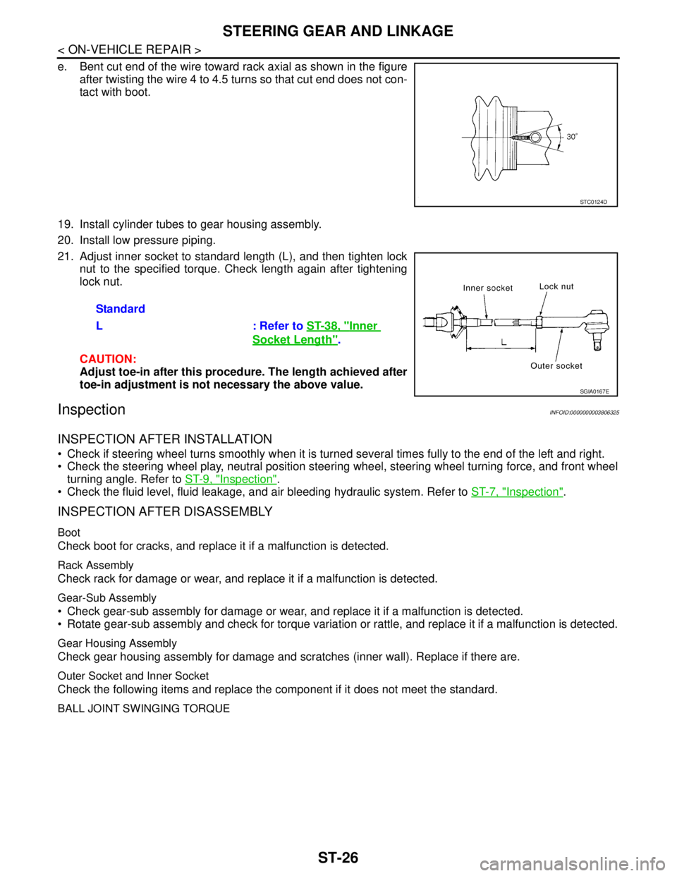
e. Bent cut end of the wire toward rack axial as shown in the figure
after twisting the wire 4 to 4.5 turns so that cut end does not con-
tact with boot.
19. Install cylinder tubes to gear housing assembly.
20. Install low pressure piping.
21. Adjust inner socket to standard length (L), and then tighten lock
nut to the specified torque. Check length again after tightening
lock nut.
CAUTION:
Adjust toe-in after this procedure. The length achieved after
toe-in adjustment is not necessary the above value.
InspectionINFOID:0000000003806325
INSPECTION AFTER INSTALLATION
Check if steering wheel turns smoothly when it is turned several times fully to the end of the left and right.
Check the steering wheel play, neutral position steering wheel, steering wheel turning force, and front wheel
turning angle. Refer to ST-9, "
Inspection".
Check the fluid level, fluid leakage, and air bleeding hydraulic system. Refer to ST-7, "
Inspection".
INSPECTION AFTER DISASSEMBLY
Boot
Check boot for cracks, and replace it if a malfunction is detected.
Rack Assembly
Check rack for damage or wear, and replace it if a malfunction is detected.
Gear-Sub Assembly
Check gear-sub assembly for damage or wear, and replace it if a malfunction is detected.
Rotate gear-sub assembly and check for torque variation or rattle, and replace it if a malfunction is detected.
Gear Housing Assembly
Check gear housing assembly for damage and scratches (inner wall). Replace if there are.
Outer Socket and Inner Socket
Check the following items and replace the component if it does not meet the standard.
BALL JOINT SWINGING TORQUE
STC0124D
Standard
L : Refer to ST-38, "
Inner
Socket Length".
SGIA0167E
Page 4480 of 5121

TM-7
C
E
F
G
H
I
J
K
L
MA
B
TM
N
O
P Precaution for Supplemental Restraint System
(SRS) "AIR BAG" and "SEAT BELT PRE-TEN-
SIONER" ...............................................................
297
Precaution Necessary for Steering Wheel Rota-
tion after Battery Disconnect .................................
297
Precaution for Procedure without Cowl Top Cover ..298
Precaution for On Board Diagnosis (OBD) System
of CVT and Engine ................................................
298
Precaution for TCM and CVT Assembly Replace-
ment ......................................................................
298
Removal and Installation Procedure for CVT Unit
Connector ..............................................................
298
Precaution .............................................................299
Service Notice or Precaution .................................300
ATFTEMP COUNT Conversion Table ..................301
PREPARATION .........................................302
PREPARATION ................................................302
Special Service Tools ............................................302
Commercial Service Tools ....................................302
ON-VEHICLE MAINTENANCE ..................304
CVT FLUID .......................................................304
Inspection ..............................................................304
Changing ...............................................................305
STALL TEST ....................................................306
Inspection and Judgment ......................................306
LINE PRESSURE TEST ...................................308
Inspection and Judgment ......................................308
ROAD TEST .....................................................310
Description ............................................................310
Check before Engine Is Started ............................310
Check at Idle .........................................................311
Cruise Test ............................................................312
CVT POSITION .................................................314
Inspection and Adjustment ....................................314
ON-VEHICLE REPAIR ...............................315
TRANSMISSION CONTROL MODULE ...........315
Exploded View ......................................................315
Removal and Installation .......................................315
CONTROL DEVICE ..........................................317
Exploded View ......................................................317
Removal and Installation .......................................317
Inspection and Adjustment ....................................318
CONTROL CABLE ...........................................319
Exploded View ......................................................319
Removal and Installation .......................................319
Inspection and Adjustment ....................................320
OIL PAN ...........................................................321
Exploded View ......................................................321
Removal and Installation .......................................321
Inspection ..............................................................322
PRIMARY SPEED SENSOR ...........................323
Exploded View .......................................................323
Removal and Installation .......................................323
Inspection ..............................................................323
SECONDARY SPEED SENSOR ....................324
Exploded View .......................................................324
Removal and Installation .......................................324
Inspection ..............................................................324
DIFFERENTIAL SIDE OIL SEAL ....................325
Exploded View .......................................................325
Removal and Installation .......................................325
Inspection ..............................................................326
OIL PUMP FITTING BOLT ..............................327
Description .............................................................327
Exploded View .......................................................327
Removal and Installation .......................................327
Inspection ..............................................................327
AIR BREATHER HOSE ..................................328
Exploded View .......................................................328
Removal and Installation .......................................328
FLUID COOLER SYSTEM ..............................329
Exploded View .......................................................329
Removal and Installation .......................................329
Inspection ..............................................................331
REMOVAL AND INSTALLATION .............332
TRANSAXLE ASSEMBLY ..............................332
Exploded View .......................................................332
Removal and Installation .......................................332
Inspection ..............................................................334
DISASSEMBLY AND ASSEMBLY ............335
TORQUE CONVERTER AND CONVERTER
HOUSING OIL SEAL ......................................
335
Exploded View .......................................................335
Disassembly ..........................................................335
Assembly ...............................................................335
Inspection ..............................................................336
SERVICE DATA AND SPECIFICATIONS
(SDS) ..........................................................
337
SERVICE DATA AND SPECIFICATIONS
(SDS) ...............................................................
337
General Specification ............................................337
Vehicle Speed When Shifting Gears .....................337
Stall Speed ............................................................337
Line Pressure ........................................................337
Solenoid Valves .....................................................338
CVT Fluid Temperature Sensor .............................338
Primary Speed Sensor ..........................................338
Secondary Speed Sensor ......................................338