sunroof NISSAN TEANA 2008 Service Manual
[x] Cancel search | Manufacturer: NISSAN, Model Year: 2008, Model line: TEANA, Model: NISSAN TEANA 2008Pages: 5121, PDF Size: 69.03 MB
Page 1400 of 5121
![NISSAN TEANA 2008 Service Manual DLK-184
< SYMPTOM DIAGNOSIS >[WITH INTELLIGENT KEY SYSTEM]
SQUEAK AND RATTLE TROUBLE DIAGNOSES
Inspection Procedure
INFOID:0000000003941378
Refer to Table of Contents for specific component removal an NISSAN TEANA 2008 Service Manual DLK-184
< SYMPTOM DIAGNOSIS >[WITH INTELLIGENT KEY SYSTEM]
SQUEAK AND RATTLE TROUBLE DIAGNOSES
Inspection Procedure
INFOID:0000000003941378
Refer to Table of Contents for specific component removal an](/img/5/57391/w960_57391-1399.png)
DLK-184
< SYMPTOM DIAGNOSIS >[WITH INTELLIGENT KEY SYSTEM]
SQUEAK AND RATTLE TROUBLE DIAGNOSES
Inspection Procedure
INFOID:0000000003941378
Refer to Table of Contents for specific component removal and installation information.
INSTRUMENT PANEL
Most incidents are caused by contact and movement between:
1. Cluster lid A and instrument panel
2. Acrylic lens and combination meter housing
3. Instrument panel to front pillar garnish
4. Instrument panel to windshield
5. Instrument panel mounting pins
6. Wiring harnesses behind the combination meter
7. A/C defroster duct and duct joint
These incidents can usually be located by tapping or moving the components to duplicate the noise or by
pressing on the components while driving to stop the noise. Most of these incidents can be repaired by apply-
ing felt cloth tape or silicon spray (in hard to reach areas). Urethane pads can be used to insulate wiring har-
ness.
CAUTION:
Never use silicone spray to isolate a squeak or rattle. If the area is saturated with silicone, the recheck
of repair becomes impossible.
CENTER CONSOLE
Components to pay attention to include:
1. Shifter assembly cover to finisher
2. A/C control unit and cluster lid C
3. Wiring harnesses behind audio and A/C control unit
The instrument panel repair and isolation procedures also apply to the center console.
DOORS
Pay attention to the following:
1. Finisher and inner panel making a slapping noise
2. Inside handle escutcheon to door finisher
3. Wiring harnesses tapping
4. Door striker out of alignment causing a popping noise on starts and stops
Tapping or moving the components or pressing on them while driving to duplicate the conditions can isolate
many of these incidents. The areas can usually be insulated with felt cloth tape or insulator foam blocks to
repair the noise.
TRUNK
Trunk noises are often caused by a loose jack or loose items put into the trunk by the customer.
In addition look for the following:
1. Trunk lid dumpers out of adjustment
2. Trunk lid striker out of adjustment
3. Trunk lid torsion bars knocking together
4. A loose license plate or bracket
Most of these incidents can be repaired by adjusting, securing or insulating the item(s) or component(s) caus-
ing the noise.
SUNROOF/HEADLINING
Noises in the sunroof/headlining area can often be traced to one of the following:
1. Sunroof lid, rail, linkage or seals making a rattle or light knocking noise
2. Sunvisor shaft shaking in the holder
3. Front or rear windshield touching headlining and squeaking
Again, pressing on the components to stop the noise while duplicating the conditions can isolate most of these
incidents. Repairs usually consist of insulating with felt cloth tape.
Page 2393 of 5121
EXT-4
< SYMPTOM DIAGNOSIS >
SQUEAK AND RATTLE TROUBLE DIAGNOSES
Check that the cause of a noise is repaired by test driving the vehicle. Operate the vehicle under the same
conditions as when the noise originally occurred. Refer to the notes on the Diagnostic Worksheet.
Inspection ProcedureINFOID:0000000003941540
Refer to Table of Contents for specific component removal and installation information.
INSTRUMENT PANEL
Most incidents are caused by contact and movement between:
1. Cluster lid A and instrument panel
2. Acrylic lens and combination meter housing
3. Instrument panel to front pillar garnish
4. Instrument panel to windshield
5. Instrument panel mounting pins
6. Wiring harnesses behind the combination meter
7. A/C defroster duct and duct joint
These incidents can usually be located by tapping or moving the components to duplicate the noise or by
pressing on the components while driving to stop the noise. Most of these incidents can be repaired by apply-
ing felt cloth tape or silicon spray (in hard to reach areas). Urethane pads can be used to insulate wiring har-
ness.
CAUTION:
Never use silicone spray to isolate a squeak or rattle. If the area is saturated with silicone, the recheck
of repair becomes impossible.
CENTER CONSOLE
Components to pay attention to include:
1. Shifter assembly cover to finisher
2. A/C control unit and cluster lid C
3. Wiring harnesses behind audio and A/C control unit
The instrument panel repair and isolation procedures also apply to the center console.
DOORS
Pay attention to the following:
1. Finisher and inner panel making a slapping noise
2. Inside handle escutcheon to door finisher
3. Wiring harnesses tapping
4. Door striker out of alignment causing a popping noise on starts and stops
Tapping or moving the components or pressing on them while driving to duplicate the conditions can isolate
many of these incidents. Usually insulate the areas with felt cloth tape or insulator foam blocks to repair the
noise.
TRUNK
Trunk noises are often caused by a loose jack or loose items put into the trunk by the customer.
In addition look for the following:
1. Trunk lid dumpers out of adjustment
2. Trunk lid striker out of adjustment
3. Trunk lid torsion bars knocking together
4. A loose license plate or bracket
Most of these incidents can be repaired by adjusting, securing or insulating the item(s) or component(s) caus-
ing the noise.
SUNROOF/HEADLINING
Noises in the sunroof/headlining area can often be traced to one of the following:
1. Sunroof lid, rail, linkage or seals making a rattle or light knocking noise
2. Sunvisor shaft shaking in the holder
3. Front or rear windshield touching headlining and squeaking
Page 2543 of 5121
GI-50
< BASIC INSPECTION >
INSPECTION AND ADJUSTMENT
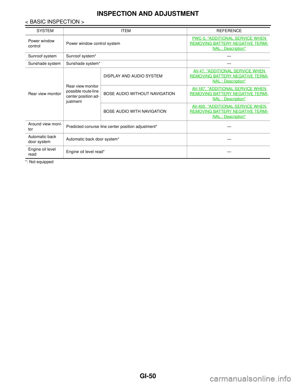
*: Not equippedPower window
controlPower window control systemPWC-5, "
ADDITIONAL SERVICE WHEN
REMOVING BATTERY NEGATIVE TERMI-
NAL : Description"
Sunroof system Sunroof system* —
Sunshade system Sunshade system* —
Rear view monitorRear view monitor
possible route line
center position ad-
justmentDISPLAY AND AUDIO SYSTEMAV- 4 7 , "
ADDITIONAL SERVICE WHEN
REMOVING BATTERY NEGATIVE TERMI-
NAL : Description"
BOSE AUDIO WITHOUT NAVIGATIONAV- 1 8 7 , "
ADDITIONAL SERVICE WHEN
REMOVING BATTERY NEGATIVE TERMI-
NAL : Description"
BOSE AUDIO WITH NAVIGATIONAV- 4 0 0 , "
ADDITIONAL SERVICE WHEN
REMOVING BATTERY NEGATIVE TERMI-
NAL : Description"
Around view moni-
torPredicted conurse line center position adjustment* —
Automatic back
door systemAutomatic back door system* —
Engine oil level
readEngine oil level read* — SYSTEM ITEM REFERENCE
Page 2547 of 5121
GW-4
< SYMPTOM DIAGNOSIS >
SQUEAK AND RATTLE TROUBLE DIAGNOSES
Confirm that the cause of a noise is repaired by test driving the vehicle. Operate the vehicle under the same
conditions as when the noise originally occurred. Refer to the notes on the Diagnostic Worksheet.
Inspection ProcedureINFOID:0000000003943093
Refer to Table of Contents for specific component removal and installation information.
INSTRUMENT PANEL
Most incidents are caused by contact and movement between:
1. Cluster lid A and instrument panel
2. Acrylic lens and combination meter housing
3. Instrument panel to front pillar garnish
4. Instrument panel to windshield
5. Instrument panel mounting pins
6. Wiring harnesses behind the combination meter
7. A/C defroster duct and duct joint
These incidents can usually be located by tapping or moving the components to duplicate the noise or by
pressing on the components while driving to stop the noise. Most of these incidents can be repaired by apply-
ing felt cloth tape or silicon spray (in hard to reach areas). Urethane pads can be used to insulate wiring har-
ness.
CAUTION:
Never use silicone spray to isolate a squeak or rattle. If the area is saturated with silicone, the recheck
of repair becomes impossible.
CENTER CONSOLE
Components to pay attention to include:
1. Shifter assembly cover to finisher
2. A/C control unit and cluster lid C
3. Wiring harnesses behind audio and A/C control unit
The instrument panel repair and isolation procedures also apply to the center console.
DOORS
Pay attention to the following:
1. Finisher and inner panel making a slapping noise
2. Inside handle escutcheon to door finisher
3. Wiring harnesses tapping
4. Door striker out of alignment causing a popping noise on starts and stops
Tapping or moving the components or pressing on them while driving to duplicate the conditions can isolate
many of these incidents. The areas can usually be insulated with felt cloth tape or insulator foam blocks to
repair the noise.
TRUNK
Trunk noises are often caused by a loose jack or loose items put into the trunk by the customer.
In addition look for the following:
1. Trunk lid dumpers out of adjustment
2. Trunk lid striker out of adjustment
3. Trunk lid torsion bars knocking together
4. A loose license plate or bracket
Most of these incidents can be repaired by adjusting, securing or insulating the item(s) or component(s) caus-
ing the noise.
SUNROOF/HEADLINING
Noises in the sunroof/headlining area can often be traced to one of the following:
1. Sunroof lid, rail, linkage or seals making a rattle or light knocking noise
2. Sunvisor shaft shaking in the holder
3. Front or rear windshield touching headlining and squeaking
Page 2554 of 5121
WINDSHIELD GLASS
GW-11
< ON-VEHICLE REPAIR >
C
D
E
F
G
H
I
J
L
MA
B
GW
N
O
P
Removal and InstallationINFOID:0000000003825398
REMOVAL
1. Remove front pillar garnish (LH/RH). Refer to INT-39, "Removal and Installation".
2. Remove partially headlining (front edge). Refer to INT-50, "
NORMAL ROOF : Removal and Installation"
for normal roof or INT-54, "SUNROOF : Removal and Installation" for sunroof.
3. Remove front wiper arms (LH/RH). Refer to WW-105, "
Removal and Installation".
4. Remove front fender cover (LH/RH). Refer to DLK-199, "
Exploded View".
5. Remove cowl top cover. Refer to EXT-20, "
Removal and Installation".
6. Remove roof side molding (LH/RH). Refer to EXT-29, "
Removal and Installation".
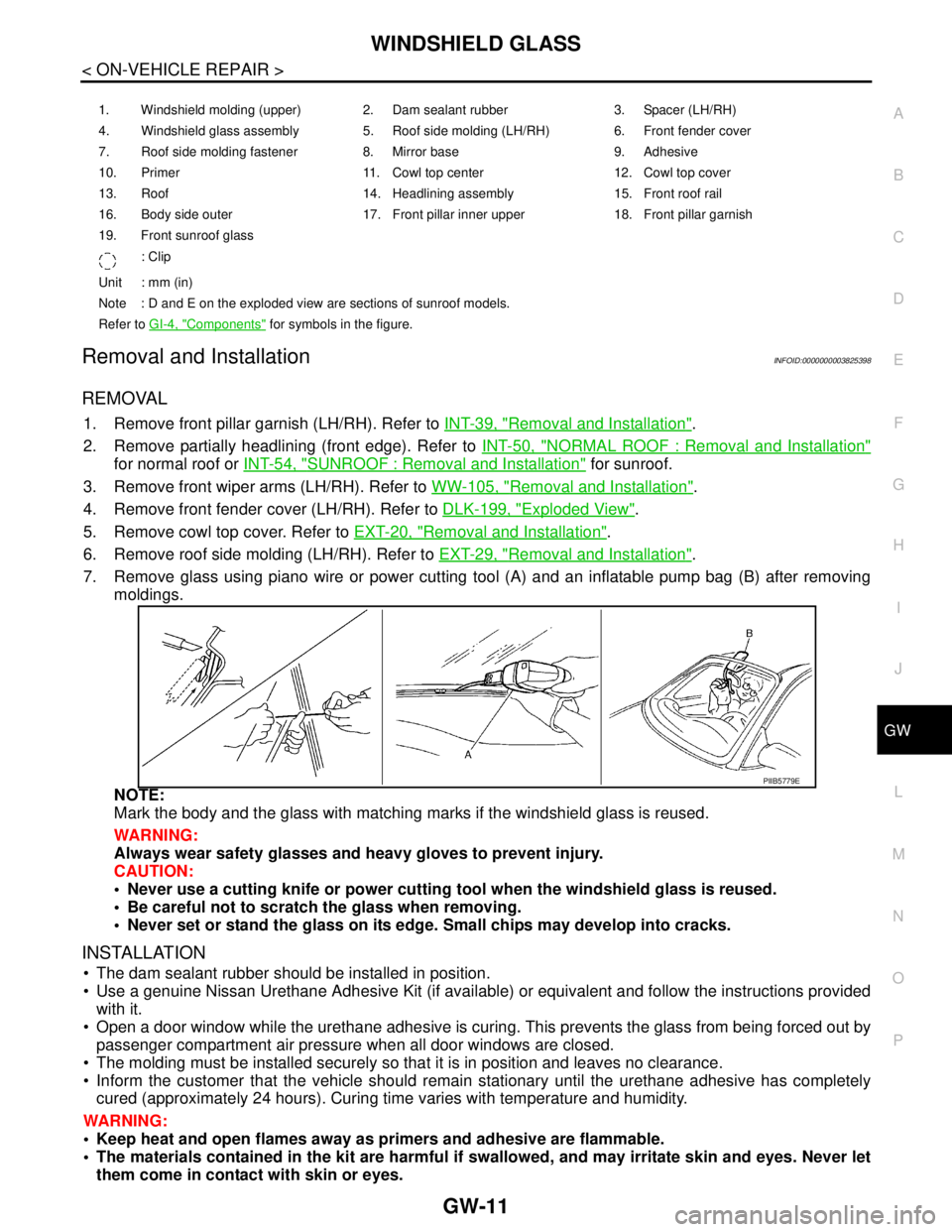
7. Remove glass using piano wire or power cutting tool (A) and an inflatable pump bag (B) after removing
moldings.
NOTE:
Mark the body and the glass with matching marks if the windshield glass is reused.
WARNING:
Always wear safety glasses and heavy gloves to prevent injury.
CAUTION:
Never use a cutting knife or power cutting tool when the windshield glass is reused.
Be careful not to scratch the glass when removing.
Never set or stand the glass on its edge. Small chips may develop into cracks.
INSTALLATION
The dam sealant rubber should be installed in position.
Use a genuine Nissan Urethane Adhesive Kit (if available) or equivalent and follow the instructions provided
with it.
Open a door window while the urethane adhesive is curing. This prevents the glass from being forced out by
passenger compartment air pressure when all door windows are closed.
The molding must be installed securely so that it is in position and leaves no clearance.
Inform the customer that the vehicle should remain stationary until the urethane adhesive has completely
cured (approximately 24 hours). Curing time varies with temperature and humidity.
WARNING:
Keep heat and open flames away as primers and adhesive are flammable.
The materials contained in the kit are harmful if swallowed, and may irritate skin and eyes. Never let
them come in contact with skin or eyes.
1. Windshield molding (upper) 2. Dam sealant rubber 3. Spacer (LH/RH)
4. Windshield glass assembly 5. Roof side molding (LH/RH) 6. Front fender cover
7. Roof side molding fastener 8. Mirror base 9. Adhesive
10. Primer 11. Cowl top center 12. Cowl top cover
13. Roof 14. Headlining assembly 15. Front roof rail
16. Body side outer 17. Front pillar inner upper 18. Front pillar garnish
19. Front sunroof glass
: Clip
Unit : mm (in)
Note : D and E on the exploded view are sections of sunroof models.
Refer to GI-4, "
Components" for symbols in the figure.
PIIB5779E
Page 2559 of 5121
GW-16
< ON-VEHICLE REPAIR >
REAR WINDOW GLASS
3. Remove rear parcel shelf finisher. Refer to INT-43, "Removal and Installation".
4. Remove partially the headlining assembly (rear edge). Refer to INT-50, "
NORMAL ROOF : Removal and
Installation"for normal roof and to INT-54, "SUNROOF : Removal and Installation" for sunroof.
5. Remove connectors and ground from the rear window defogger.
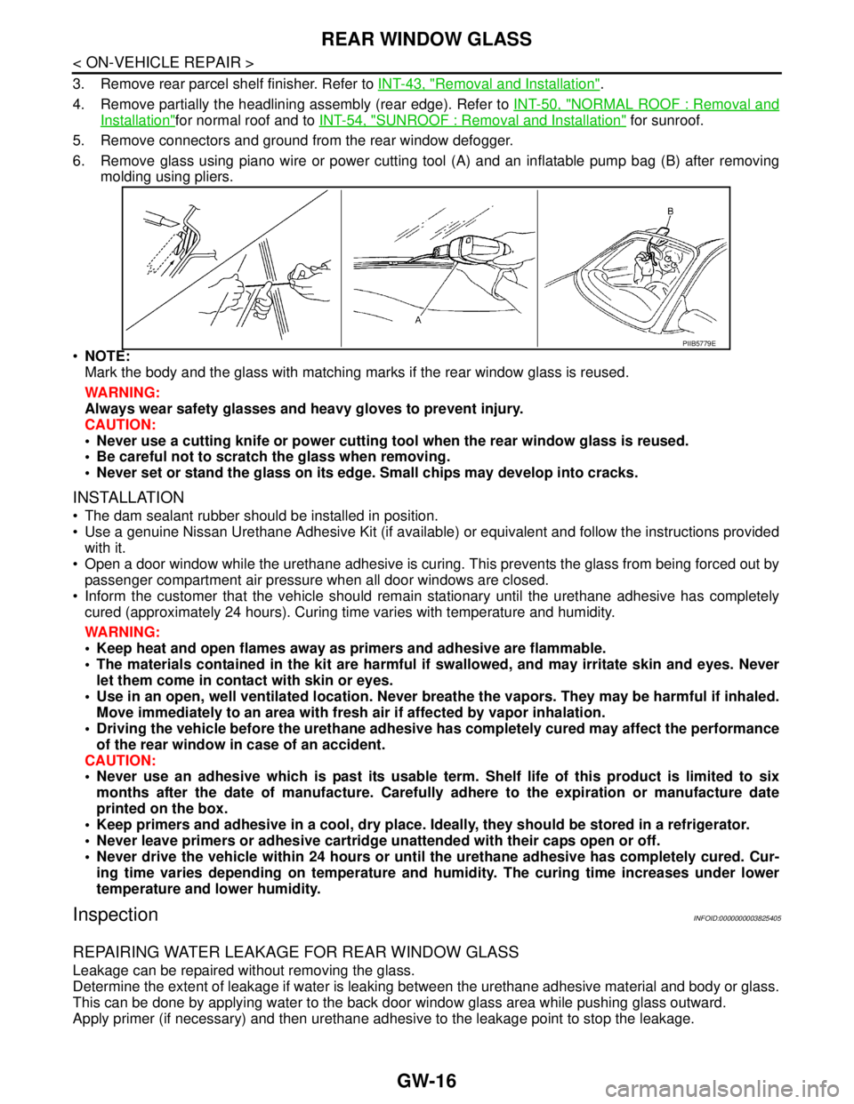
6. Remove glass using piano wire or power cutting tool (A) and an inflatable pump bag (B) after removing
molding using pliers.
NOTE:
Mark the body and the glass with matching marks if the rear window glass is reused.
WARNING:
Always wear safety glasses and heavy gloves to prevent injury.
CAUTION:
Never use a cutting knife or power cutting tool when the rear window glass is reused.
Be careful not to scratch the glass when removing.
Never set or stand the glass on its edge. Small chips may develop into cracks.
INSTALLATION
The dam sealant rubber should be installed in position.
Use a genuine Nissan Urethane Adhesive Kit (if available) or equivalent and follow the instructions provided
with it.
Open a door window while the urethane adhesive is curing. This prevents the glass from being forced out by
passenger compartment air pressure when all door windows are closed.
Inform the customer that the vehicle should remain stationary until the urethane adhesive has completely
cured (approximately 24 hours). Curing time varies with temperature and humidity.
WARNING:
Keep heat and open flames away as primers and adhesive are flammable.
The materials contained in the kit are harmful if swallowed, and may irritate skin and eyes. Never
let them come in contact with skin or eyes.
Use in an open, well ventilated location. Never breathe the vapors. They may be harmful if inhaled.
Move immediately to an area with fresh air if affected by vapor inhalation.
Driving the vehicle before the urethane adhesive has completely cured may affect the performance
of the rear window in case of an accident.
CAUTION:
Never use an adhesive which is past its usable term. Shelf life of this product is limited to six
months after the date of manufacture. Carefully adhere to the expiration or manufacture date
printed on the box.
Keep primers and adhesive in a cool, dry place. Ideally, they should be stored in a refrigerator.
Never leave primers or adhesive cartridge unattended with their caps open or off.
Never drive the vehicle within 24 hours or until the urethane adhesive has completely cured. Cur-
ing time varies depending on temperature and humidity. The curing time increases under lower
temperature and lower humidity.
InspectionINFOID:0000000003825405
REPAIRING WATER LEAKAGE FOR REAR WINDOW GLASS
Leakage can be repaired without removing the glass.
Determine the extent of leakage if water is leaking between the urethane adhesive material and body or glass.
This can be done by applying water to the back door window glass area while pushing glass outward.
Apply primer (if necessary) and then urethane adhesive to the leakage point to stop the leakage.
PIIB5779E
Page 2979 of 5121

INT-2
Precaution for Supplemental Restraint System
(SRS) "AIR BAG" and "SEAT BELT PRE-TEN-
SIONER" .................................................................
27
Precaution Necessary for Steering Wheel Rota-
tion after Battery Disconnect ..................................
27
Precaution for Procedure without Cowl Top Cover ...28
Precaution for Work ................................................28
PREPARATION ...........................................29
PREPARATION .................................................29
Commercial Service Tools ......................................29
ON-VEHICLE REPAIR ................................30
FRONT DOOR FINISHER .................................30
DRIVER SIDE ............................................................30
DRIVER SIDE : Exploded View ..............................30
DRIVER SIDE : Removal and Installation ..............30
PASSENGER SIDE ...................................................32
PASSENGER SIDE : Exploded View .....................33
PASSENGER SIDE : Removal and Installation .....33
REAR DOOR FINISHER ....................................36
Exploded View ........................................................36
Removal and Installation ........................................36
BODY SIDE TRIM ..............................................39
Exploded View ........................................................39
Removal and Installation ........................................39
REAR PARCEL SHELF FINISHER ...................43
Exploded View ........................................................43
Removal and Installation ........................................43
REAR SUNSHADE ............................................45
Exploded View ........................................................45
Removal and Installation .........................................45
FLOOR TRIM .....................................................47
Exploded View ........................................................47
Removal and Installation .........................................47
HEADLINING .....................................................49
NORMAL ROOF ........................................................49
NORMAL ROOF : Exploded View ..........................49
NORMAL ROOF : Removal and Installation ...........50
SUNROOF .................................................................52
SUNROOF : Exploded View ...................................53
SUNROOF : Removal and Installation ....................54
TRUNK ROOM TRIM .........................................57
Exploded View ........................................................57
Removal and Installation .........................................57
TRUNK LID TRIM ..............................................59
Exploded View ........................................................59
Removal and Installation .........................................59
REAR SUNSHADE CONTROL UNIT ................61
Exploded View ........................................................61
Removal and Installation .........................................61
REAR SUNSHADE SWITCH .............................62
FRONT .......................................................................62
FRONT : Exploded View .........................................62
FRONT : Removal and Installation .........................62
REAR .........................................................................62
REAR : Exploded View ...........................................63
REAR : Removal and Installation ............................63
Page 3000 of 5121
SQUEAK AND RATTLE TROUBLE DIAGNOSES
INT-23
< SYMPTOM DIAGNOSIS >
C
D
E
F
G
H
I
K
L
MA
B
INT
N
O
P
Inspection ProcedureINFOID:0000000003887244
Refer to Table of Contents for specific component removal and installation information.
INSTRUMENT PANEL
Most incidents are caused by contact and movement between:
1. Cluster lid A and instrument panel
2. Acrylic lens and combination meter housing
3. Instrument panel to front pillar garnish
4. Instrument panel to windshield
5. Instrument panel mounting pins
6. Wiring harnesses behind the combination meter
7. A/C defroster duct and duct joint
These incidents can usually be located by tapping or moving the components to duplicate the noise or by
pressing on the components while driving to stop the noise. Most of these incidents can be repaired by apply-
ing felt cloth tape or silicon spray (in hard to reach areas). Urethane pads can be used to insulate wiring har-
ness.
CAUTION:
Never use silicone spray to isolate a squeak or rattle. If the area is saturated with silicone, the recheck
of repair becomes impossible.
CENTER CONSOLE
Components to pay attention to include:
1. Shifter assembly cover to finisher
2. A/C control unit and cluster lid C
3. Wiring harnesses behind audio and A/C control unit
The instrument panel repair and isolation procedures also apply to the center console.
DOORS
Pay attention to the following:
1. Finisher and inner panel making a slapping noise
2. Inside handle escutcheon to door finisher
3. Wiring harnesses tapping
4. Door striker out of alignment causing a popping noise on starts and stops
Tapping or moving the components or pressing on them while driving to duplicate the conditions can isolate
many of these incidents. The areas can usually be insulated with felt cloth tape or insulator foam blocks to
repair the noise.
TRUNK
Trunk noises are often caused by a loose jack or loose items put into the trunk by the customer.
In addition look for the following:
1. Trunk lid dumpers out of adjustment
2. Trunk lid striker out of adjustment
3. Trunk lid torsion bars knocking together
4. A loose license plate or bracket
Most of these incidents can be repaired by adjusting, securing or insulating the item(s) or component(s) caus-
ing the noise.
SUNROOF/HEADLINING
Noises in the sunroof/headlining area can often be traced to one of the following:
1. Sunroof lid, rail, linkage or seals making a rattle or light knocking noise
2. Sunvisor shaft shaking in the holder
3. Front or rear windshield touching headlining and squeaking
Again, pressing on the components to stop the noise while duplicating the conditions can isolate most of these
incidents. Repairs usually consist of insulating with felt cloth tape.
Page 3029 of 5121
INT-52
< ON-VEHICLE REPAIR >
HEADLINING
CAUTION:
When removing, 2 workers are required. (1 for the front and rear of headlining)
Cover center console finisher upper surface with a shop cloth to prevent it from being damaged.
Never bend headlining when removing.
13. Remove the following parts after removing headlining.
Map lamp assembly. Refer to INL-89, "
Removal and Installation".
Personal lamp assembly. Refer to INL-96, "
Removal and Installation".
Roof harness assembly.
Antenna feeder assembly. Refer to AV-44, "
Harness Layout".
INSTALLATION
Install in the reverse order of removal.
CAUTION:
Install headlining assembly after inserting clips to clip holder of headlining rear end.
Never bend headlining when installing.
SUNROOF
Page 3030 of 5121
HEADLINING
INT-53
< ON-VEHICLE REPAIR >
C
D
E
F
G
H
I
K
L
MA
B
INT
N
O
P
SUNROOF : Exploded ViewINFOID:0000000003826877
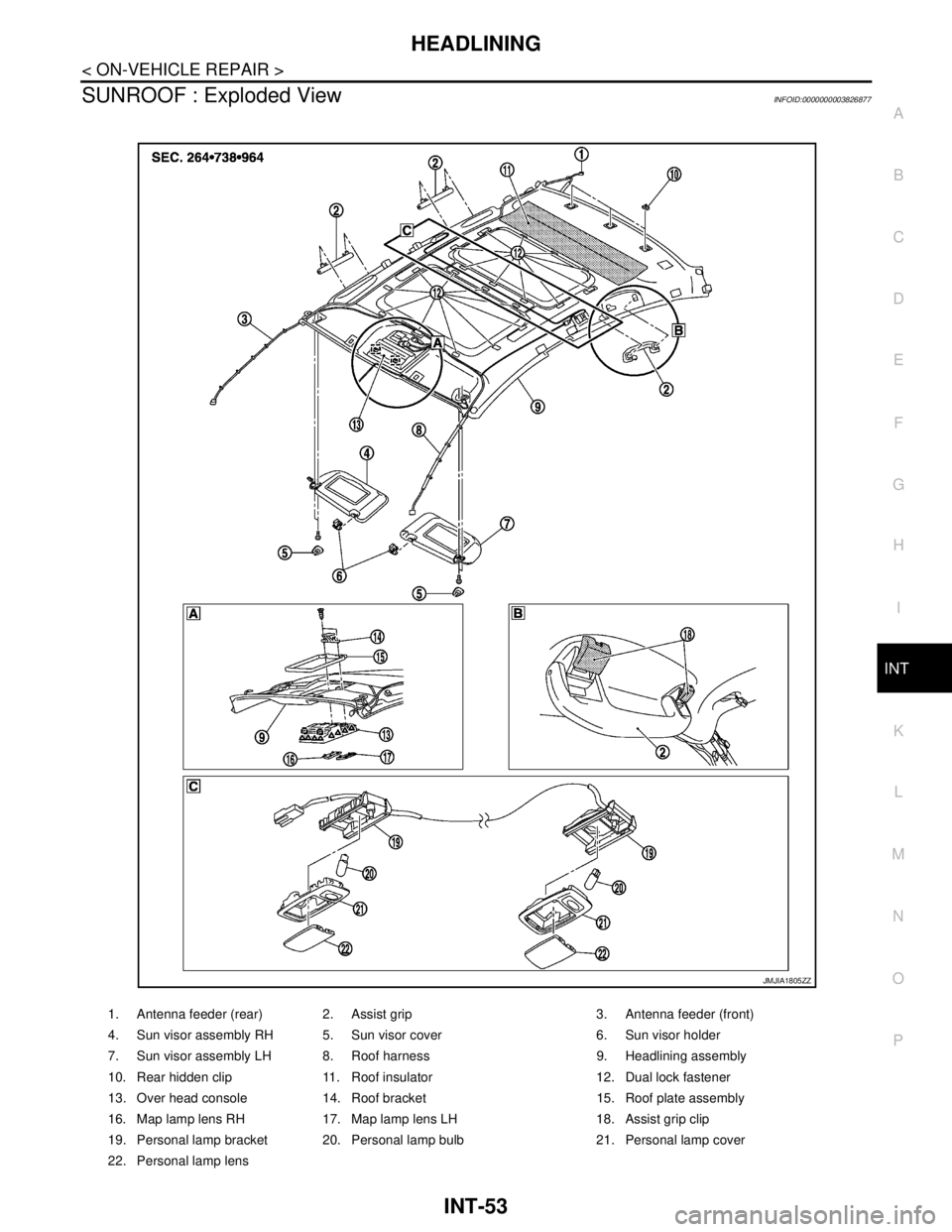
1. Antenna feeder (rear) 2. Assist grip 3. Antenna feeder (front)
4. Sun visor assembly RH 5. Sun visor cover 6. Sun visor holder
7. Sun visor assembly LH 8. Roof harness 9. Headlining assembly
10. Rear hidden clip 11. Roof insulator 12. Dual lock fastener
13. Over head console 14. Roof bracket 15. Roof plate assembly
16. Map lamp lens RH 17. Map lamp lens LH 18. Assist grip clip
19. Personal lamp bracket 20. Personal lamp bulb 21. Personal lamp cover
22. Personal lamp lens
JMJIA1805ZZ