stall speed NISSAN TEANA 2014 Service Manual
[x] Cancel search | Manufacturer: NISSAN, Model Year: 2014, Model line: TEANA, Model: NISSAN TEANA 2014Pages: 4801, PDF Size: 51.2 MB
Page 3273 of 4801
MWI-18
< SYSTEM DESCRIPTION >
DIAGNOSIS SYSTEM (METER)
DIAGNOSIS SYSTEM (METER)
DescriptionINFOID:0000000009461692
COMBINATION METER SELF-DIAGNOSIS MODE
The following meter functions can be checked during Combination Meter Self-Diagnosis Mode:
• Pointer sweep of speedometer, tachometer and gauges.
• Illumination of all LCD segments and color patterns for meter displays.
• Illumination of all lamps/LEDs that are controlled by the combination meter (regardless of switch status).
STARTING COMBINATION METER SELF-DIAGNOSIS MODE
NOTE:
• Check combination meter power supply and ground circuits if self-diagnosis mode does not start. Refer to
MWI-58, "COMBINATION METER : Diagnosis Procedure"
. Replace combination meter if power supply and
ground circuits are found to be normal and self-diagnosis mode does not start. Refer to MWI-82, "Removal
and Installation".
• Combination meter self-diagnosis mode will function with t he ignition switch in ON. Combination meter self-
diagnosis mode will exit upon turning the ignition switch to OFF.
How to Initiate Self-Diagnosis Mode
1. Press and hold the trip reset switch while turning the ignition switch ON. After 2 seconds release trip reset switch, then press the trip reset switch 3 times within 7 seconds after the ignition switch is turned ON.
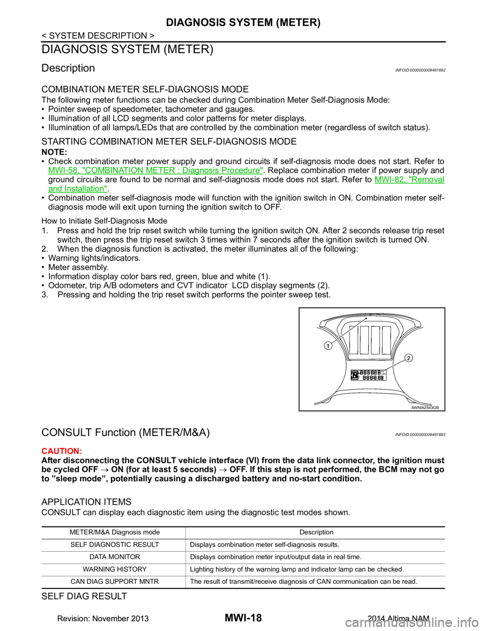
2. When the diagnosis function is activated, the meter illuminates all of the following:
• Warning lights/indicators.
• Meter assembly.
• Information display color bars red, green, blue and white (1).
• Odometer, trip A/B odometers and CVT indicator LCD display segments (2).
3. Pressing and holding the trip reset switch performs the pointer sweep test.
CONSULT Function (METER/M&A)INFOID:0000000009461693
CAUTION:
After disconnecting the CONSULT vehicle interface (VI) from the data link connector, the ignition must
be cycled OFF → ON (for at least 5 seconds) → OFF. If this step is not performed, the BCM may not go
to ”sleep mode”, potentially causing a di scharged battery and no-start condition.
APPLICATION ITEMS
CONSULT can display each diagnostic item using the diagnostic test modes shown.
SELF DIAG RESULT
AWNIA2543GB
METER/M&A Diagnosis mode Description
SELF DIAGNOSTIC RESULT Displays combin ation meter self-diagnosis results.
DATA MONITOR Displays combination meter input/output data in real time.
WARNING HISTORY Lighting history of the warning lamp and indicator lamp can be checked.
CAN DIAG SUPPORT MNTR The result of transmit/receive diagnosis of CAN communication can be read.
Revision: November 20132014 Altima NAMRevision: November 20132014 Altima NAM
Page 3310 of 4801
MWI
B2205 VEHICLE SPEEDMWI-55
< DTC/CIRCUIT DIAGNOSIS >
C
D E
F
G H
I
J
K L
M B
A
O P
B2205 VEHICLE SPEED
DescriptionINFOID:0000000009461706
The ABS actuator and electric unit (control unit) provi des a vehicle speed signal to the combination meter via
CAN communication lines.
DTC LogicINFOID:0000000009461707
Diagnosis ProcedureINFOID:0000000009461708
1.CHECK COMBINATION METER INPUT SIGNAL
1. Start engine and select METER/M&A on CONSULT.
2. Using SPEED METER on DATA MONITOR, compar e the value of DATA MONITOR with speedometer
pointer of combination meter. Speedometer and DATA MONITOR indications should be close.
Is the inspection result normal?
YES >> Perform ABS actuator and electric uni t (control unit) self-diagnosis. Refer to BRC-33, "CONSULT
Function (ABS)".
NO >> Replace combination meter. Refer to MWI-82, "Removal and Installation"
.
DTC CONSULT Detection condition Possible malfunction location
B2205 VEHICLE SPEED CIRC
[B2205] Malfunction is detected when an erroneous
speed signal is received for 2 seconds or
more. • Combination meter
• ABS actuator and electric unit (control unit)
Revision: November 20132014 Altima NAMRevision: November 20132014 Altima NAM
Page 3386 of 4801
![NISSAN TEANA 2014 Service Manual
PCS
SYSTEMPCS-37
< SYSTEM DESCRIPTION > [POWER DISTRIBUTION SYSTEM]
C
D E
F
G H
I
J
K L
B
A
O P
N
POWER SUPPLY POSITION CHANGE TABLE BY
PUSH-BUTTON IGNITION SWITCH OPERA-
TION
The power supply pos](/img/5/57390/w960_57390-3385.png "NISSAN TEANA 2014 Service Manual
PCS
SYSTEMPCS-37
< SYSTEM DESCRIPTION > [POWER DISTRIBUTION SYSTEM]
C
D E
F
G H
I
J
K L
B
A
O P
N
POWER SUPPLY POSITION CHANGE TABLE BY
PUSH-BUTTON IGNITION SWITCH OPERA-
TION
The power supply pos")
PCS
SYSTEMPCS-37
< SYSTEM DESCRIPTION > [POWER DISTRIBUTION SYSTEM]
C
D E
F
G H
I
J
K L
B
A
O P
N
POWER SUPPLY POSITION CHANGE TABLE BY
PUSH-BUTTON IGNITION SWITCH OPERA-
TION
The power supply position changing operation can be performed with the following operations.
NOTE:
• When an Intelligent Key is within the detection area of inside key antenna and when Intelligent Key backside
is contacted to push-button ignition switch, it is equivalent to the operations below.
• When starting the engine, the BCM monitors under the engine start conditions:
- Brake pedal operating condition
- Selector lever position
- Vehicle speed
Vehicle speed: less than 4 km/h (2.5 MPH)
Vehicle speed: 4 km/h (2.5 MPH) or more
Emergency stop operation
• Press and hold the push-button ignition switch for 2 seconds or more.
• Press the push-button ignition switch 3 times or more within 1.5 seconds. Power supply position
Engine start/stop condition
Push-button ignition switch
operation frequency
Selector lever position Brake pedal operation condition
OFF → ACC — Not depressed 1
OFF → ACC → ON — Not depressed 2
OFF → ACC → ON → OFF — Not depressed 3
OFF → START
ACC → START
ON → START P or N position Depressed 1
Engine is running → OFF — — 1
Power supply position Engine start/stop condition
Push-button ignition switch
operation frequency
Selector lever position Brake pedal operation condition
Engine is running → ACC — — Emergency stop operation
Engine stall return operation
while driving N position Not depressed 1
Revision: November 20132014 Altima NAMRevision: November 20132014 Altima NAM
Page 3689 of 4801
RF-24
< DTC/CIRCUIT DIAGNOSIS >
POWER SUPPLY AND GROUND CIRCUIT
Is the inspection result normal?
YES >> Refer to RF-24, "MOONROOF MOTOR ASSEMBLY : Component Inspection".
NO >> Repair or replace the harness or connectors.
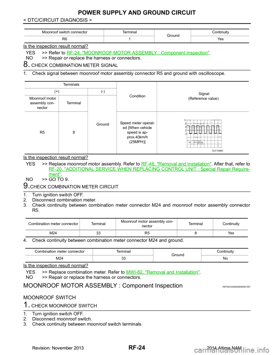
8. CHECK COMBINATION METER SIGNAL
1. Check signal between moonroof motor assembly connector R5 and ground with oscilloscope.
Is the inspection result normal?
YES >> Replace moonroof motor assembly. Refer to RF-46, "Removal and Installation". After that, refer to
RF-20, "ADDITIONAL SERVICE WHEN REPLACING CONTROL UNIT : Special Repair Require-
ment".
NO >> GO TO 9.
9.CHECK COMBINATION METER CIRCUIT
1. Turn ignition switch OFF.
2. Disconnect combination meter.
3. Check continuity between combination meter c onnector M24 and moonroof motor assembly connector
R5.
4. Check continuity between combination meter connector M24 and ground.
Is the inspection result normal?
YES >> Replace combination meter. Refer to MWI-82, "Removal and Installation".
NO >> Repair or replace the harness or connectors.
MOONROOF MOTOR ASSEMBLY : Component InspectionINFOID:0000000009461307
MOONROOF SWITCH
1. CHECK MOONROOF SWITCH
1. Turn ignition switch OFF.
2. Disconnect moonroof switch.
3. Check continuity between moonroof switch terminals.
Moonroof switch connector Terminal GroundContinuity
R6 1 Yes
Te r m i n a l s
Condition Signal
(Reference value)
(+) (-)
Moonroof motor assembly con-
nector Te r m i n a l
Ground
R5 8 Speed meter operat-
ed [When vehicle
speed is ap-
prox.40km/h (25MPH)]
ELF1080D
Combination meter connector Terminal Moonroof motor
assembly con-
nector Terminal Continuity
M24 33 R5 8 Yes
Combination meter connector Terminal GroundContinuity
M24 33 No
Revision: November 20132014 Altima NAMRevision: November 20132014 Altima NAM
Page 3834 of 4801

COMPONENT PARTSSEC-9
< SYSTEM DESCRIPTION >
C
D E
F
G H
I
J
L
M A
B
SEC
N
O P
If the verification result is OK, the engine can start. If the verification result is NG, the engine can not start.
IPDM E/RINFOID:0000000009461069
IPDM E/R has the starter relay and starter control relay inside. Starter relay and starter control relay are used
for the engine starting function. IPDM E/R contro ls these relays while communicating with BCM.
NATS Antenna Amp.INFOID:0000000009461070
The ID verification is performed between BCM and transponder in Intelligent Key via NATS antenna amp.
when Intelligent Key backside is contacted to push-button i gnition switch in case that Intelligent Key battery is
discharged. If the ID verification result is OK, the operation of starting engine is available.
TCMINFOID:0000000009461071
TCM transmits the shift position signal (P/N position) to BCM and IPDM E/R. And further, TCM transmits the
shift position signal (P/N position) to BCM via CAN communication.
BCM confirms the CVT shift selector position with the following 5 signals:
• P (Park) position signal from CVT shift selector (park position switch)
• P/N position signal from TCM
• P (Park) position signal from IPDM E/R (CAN)
• P/N position signal from IPDM E/R (CAN)
• P/N position signal from TCM (CAN)
IPDM E/R confirms the CVT shift select or position with the following 3 signals:
• P (Park) position signal from CVT shift selector (park position switch)
• P/N position signal from TCM
• P/N position signal from BCM (CAN)
Combination MeterINFOID:0000000009461072
Combination meter transmits the vehicle speed signal to BCM via CAN communication.
BCM also receives the vehicle speed signal from ABS ac tuator and electric unit (control unit) via CAN commu-
nication. BCM compares both signals to detect the vehicle speed.
Door SwitchINFOID:0000000009461073
Door switch detects door open/close conditi on and then transmits ON/OFF signal to BCM.
Outside Key AntennaINFOID:0000000009461074
Outside key antenna detects whether Intelligent Key is outside the vehicle and transmits the signal to BCM.
Three outside key antennas are installed in the front outside handle LH, front outside handle RH and rear
bumper.
Hood SwitchINFOID:0000000009461075
Hood switch detects that hood is open/closed, and then trans mits the signal to IPDM E/R. IPDM E/R transmits
hood switch signal to BCM via CAN communication.
Inside Key AntennaINFOID:0000000009461076
Inside key antenna detects whether Intelligent Key is inside the vehicle and transmits the signal to BCM.
Two inside key antennas are installed in the front console and rear parcel shelf.
Remote Keyless Entry ReceiverINFOID:0000000009461077
Remote keyless entry receiver receives each button oper ation signal and electronic key ID signal from Intelli-
gent Key and then transmits the signal to BCM.
Intelligent KeyINFOID:0000000009461078
Each Intelligent Key has an individual electronic ID and transmits the ID signal by request from BCM.
Carrying the Intelligent Key whose ID is registered in BCM, the driver can perform, remote start, door lock/
unlock operation, remote trunk, panic alarm and push-button ignition switch operation.
Revision: November 20132014 Altima NAMRevision: November 20132014 Altima NAM
Page 3838 of 4801

SYSTEMSEC-13
< SYSTEM DESCRIPTION >
C
D E
F
G H
I
J
L
M A
B
SEC
N
O P
Vehicle speed: 4 km/h (2.5 MPH) or more
Emergency stop operation
• Press and hold the push-button ignition switch for 2 seconds or more.
• Press the push-button ignition switch 3 times or more within 1.5 seconds.
NISSAN VEHICLE IMMOBILIZER SYSTEM-NATS
Power supply position Engine start/stop condition
Push-button ignition switch
operation frequency
Selector lever Brake pedal operation
condition
LOCK → ACC — Not depressed 1
LOCK → ACC → ON — Not depressed 2
LOCK → ACC → ON → OFF — Not depressed 3
LOCK → START
ACC → START
ON → START P or N position Depressed 1
Engine is running → OFF — — 1
Power supply position Engine start/stop condition
Push-button ignition switch
operation frequency
Selector lever Brake pedal operation
condition
Engine is running → ACC — — Emergency stop operation
Engine stall return operation while
driving N position Not depressed 1
Revision: November 20132014 Altima NAMRevision: November 20132014 Altima NAM
Page 3841 of 4801
SEC-16
< SYSTEM DESCRIPTION >
SYSTEM
Vehicle speed: 4 km/h (2.5 MPH) or more
Emergency stop operation
• Press and hold the push-button ignition switch for 2 seconds or more.
• Press the push-button ignition switch 3 times or more within 1.5 seconds.
VEHICLE SECURITY SYSTEM
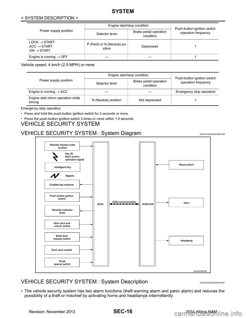
VEHICLE SECURITY SYSTEM : System DiagramINFOID:0000000009461090
VEHICLE SECURITY SYSTEM : System DescriptionINFOID:0000000009461091
• The vehicle security system has two alarm functions (theft warning alarm and panic alarm) and reduces the
possibility of a theft or mischief by activating horns and headlamps intermittently.
LOCK → START
ACC → START
ON → START P (Park) or N (Neutral) po-
sition Depressed 1
Engine is running → OFF — — 1
Power supply position
Engine start/stop condition
Push-button ignition switch
operation frequency
Selector lever Brake pedal operation
condition
Power supply position Engine start/stop condition
Push-button ignition switch
operation frequency
Selector lever Brake pedal operation
condition
Engine is running → ACC — — Emergency stop operation
Engine stall return operation while
driving N (Neutral) position Not depressed 1
ALKIA2564GB
Revision: November 20132014 Altima NAMRevision: November 20132014 Altima NAM
Page 4154 of 4801
PRECAUTIONSSTC-3
< PRECAUTION >
C
D E
F
H I
J
K L
M A
B
STC
N
O P
PRECAUTION
PRECAUTIONS
Precaution for Supplemental Restraint System (SRS) "AIR BAG" and "SEAT BELT
PRE-TENSIONER"
INFOID:0000000009951730
The Supplemental Restraint System such as “A IR BAG” and “SEAT BELT PRE-TENSIONER”, used along
with a front seat belt, helps to reduce the risk or severi ty of injury to the driver and front passenger for certain
types of collision. Information necessary to service t he system safely is included in the SR and SB section of
this Service Manual.
WARNING:
• To avoid rendering the SRS inoper ative, which could increase the risk of personal injury or death in
the event of a collision which would result in air bag inflation, all maintenance must be performed by
an authorized NISSAN/INFINITI dealer.
• Improper maintenance, including in correct removal and installation of the SRS, can lead to personal
injury caused by unintentional act ivation of the system. For removal of Spiral Cable and Air Bag
Module, see the SR section.
• Do not use electrical test equipm ent on any circuit related to the SRS unless instructed to in this
Service Manual. SRS wiring harnesses can be identi fied by yellow and/or orange harnesses or har-
ness connectors.
PRECAUTIONS WHEN USING POWER TOOLS (AIR OR ELECTRIC) AND HAMMERS
WARNING:
• When working near the Airbag Diagnosis Sensor Un it or other Airbag System sensors with the Igni-
tion ON or engine running, DO NOT use air or el ectric power tools or strike near the sensor(s) with a
hammer. Heavy vibration could activate the sensor( s) and deploy the air bag(s), possibly causing
serious injury.
• When using air or electric power tools or hammers , always switch the Ignition OFF, disconnect the
battery and wait at least three mi nutes before performing any service.
Service Notice and Precautions for Hydrau lic Pump Electric Power Steering System
INFOID:0000000009460340
• Check each tire for proper air pressure and size. Refer to WT-60, "Tire".
• Verify that the steering system components are G enuine NISSAN parts and have been installed properly.
• Check the steering column for loose mounting bolts.
• Check the steering gear assembly for loose mounting bolts. Check the inner sockets and outer sockets for
damage or wear. Inspect the boots and seals for leakage of power steering fluid.
• Verify proper wheel alignment. Refer to FSU-7, "Inspection and Adjustment"
.
• Check for any damage, wear, or modification to the suspension and body that would result in increased
weight or an improper wheelarch height. Refer to FSU-26, "Wheelarch Height (Unladen*
1)".
• Check for proper battery voltage.
• Verify that all power steering pump assembly connections are clean and fully seated.
• Verify that only Genuine NISSAN E-PSF is used. Use of any power steering fluid other than Genuine NIS-
SAN E-PSF will prevent the power st eering system from proper operation.
• An audible high pitch noise may be heard from the engine compartment when the steering wheel is oper-
ated, particularly at low speeds such as a parking lot maneuver. This condition is not a malfunction, rather
normal system operation. Steering at low speeds or parking lot maneuvers demands higher hydraulic assis-
tance, resulting in larger power st eering pump load and increased system noise.
• The power steering pump is electrically controlled by the power steering control module.
• Before connecting or disconnecting the power steeri ng control module harness connectors, turn ignition
switch “OFF” and disconnect battery ground cable. Batter y voltage is applied to power steering control mod-
ule even if ignition switch is turned “OFF”.
Revision: November 20132014 Altima NAMRevision: November 20132014 Altima NAM
Page 4207 of 4801
DIAGNOSIS AND REPAIR WORKFLOWSTR-17
< BASIC INSPECTION >
C
D E
F
G H
I
J
K L
M A
STR
NP
O
2.CHECK THAT THE STARTER MOTOR STOPS
Check that the starter motor stops after starting the engine.
Does the starter motor stop?
YES >> Inspection End.
NO >> Replace starter motor. Refer to STR-22, "QR25DE : Removal and Installation"
(QR25DE) or STR-
23, "VQ35DE : Removal and Installation" (VQ35DE).
3.CHECK THAT THE ENGINE TURNS WHEN CRANKING
Check that the engine turns when cranking.
Does engine turn when cranking?
YES >> GO TO 4.
NO >> GO TO 5.
4.CHECK THE ENGINE SPEED WHEN CRANKING
Check that the engine speed is not low when cranking.
Does engine turn normally?
YES >> Check igniti on/fuel system.
NO >> Check charge condition, corrosion and connection condition of the battery.
5.CHECK STARTER MOTOR ACTIVATION
Check that the starter motor runs at cranking.
Does starter motor turn?
YES >> Replace starter motor. Refer to STR-22, "QR25DE : Removal and Installation" (QR25DE) or STR-
23, "VQ35DE : Removal and Installation" (VQ35DE).
NO >> GO TO 6.
6.CHECK POWER SUPPLY CIRCUIT
Check the following conditions:
• Fuse and fusible link
• Charge condition, corrosion and connection of the battery.
Are these inspection results normal?
YES >> GO TO 7.
NO >> Repair as needed.
7.CHECK STARTING SYSTEM WIRING
Check the following:
• “B” terminal circuit. Refer to STR-18, "Diagnosis Procedure"
.
• “S” terminal circuit. Refer to STR-20, "Diagnosis Procedure"
.
Are the inspection results normal?
YES >> Replace starter motor. Refer to STR-22, "QR25DE : Removal and Installation" (QR25DE) or STR-
23, "VQ35DE : Removal and Installation" (VQ35DE).
NO >> Repair as needed.
Revision: November 20132014 Altima NAMRevision: November 20132014 Altima NAM
Page 4216 of 4801

TM-1
TRANSMISSION & DRIVELINE
CEF
G H
I
J
K L
M
SECTION TM
A
B
TM
N
O P
CONTENTS
TRANSAXLE & TRANSMISSION
CVT: RE0F10D
PRECAUTION ................ ...............................
9
PRECAUTIONS .............................................. .....9
Precaution for Supplemental Restraint System
(SRS) "AIR BAG" and "SEAT BELT PRE-TEN-
SIONER" ............................................................. ......
9
Precaution for Procedure without Cowl Top Cover ......9
Precaution for TCM and Transaxle Assembly Re-
placement ............................................................ ......
9
General Precautions ...............................................10
On Board Diagnosis (OBD) System of CVT and
Engine ................................................................. ....
11
Removal and Installation Procedure for CVT Unit
Connector ............................................................ ....
11
PREPARATION ...........................................13
PREPARATION .............................................. ....13
Special Service Tools .......................................... ....13
Commercial Service Tools ......................................13
SYSTEM DESCRIPTION .............................14
COMPONENT PARTS ................................... ....14
CVT CONTROL SYSTEM .........................................14
CVT CONTROL SYSTEM : Component Parts Lo-
cation ................................................................... ....
14
CVT CONTROL SYSTEM : TCM ............................16
CVT CONTROL SYSTEM : Transmission Range
Switch .................................................................. ....
16
CVT CONTROL SYSTEM : Primary Speed Sen-
sor ....................................................................... ....
16
CVT CONTROL SYSTEM : Output Speed Sensor ....16
CVT CONTROL SYSTEM : In put Speed Sensor ....17
CVT CONTROL SYSTEM : CVT Fluid Tempera-
ture Sensor .......................................................... ....
17
CVT CONTROL SYSTEM : Primary Pressure
Sensor ................................................................. ....
18
CVT CONTROL SYSTEM : Secondary Pressure
Sensor ................................................................. ....
18
CVT CONTROL SYSTEM : Primary Pressure So-
lenoid Valve ......................................................... ....
19
CVT CONTROL SYSTEM : Secondary Pressure
Solenoid Valve ..................................................... ....
19
CVT CONTROL SYSTEM : Select Solenoid Valve
....
19
CVT CONTROL SYSTEM : Torque Converter
Clutch Solenoid Valve ......................................... ....
19
CVT CONTROL SYSTEM : Line Pressure Sole-
noid Valve ............................................................ ....
20
CVT CONTROL SYSTEM : Overdrive Control
Switch .................................................................. ....
20
CVT CONTROL SYSTEM : O/D OFF Indicator
Lamp .................................................................... ....
20
CVT CONTROL SYSTEM : Shift Position Indica-
tor ........................................................................ ....
20
SHIFT LOCK SYSTEM ..............................................20
SHIFT LOCK SYSTEM : Component Parts Loca-
tion ....................................................................... ....
21
STRUCTURE AND OPERATION .....................22
TRANSAXLE .......................................................... ....22
TRANSAXLE : Cross-Sectional View ......................22
TRANSAXLE : Operation Stat us .............................23
TRANSAXLE : Transaxle Me chanism .....................23
TRANSAXLE : Oil Pressure System .......................26
TRANSAXLE : Component De scription ...................27
FLUID COOLER & FLUID WARMER SYSTEM .... ....27
FLUID COOLER & FLUID WARMER SYSTEM :
System Description .............................................. ....
28
SHIFT LOCK SYSTEM ..............................................28
SHIFT LOCK SYSTEM : Syst em Description ..........28
SYSTEM ...................... ......................................30
CVT CONTROL SYSTEM ..... .....................................30
CVT CONTROL SYSTEM : S ystem Description .....30
Revision: November 20132014 Altima NAMRevision: November 20132014 Altima NAM