stall speed NISSAN TEANA 2014 Owners Manual
[x] Cancel search | Manufacturer: NISSAN, Model Year: 2014, Model line: TEANA, Model: NISSAN TEANA 2014Pages: 4801, PDF Size: 51.2 MB
Page 2284 of 4801

EXL-18
< SYSTEM DESCRIPTION >
DIAGNOSIS SYSTEM (BCM)
HEADLAMP
HEADLAMP : CONSULT Function (BCM - HEADLAMP)INFOID:0000000009956425
CAUTION:
After disconnecting the CONSULT vehicle interface (VI) from the data link connector, the ignition must
be cycled OFF → ON (for at least 5 seconds) → OFF. If this step is not performed, the BCM may not go
to ”sleep mode”, potentially causing a di scharged battery and a no-start condition.
DATA MONITOR
ACTIVE TEST
RAP system RETAINED PWR ×
Signal buffer system SIGNAL BUFFER ×
TPMS AIR PRESSURE MONITOR ××××
System Sub System
Direct Diagnostic Mode
Ecu Identification
Self Diagnostic Result
Data Monitor
Active Test
Work support
Configuration
CAN Diag Support Mntr
Monitor Item [Unit] Description
PUSH SW [On/Off] Indicates condition of push-button ignition switch.
ENGINE STATE [STOP/STALL/CRANK/RUN] Indicates engine st atus received from ECM on CAN communication line.
VEH SPEED 1 [km/h] Indicates vehicle speed signal received from ABS on CAN communication line.
TURN SIGNAL R [On/Off]
Indicates condition of combination switch.
TURN SIGNAL L [On/Off]
TAIL LAMP SW [On/Off]
HI BEAM SW [On/Off]
HEAD LAMP SW 1 [On/Off]
HEAD LAMP SW 2 [On/Off]
PASSING SW [On/Off]
AUTO LIGHT SW [On/Off]
FR FOG SW [On/Off]
DOOR SW-DR [On/Off] Indicates condition of front door switch LH.
DOOR SW-AS [On/Off] Indicates condition of front door switch RH.
DOOR SW-RR [On/Off] Indicates condition of rear door switch RH.
DOOR SW-RL [On/Off] Indicates condition of rear door switch LH.
DOOR SW-BK [On/Off] Indicates condition of trunk switch.
OPTI SEN (DTCT) [V] Indicates outside brightness voltage signal from optical sensor.
OPTI SEN (FILT) [V] Indicates outside brightness voltage signal from optical sensor filtered by BCM.
Test Item Description
FR FOG LAMP This test is able to check front fog lamp operation [On/Off].
DAYTIME RUNNING LIGHT This test is able to check daytime running la mp operation [On/Off].
ILL DIM SIGNAL This test is able to check head lamp illumination dimming operation [On/Off].
Revision: November 20132014 Altima NAMRevision: November 20132014 Altima NAM
Page 2631 of 4801
OIL
HA-25
< PERIODIC MAINTENANCE >
C
D E
F
G H
J
K L
M A
B
HA
N
O P
OIL
DescriptionINFOID:0000000009463930
MAINTENANCE OF OIL LEVEL
The compressor oil is circulating in the system together wi th the refrigerant. It is necessary to fill compressor
with oil when replacing A/C system parts or when a large amount of refrigerant leakage is detected. It is impor-
tant to always maintain oil level within the spec ified level, otherwise the following conditions may occur:
• Insufficient oil amount: Stuck compressor
• Excessive oil amount: Insufficient coo ling (caused by insufficient heat exchange)
InspectionINFOID:0000000009463931
If a compressor is malfunctioning (internal noise, insufficient cooling), check the compressor oil.
1.COMPRESSOR OIL JUDGMENT
1. Remove the compressor. Refer to HA-30, "COMPRESSOR : Removal and Installation"
.
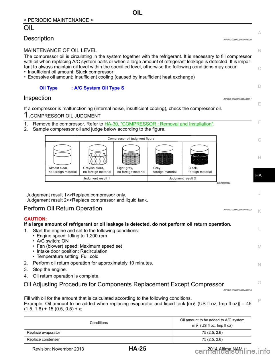
2. Sample compressor oil and judge below according to the figure.
Judgement result 1>>Replace compressor only.
Judgement result 2>>Replace compressor and liquid tank.
Perform Oil Return OperationINFOID:0000000009463932
CAUTION:
If a large amount of refrigerant or oil leakage is detected, do not perform oil return operation.
1. Start the engine and set to the following conditions: • Engine speed: Idling to 1,200 rpm
• A/C switch: ON
• Fan (blower) speed: Maximum speed set
• Intake door position: Recirculation
• Temperature setting: Full cold
2. Perform oil return operation for approximately 10 minutes.
3. Stop the engine.
4. Oil return operation is complete.
Oil Adjusting Procedure for Component s Replacement Except Compressor
INFOID:0000000009463933
Fill with oil for the amount that is calculated according to the following conditions.
Example: Oil amount to be added when replacing evaporator and liquid tank [m (US fl oz, Imp fl oz)] = 45
(1.5, 1.6) + 15 (0.5, 0.5) + α
Oil Type : A/C System Oil Type S
JSIIA0927GB
Conditions
Oil amount to be added to A/C system
m (US fl oz, Imp fl oz)
Replace evaporator 75 (2.5, 2.6)
Replace condenser 75 (2.5, 2.6)
Revision: November 20132014 Altima NAM
Page 2660 of 4801
![NISSAN TEANA 2014 Owners Manual
COMPONENT PARTSHAC-11
< SYSTEM DESCRIPTION > [AUTOMATIC AIR CONDITIONER]
C
D E
F
G H
J
K L
M A
B
HAC
N
O P
Air mix door motor RH The air mix door controls the mix of hot or cold air that enters th](/img/5/57390/w960_57390-2659.png "NISSAN TEANA 2014 Owners Manual
COMPONENT PARTSHAC-11
< SYSTEM DESCRIPTION > [AUTOMATIC AIR CONDITIONER]
C
D E
F
G H
J
K L
M A
B
HAC
N
O P
Air mix door motor RH The air mix door controls the mix of hot or cold air that enters th")
COMPONENT PARTSHAC-11
< SYSTEM DESCRIPTION > [AUTOMATIC AIR CONDITIONER]
C
D E
F
G H
J
K L
M A
B
HAC
N
O P
Air mix door motor RH The air mix door controls the mix of hot or cold air that enters the ventilation system. It is controlled
by the A/C auto amp. based on the position of the temperature dial. The air mix door motor RH re-
ceives position commands from the A/C auto amp. and reports actual door position back via an LCU
(Local Control Unit) installed inside the motor. Commands and responses are sent across the LIN (Lo-
cal Interconnect Network) to each motor simultaneously, with each motor having its own unique ad-
dress, thereby only responding to requests sent to its specific address. The LCU reads the door
position from a Position Balanced Resistor (PBR), also part of the motor, and returns that information
to the A/C auto amp. The LCU switches the polarity of the circuits connected to the DC motor to drive
the motor forward or backward as requested by the A/C auto amp. If the air mix door moves to a po-
sition less than 5% or more than 95% of its expected or allowed positions, the A/C auto amp. will set
a DTC.
Ambient sensor The ambient sensor measures the temperature of the air surrounding the vehicle. The sensor uses a
thermistor which is sensitive to the change in temperature. The electrical resistance of the thermistor
decreases as temperature increases.
BCM The BCM receives the fan ON and A/C ON signals from the A/C auto amp. and sends a compressor
ON request to the ECM.
Blower motor The blower motor varies the speed at which the air flows through the ventilation system.
ECM The ECM sends a compressor ON request to the IPDM E/R based on the status of engine operation
and load as well as refrigerant pressure information. If all the conditions are met for A/C operation,
the ECM transmits the compressor ON request to the IPDM E/R. The ECM shares the refrigerant
pressure sensor signal, engine RPM, and engine coolant temperature with the A/C auto amp. via
CAN communication line.
Front blower motor relay The front blower motor relay controls the flow of current to fuse 17 and 27 in the Fuse Block (J/B).
The relay is connected directly to ground, and is energized when the ignition switch is in the ON or
START position.
Fuse Block (J/B) Located in the passenger compartment, behind the left lower IP, the Fuse Block (J/B) contains the
front blower motor relay and several fuses required for the air conditioner control system.
Intake door motor The intake door motor controls the position of the intake door. Fresh air is allowed to enter the cabin
in one position, and recirculated inside air is allowed to enter in the other position. At times the A/C
auto amp. may command partial fresh or recirculation based on evaporator or coolant temperatures.
The intake door motor receives position commands from the A/C auto amp. and reports actual door
position back via an LCU (Local Control Unit) installed inside the motor. Commands and responses
are sent across the LIN (Local Interconnect Network) to each motor simultaneously, with each motor
having its own unique address, thereby only responding to requests sent to its specific address. The
LCU reads the door position from a Position Balanced Resistor (PBR), also part of the motor, and re-
turns that information to the A/C auto amp. The LCU switches the polarity of the circuits connected to
the DC motor to drive the motor forward or backward as requested by the A/C auto amp. If the recir-
culation door moves to a position less than 5% or more than 95% of its expected or allowed positions,
the A/C auto amp. will set a DTC.
Intake sensor The intake sensor measures the temperature of the front evaporator fins. The sensor uses a ther-
mistor which is sensitive to the change in temperature. The electrical resistance of the thermistor de-
creases as temperature increases.
In-vehicle sensor In-vehicle sensor measures temperature of intake air that flows through aspirator to passenger room.
The sensor uses a thermistor which is sensitive to the change in temperature. The electrical resis-
tance of the thermistor decreases as temperature increases.
IPDM E/R Refer to PCS-6, "RELAY CONTROL SYSTEM : System Description"
.
Mode door motor The mode door controls the direction the conditioned air passes through the ventilation system.
Through a series of levers and gears, the mode door controls the defrost door, the foot door, and the
vent door. There are 5 preset positions: VENT, B/L, FOOT, D/F, and DEF. The FOOT position can be
set to allow some airflow through to the defroster vent, or to completely block the defroster vent using
the CONSULT. The mode door motor receives position commands from the A/C auto amp. and re-
ports actual door position back via an LCU (Local Control Unit) installed inside the motor. Commands
and responses are sent across the LIN (Local Interconnect Network) to each motor simultaneously,
with each motor having its own unique address, thereby only responding to requests sent to its spe-
cific address. The LCU reads the door position from a Position Balanced Resistor (PBR), also part of
the motor, and returns that information to the A/C auto amp. The LCU switches the polarity of the cir-
cuits connected to the DC motor to drive the motor forward or backward as requested by the A/C auto
amp. The mode door has 5 expected positions and, therefore, can set up to 5 DTCs if the expected
position is not reported back to the A/C auto amp.
Component Description
Revision: November 20132014 Altima NAMRevision: November 20132014 Altima NAM
Page 2731 of 4801
![NISSAN TEANA 2014 Owners Manual
HAC-82
< DTC/CIRCUIT DIAGNOSIS >[AUTOMATIC AIR CONDITIONER]
POWER SUPPLY AND GROUND CIRCUIT
Is the inspection result normal?
YES >> GO TO 2.
NO >> GO TO 4.
2.CHECK INTAKE MODE DOOR MOTOR GROUND CIRC](/img/5/57390/w960_57390-2730.png "NISSAN TEANA 2014 Owners Manual
HAC-82
< DTC/CIRCUIT DIAGNOSIS >[AUTOMATIC AIR CONDITIONER]
POWER SUPPLY AND GROUND CIRCUIT
Is the inspection result normal?
YES >> GO TO 2.
NO >> GO TO 4.
2.CHECK INTAKE MODE DOOR MOTOR GROUND CIRC")
HAC-82
< DTC/CIRCUIT DIAGNOSIS >[AUTOMATIC AIR CONDITIONER]
POWER SUPPLY AND GROUND CIRCUIT
Is the inspection result normal?
YES >> GO TO 2.
NO >> GO TO 4.
2.CHECK INTAKE MODE DOOR MOTOR GROUND CIRCUIT
1. Turn ignition switch OFF.
2. Disconnect intake mode door motor connector.
3. Check continuity between intake mode door motor harness connector and ground.
Is the inspection result normal?
YES >> GO TO 3.
NO >> Repair harness or connector.
3.CHECK INSTALLATION OF INTAKE MODE DOOR MOTOR
Check intake mode door motor is properly installed. Refer to HAC-108, "Exploded View"
.
Is the inspection result normal?
YES >> Replace intake mode door motor. Refer to HAC-109, "INTAKE DOOR MOTOR : Removal and
Installation".
NO >> Repair or replace malfunctioning part.
4.CHECK INTAKE MODE DOOR MOTOR POWER SUPPLY CIRCUIT
1. Turn ignition switch OFF.
2. Disconnect intake mode door motor connector and A/C auto amp. connector.
3. Check continuity between intake mode door mo tor harness connector and A/C auto amp. harness con-
nector.
Is the inspection result normal?
YES >> Replace A/C auto amp. Refer to HAC-102, "Removal and Installation".
NO >> Repair harness or connector.
A/C SWITCH ASSEMBLY
A/C SWITCH ASSEMBLY : Co mponent Function CheckINFOID:0000000009463154
1.CHECK OPERATION
1. Press the AUTO switch, and then check t hat “AUTO” is shown on the display.
2. Operate the temperature control switch (driver side). Check that the fan speed or outlet changes. (The
discharge air temperature or fan speed varies depending on the ambient temperature, in-vehicle tempera-
ture, and temperature setting.)
Does it operate normally?
YES >> Inspection End.
NO >> Perform trouble diagnosis for the A/C switch assembly. Refer to HAC-83, "A/C SWITCH ASSEM-
BLY : Diagnosis Procedure".
+
−Voltage
(Approx.)
Intake mode door motor
Connector Terminal M126 1 Ground Battery voltage
Intake mode door motor —Continuity
Connector Terminal
M126 2 Ground Yes
Intake mode door motor A/C auto amp. Continuity
Connector Terminal Connector Terminal
M126 1 M152 17 Yes
Revision: November 20132014 Altima NAMRevision: November 20132014 Altima NAM
Page 2734 of 4801
![NISSAN TEANA 2014 Owners Manual
BLOWER MOTORHAC-85
< DTC/CIRCUIT DIAGNOSIS > [AUTOMATIC AIR CONDITIONER]
C
D E
F
G H
J
K L
M A
B
HAC
N
O P
1. Reconnect blower motor connector and A/C auto amp. connector.
2. Turn ignition switch](/img/5/57390/w960_57390-2733.png "NISSAN TEANA 2014 Owners Manual
BLOWER MOTORHAC-85
< DTC/CIRCUIT DIAGNOSIS > [AUTOMATIC AIR CONDITIONER]
C
D E
F
G H
J
K L
M A
B
HAC
N
O P
1. Reconnect blower motor connector and A/C auto amp. connector.
2. Turn ignition switch")
BLOWER MOTORHAC-85
< DTC/CIRCUIT DIAGNOSIS > [AUTOMATIC AIR CONDITIONER]
C
D E
F
G H
J
K L
M A
B
HAC
N
O P
1. Reconnect blower motor connector and A/C auto amp. connector.
2. Turn ignition switch ON.
3. Operate MODE switch to set air outlet to VENT.
4. Change fan speed from Lo to Hi, and check duty ratios between blower motor harness connector and
ground by using an oscilloscope.
NOTE:
Calculate drive signal duty ratio as shown in the figure.
T2 = Approx. 1.6 ms
Is the inspection result normal?
YES >> Replace blower motor. Refer to VTL-13, "BLOWER MOTOR : Removal and Installation".
NO >> Replace A/C auto amp. Refer to HAC-102, "Removal and Installation"
.
6.CHECK BLOWER MOTOR RELAY GROUND CIRCUIT
1. Turn ignition switch OFF.
2. Check continuity between fuse bl ock (J/B) harness connector and ground.
Is the inspection result normal?
YES >> GO TO 7.
NO >> Repair harness or connector.
7.CHECK FRONT BLOWER MOTOR RELAY
Check front blower motor relay. Refer to HAC-85, "Component Inspection (Front Blower Motor Relay)"
.
Is the inspection result normal?
YES >> Repair harness or connector between blower motor and fuse block (J/B).
NO >> Replace front blower motor relay.
Component Inspection (Blower Motor)INFOID:0000000009463157
1.CHECK BLOWER MOTOR
1. Connect battery voltage to terminal 1 of blower motor.
2. Connect ground to terminal 2 of blower motor.
Does the blower fan operate?
YES >> Intermittent incident. Refer to GI-43, "Intermittent Incident".
NO >> Replace blower motor. Refer to VTL-13, "BLOWER MOTOR : Removal and Installation"
.
Component Inspection (Front Blower Motor Relay)INFOID:0000000009463158
1.CHECK BLOWER RELAY
1. Turn ignition switch OFF.
2. Remove front blower motor relay.
Blower motor Condition Duty ratio
(Approx.)
Connector Terminal Fan speed (manual)
VENT mode
M31 17 1st 25 %
2nd 33 % 3rd 41 %4th 51 %
5th 61 %
6th 69 %
7th 81 %
JPLIA1210GB
Fuse block (J/B) —Continuity
Connector Terminal
M4 13R Ground Yes
Revision: November 20132014 Altima NAMRevision: November 20132014 Altima NAM
Page 2764 of 4801
![NISSAN TEANA 2014 Owners Manual
COMPONENT PARTSHAC-115
< SYSTEM DESCRIPTION > [MANUAL AIR CONDITIONER]
C
D E
F
G H
J
K L
M A
B
HAC
N
O P
Component DescriptionINFOID:0000000009463193
7. Refrigerant pressure sensor (view with fron](/img/5/57390/w960_57390-2763.png "NISSAN TEANA 2014 Owners Manual
COMPONENT PARTSHAC-115
< SYSTEM DESCRIPTION > [MANUAL AIR CONDITIONER]
C
D E
F
G H
J
K L
M A
B
HAC
N
O P
Component DescriptionINFOID:0000000009463193
7. Refrigerant pressure sensor (view with fron")
COMPONENT PARTSHAC-115
< SYSTEM DESCRIPTION > [MANUAL AIR CONDITIONER]
C
D E
F
G H
J
K L
M A
B
HAC
N
O P
Component DescriptionINFOID:0000000009463193
7. Refrigerant pressure sensor (view with front bumper fascia removed) 8. Blower motor (view with front air con-
ditioning assembly removed from ve-
hicle) 9. Intake door motor
10. Mode door motor 11. Air mix door motor
Component Description
A/C Compressor Vaporized refrigerant is drawn into the A/C compressor from the evaporator, where it is compressed
to a high pressure, high temperature vapor. The hot, compressed vapor is then discharged to the con-
denser.
Air mix door motor The air mix door controls the mix of hot or cold air that enters the ventilation system. It is controlled
by the front air control based on the position of the temperature dial. The air mix door motor receives
position commands from the front air control and reports actual door position back via an LCU (Local
Control Unit) installed inside the motor. Commands and responses are sent across the LIN (Local In-
terconnect Network) to each motor simultaneously, with each motor having its own unique address,
thereby only responding to requests sent to its specific address. The LCU reads the door position from
a Position Balanced Resistor (PBR), also part of the motor, and returns that information to the front
air control. The LCU switches the polarity of the circuits connected to the DC motor to drive the motor
forward or backward as requested by the front air control.
BCM The BCM receives the fan ON and A/C ON signals from the front air control and sends a compressor
ON request to the ECM.
Blower motor The blower motor varies the speed at which the air flows through the ventilation system.
ECM The ECM sends a compressor ON request to the IPDM E/R based on the status of engine operation
and load as well as refrigerant pressure information. If all the conditions are met for A/C operation,
the ECM transmits the compressor ON request to the IPDM E/R. The ECM shares the refrigerant
pressure sensor signal, engine RPM, and engine coolant temperature with the front air control via
CAN communication line.
Front air control The front air control controls the operation of the A/C and heating system based on inputs from the
temperature control knob, the mode switches, the blower control dial, and inputs received from the
ECM and combination meter across the CAN.
Front blower motor relay The front blower motor relay controls the flow of current to fuses 17 and 27 in the Fuse Block (J/B).
The relay is connected directly to ground, and is energized when the ignition switch is in the ON or
START position.
Fuse Block (J/B) Located in the passenger compartment, behind the left lower IP, the Fuse Block (J/B) contains the
front blower motor relay and several fuses required for the air conditioner control system.
Intake door motor The intake door motor controls the position of the intake door. Fresh air is allowed to enter the cabin
in one position, and recirculated inside air is allowed to enter in the other position. At times the front
air control may command partial fresh or recirculation based on evaporator or coolant temperatures.
The intake door motor receives position commands from the front air control and reports actual door
position back via an LCU (Local Control Unit) installed inside the motor. Commands and responses
are sent across the LIN (Local Interconnect Network) to each motor simultaneously, with each motor
having its own unique address, thereby only responding to requests sent to its specific address. The
LCU reads the door position from a Position Balanced Resistor (PBR), also part of the motor, and re-
turns that information to the front air control. The LCU switches the polarity of the circuits connected
to the DC motor to drive the motor forward or backward as requested by the front air control.
IPDM E/R Refer to PCS-6, "RELAY CONTROL SYSTEM : System Description"
.
Revision: November 20132014 Altima NAMRevision: November 20132014 Altima NAM
Page 2798 of 4801
![NISSAN TEANA 2014 Owners Manual
BLOWER MOTORHAC-149
< DTC/CIRCUIT DIAGNOSIS > [MANUAL AIR CONDITIONER]
C
D E
F
G H
J
K L
M A
B
HAC
N
O P
1. Reconnect blower motor connector and front air control connector.
2. Turn ignition swit](/img/5/57390/w960_57390-2797.png "NISSAN TEANA 2014 Owners Manual
BLOWER MOTORHAC-149
< DTC/CIRCUIT DIAGNOSIS > [MANUAL AIR CONDITIONER]
C
D E
F
G H
J
K L
M A
B
HAC
N
O P
1. Reconnect blower motor connector and front air control connector.
2. Turn ignition swit")
BLOWER MOTORHAC-149
< DTC/CIRCUIT DIAGNOSIS > [MANUAL AIR CONDITIONER]
C
D E
F
G H
J
K L
M A
B
HAC
N
O P
1. Reconnect blower motor connector and front air control connector.
2. Turn ignition switch ON.
3. Operate MODE switch to set air outlet to VENT.
4. Change fan speed from Lo to Hi, and check duty ratios between blower motor harness connector and
ground by using an oscilloscope.
NOTE:
Calculate drive signal duty ratio as shown in the figure.
T2 = Approx. 1.6 ms
Is the inspection result normal?
YES >> Replace blower motor. Refer to VTL-13, "BLOWER MOTOR : Removal and Installation".
NO >> Replace front air control. Refer to HAC-102, "Removal and Installation"
.
6.CHECK BLOWER MOTOR RELAY GROUND CIRCUIT
1. Turn ignition switch OFF.
2. Check continuity between fuse bl ock (J/B) harness connector and ground.
Is the inspection result normal?
YES >> GO TO 7.
NO >> Repair harness or connector.
7.CHECK FRONT BLOWER MOTOR RELAY
Check front blower motor relay. Refer to HAC-149, "Component Inspection (Front Blower Motor Relay)"
.
Is the inspection result normal?
YES >> Repair harness or connector between blower motor and fuse block (J/B).
NO >> Replace front blower motor relay.
Component Inspection (Blower Motor)INFOID:0000000009463215
1.CHECK BLOWER MOTOR
1. Connect battery voltage to terminal 1 of blower motor.
2. Connect ground to terminal 2 of blower motor.
Does the blower fan operate?
YES >> Intermittent incident. Refer to GI-43, "Intermittent Incident".
NO >> Replace blower motor. Refer to VTL-13, "BLOWER MOTOR : Removal and Installation"
.
Component Inspection (Front Blower Motor Relay)INFOID:0000000009463216
1.CHECK BLOWER RELAY
1. Turn ignition switch OFF.
2. Remove front blower motor relay.
Blower motor Condition Duty ratio
(Approx.)
Connector Terminal Fan speed (manual)
VENT mode
M31 17 1st 25 %
2nd 33 % 3rd 41 %4th 51 %
5th 61 %
6th 69 %
7th 81 %
JPLIA1210GB
Fuse block (J/B) —Continuity
Connector Terminal
M4 13R Ground Yes
Revision: November 20132014 Altima NAMRevision: November 20132014 Altima NAM
Page 3189 of 4801
GENERAL MAINTENANCEMA-5
< PERIODIC MAINTENANCE >
C
D E
F
G H
I
J
K L
M B
MA
N
O A
PERIODIC MAINTENANCE
GENERAL MAINTENANCE
FOR USA AND CANADA
FOR USA AND CANADA : Explana
tion of General MaintenanceINFOID:0000000009464530
General maintenance includes those items which shoul d be checked during the normal day-to-day operation
of the vehicle. They are essential if the vehicle is to continue operating properly. The owners can perform
checks and inspections themselves or have their NISSAN dealers do them.
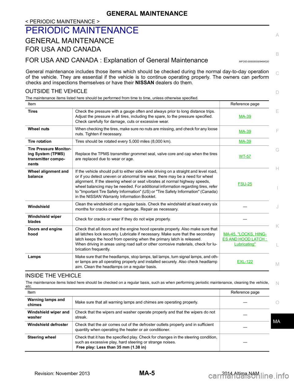
OUTSIDE THE VEHICLE
The maintenance items listed here should be performed from time to time, unless otherwise specified.
INSIDE THE VEHICLE
The maintenance items listed here should be checked on a regular basis, such as when performing periodic maintenance, cleaning the vehicle,
etc.
Item Reference page
Tires Check the pressure with a gauge often and always prior to long distance trips.
Adjust the pressure in all tires, including the spare, to the pressure specified.
Check carefully for damage, cuts or excessive wear. MA-39
Wheel nuts
When checking the tires, make sure no nuts are missing, and check for any loose
nuts. Tighten if necessary. MA-39
Tire rotation
Tires should be rotated every 5,000 miles (8,000 km). MA-39
Tire Pressure Monitor-
ing System (TPMS)
transmitter compo-
nents Replace the TPMS transmitter grommet seal, valve core and cap when the tires
are replaced due to wear or age. WT-57
Wheel alignment and
balance If the vehicle should pull to either side while driving on a straight and level road,
or if you detect uneven or abnormal tire wear, there may be a need for wheel
alignment. If the steering wheel or seat vibrates at normal highway speeds,
wheel balancing may be needed. For additional information regarding tires, refer
to "Important Tire Safety Information" (US) or "Tire Safety Information" (Canada)
in the NISSAN Warranty Information Booklet. FSU-25
Windshield
Clean the windshield on a regular basis. Check the windshield at least every six
months for cracks or other damage. Repair as necessary. —
Windshield wiper
blades Check for cracks or wear if they do not wipe properly. —
Doors and engine
hood Check that all doors and the engine hood operate properly. Also make sure that
all latches lock securely. Lubricate if necessary. Make sure that the secondary
latch keeps the hood from opening when the primary latch is released.
When driving in areas using road salt or other corrosive materials, check for lu-
brication frequently. MA-45, "LOCKS, HING-
ES AND HOOD LATCH :
Lubricating"
Lamps
Make sure that the headlamps, stop lamps, tail lamps, turn signal lamps, and oth-
er lamps are all operating properly and installed securely. Also check headlamp
aim. Clean the headlamps on a regular basis. EXL-122
Item
Reference page
Warning lamps and
chimes Make sure that all warning lamps and chimes are operating properly. —
Windshield wiper and
washer Check that the wipers and washer operate properly and that the wipers do not
streak. —
Windshield defroster Check that the air comes out of the defroster outlets properly and in sufficient
quantity when operating the heater or air conditioner. —
Steering wheel Check that it has the specified play. Check for changes in the steering condition,
such as excessive play, hard steering or strange noises.
Free play: Less than 35 mm (1.38 in) —
Revision: November 20132014 Altima NAM
Page 3218 of 4801
MA-34
< PERIODIC MAINTENANCE >
CHASSIS AND BODY MAINTENANCE
34. Select “Data Monitor” in “TRANSMISSION” using CONSULT.
35. Select “CONFORM CVTF DETERIORTN”.
36. Select “Erase”.
37. Stop the engine.
CVT FLUID : AdjustmentINFOID:0000000009464569
CAUTION:
• During adjustment of the CVT fluid level, check CO NSULT so that the oil temperature may be main-
tained from 35 to 45 °C (95 to 113 °F).
• During adjustment of the CVT fluid level, check that the engine speed is maintaining 500 rpm.
• Use caution when looking into the drain hole as th ere is a risk of dripping fluid entering the eye.
1. Check that the selector lever is in the “P ” position, then completely engage the parking brake.
2. Start the engine.
3. Adjust the CVT fluid temperature to be approximately 40 °C (104 °F).
NOTE:
The CVT fluid is largely affected by temperature. Therefore be sure to use CONSULT and check the
“FLUID TEMP” under “TRANSMISSION” in “Data Monitor” while adjusting.
4. While depressing the brake pedal, shift the selector lever to the entire position from “P” to “DS”, and shift it to the “P” position.
NOTE:
Hold the lever at each position for 5 seconds.
5. Lift up the vehicle.
6. Check that there is no CVT fluid leakage.
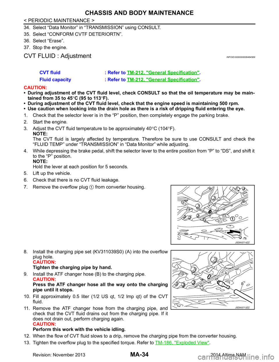
7. Remove the overflow plug from converter housing.
8. Install the charging pipe set (KV311039S0) (A) into the overflow plug hole.
CAUTION:
Tighten the charging pipe by hand.
9. Install the ATF changer hose (B) to the charging pipe. CAUTION:
Press the ATF changer hose all the way onto the charging
pipe until it stops.
10. Fill approximately 0.5 liter (1/2 US qt, 1/2 lmp qt) of the CVT
fluid.
11. Remove the ATF changer hose from the charging pipe, and check that the CVT fluid drains out from the charging pipe. If it
does not drain out, perform charging again.
CAUTION:
Perform this work with the vehicle idling.
12. When the flow of CVT fluid slows to a drip, re move the charging pipe from the converter housing.
13. Tighten the overflow plug to the specified torque. Refer to TM-186, "Exploded View"
.
CVT fluid : Refer to
TM-212, "General Specification"
.
Fluid capacity : Refer to TM-212, "General Specification"
.
JSDIA3714ZZ
JSDIA3713ZZ
Revision: November 20132014 Altima NAM
Page 3221 of 4801
CHASSIS AND BODY MAINTENANCEMA-37
< PERIODIC MAINTENANCE >
C
D E
F
G H
I
J
K L
M B
MA
N
O A
34. Select “Data Monitor” in “TRANSMISSION” using CONSULT.
35. Select “CONFORM CVTF DETERIORTN”.
36. Select “Erase”.
37. Stop the engine.
CVT FLUID : AdjustmentINFOID:0000000009464573
CAUTION:
• During adjustment of the CVT fluid level, check CO NSULT so that the oil temperature may be main-
tained from 35 to 45 °C (95 to 113 °F).
• During adjustment of the CVT fluid level, check that the engine speed is maintaining 500 rpm.
• Use caution when looking into the drain hole as there is a risk of dripping fluid entering the eye.
1. Check that the selector lever is in the “P ” position, then completely engage the parking brake.
2. Start the engine.
3. Adjust the CVT fluid temperature to be approximately 40 °C (104 °F).
NOTE:
The CVT fluid is largely affected by temperature. Therefore be sure to use CONSULT and check the
“FLUID TEMP” under “TRA NSMISSION” in “Data Monitor” while adjusting.
4. While depressing the brake pedal, shift the selector leve r to the entire position from “P” to “DS”, and shift it
to the “P” position.
NOTE:
Hold the lever at each position for 5 seconds.
5. Lift up the vehicle.
6. Check that there is no CVT fluid leakage.
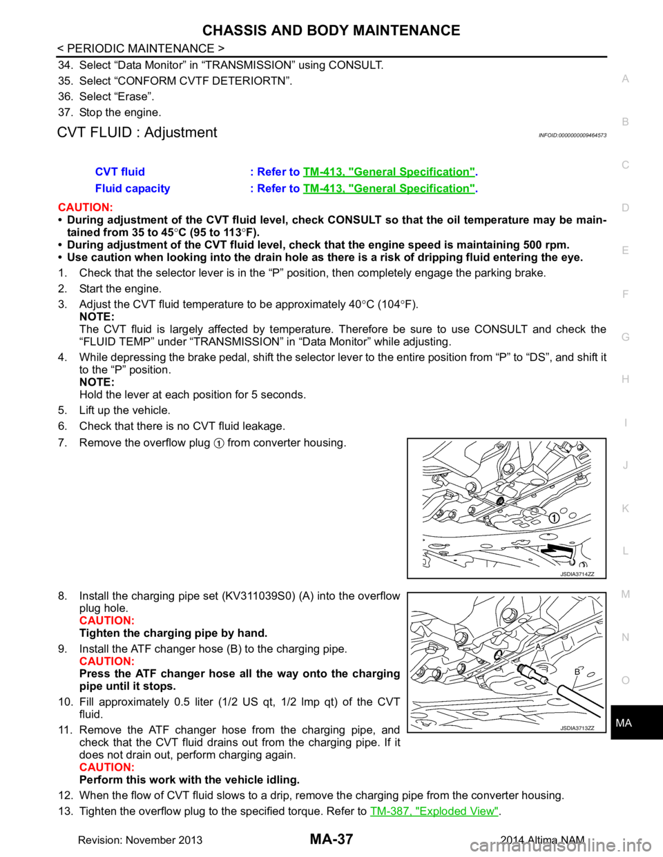
7. Remove the overflow plug from converter housing.
8. Install the charging pipe set (KV311039S0) (A) into the overflow plug hole.
CAUTION:
Tighten the charging pipe by hand.
9. Install the ATF changer hose (B) to the charging pipe. CAUTION:
Press the ATF changer hose all the way onto the charging
pipe until it stops.
10. Fill approximately 0.5 liter (1/2 US qt, 1/2 lmp qt) of the CVT
fluid.
11. Remove the ATF changer hose from the charging pipe, and check that the CVT fluid drains out from the charging pipe. If it
does not drain out, perform charging again.
CAUTION:
Perform this work with the vehicle idling.
12. When the flow of CVT fluid slows to a drip, re move the charging pipe from the converter housing.
13. Tighten the overflow plug to the specified torque. Refer to TM-387, "Exploded View"
.
CVT fluid : Refer to
TM-413, "General Specification"
.
Fluid capacity : Refer to TM-413, "General Specification"
.
JSDIA3714ZZ
JSDIA3713ZZ
Revision: November 20132014 Altima NAM