Heater NISSAN TEANA 2014 Service Manual
[x] Cancel search | Manufacturer: NISSAN, Model Year: 2014, Model line: TEANA, Model: NISSAN TEANA 2014Pages: 4801, PDF Size: 51.2 MB
Page 4135 of 4801
ST-32
< REMOVAL AND INSTALLATION >
STEERING WHEEL
• Ensure tick mark on steering wheel is aligned with tick mark on the steering column pin.
• Ensure spiral cable location pin (white rubber pin) is aligned to the steering wheel locating pin hole.
• Route driver airbag module connector(s) and steer ing wheel heater connector harnesses through the
steering wheel.
3. Connect steering wheel switch connector to spiral cable.
4. Connect steering wheel heater connector (from spiral cable) to connector on steering wheel (if equipped).
5. Insert steering wheel heater harness into hook part of the steering wheel back cover.
Revision: November 20132014 Altima NAMRevision: November 20132014 Altima NAM
Page 4220 of 4801
TM-5
CEF
G H
I
J
K L
M A
B
TM
N
O P
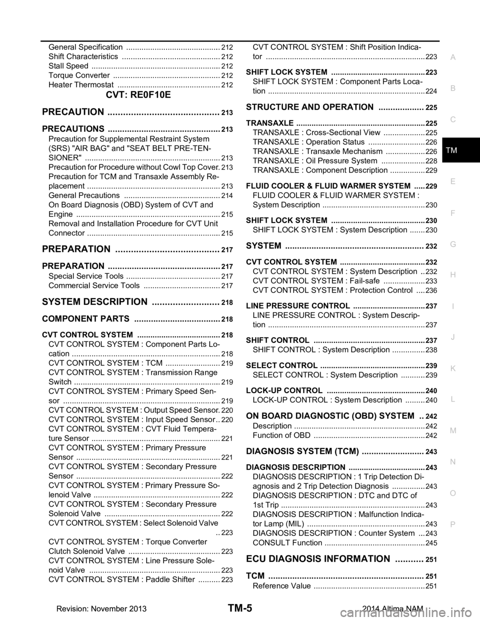
General Specification ..........................................
..
212
Shift Characteristics ..............................................212
Stall Speed ............................................................212
Torque Converter ..................................................212
Heater Thermostat ................................................212
CVT: RE0F10E
PRECAUTION ................ ............................
213
PRECAUTIONS .............................................. ..213
Precaution for Supplemental Restraint System
(SRS) "AIR BAG" and "SEAT BELT PRE-TEN-
SIONER" ............................................................. ..
213
Precaution for Procedure without Cowl Top Cover ..213
Precaution for TCM and Transaxle Assembly Re-
placement ............................................................ ..
213
General Precautions .............................................214
On Board Diagnosis (OBD) System of CVT and
Engine ................................................................. ..
215
Removal and Installation Procedure for CVT Unit
Connector ............................................................ ..
215
PREPARATION .........................................217
PREPARATION .............................................. ..217
Special Service Tools .......................................... ..217
Commercial Service Tools ....................................217
SYSTEM DESCRIPTION ...........................218
COMPONENT PARTS ................................... ..218
CVT CONTROL SYSTEM .......................................218
CVT CONTROL SYSTEM : Component Parts Lo-
cation ................................................................... ..
218
CVT CONTROL SYSTEM : TCM ..........................219
CVT CONTROL SYSTEM : Transmission Range
Switch .................................................................. ..
219
CVT CONTROL SYSTEM : Primary Speed Sen-
sor ....................................................................... ..
219
CVT CONTROL SYSTEM : Output Speed Sensor ..220
CVT CONTROL SYSTEM : Input Speed Sensor ..220
CVT CONTROL SYSTEM : CVT Fluid Tempera-
ture Sensor .......................................................... ..
221
CVT CONTROL SYSTEM : Primary Pressure
Sensor ................................................................. ..
221
CVT CONTROL SYSTEM : Secondary Pressure
Sensor ................................................................. ..
222
CVT CONTROL SYSTEM : Primary Pressure So-
lenoid Valve ......................................................... ..
222
CVT CONTROL SYSTEM : Secondary Pressure
Solenoid Valve .................................................... ..
222
CVT CONTROL SYSTEM : Select Solenoid Valve
..
223
CVT CONTROL SYSTEM : Torque Converter
Clutch Solenoid Valve ......................................... ..
223
CVT CONTROL SYSTEM : Line Pressure Sole-
noid Valve ........................................................... ..
223
CVT CONTROL SYSTEM : Paddle Shifter ...........223
CVT CONTROL SYSTEM : Shift Position Indica-
tor ........................................................................ ..
223
SHIFT LOCK SYSTEM ............................................223
SHIFT LOCK SYSTEM : Component Parts Loca-
tion ....................................................................... ..
224
STRUCTURE AND OPERATION ...................225
TRANSAXLE .......................................................... ..225
TRANSAXLE : Cross-Sectional View ....................225
TRANSAXLE : Operation Stat us ...........................226
TRANSAXLE : Transaxle Me chanism ...................226
TRANSAXLE : Oil Pressure System .....................228
TRANSAXLE : Component De scription .................229
FLUID COOLER & FLUID WARMER SYSTEM .... ..229
FLUID COOLER & FLUID WARMER SYSTEM :
System Description .............................................. ..
230
SHIFT LOCK SYSTEM ............................................230
SHIFT LOCK SYSTEM : Syst em Description ........230
SYSTEM ...................... ....................................232
CVT CONTROL SYSTEM ..... ...................................232
CVT CONTROL SYSTEM : S ystem Description ...232
CVT CONTROL SYSTEM : Fa il-safe ....................233
CVT CONTROL SYSTEM : Pr otection Control .....236
LINE PRESSURE CONTROL ......................... .........237
LINE PRESSURE CONTROL : System Descrip-
tion ....................................................................... ..
237
SHIFT CONTROL .................................................. ..237
SHIFT CONTROL : System Description ................238
SELECT CONTROL ............................................... ..239
SELECT CONTROL : System Description ............239
LOCK-UP CONTROL ............................................ ..240
LOCK-UP CONTROL : System Description ..........240
ON BOARD DIAGNOSTIC (OBD) SYSTEM ..242
Description .............................................................242
Function of OBD ....................................................242
DIAGNOSIS SYSTEM (TCM) ..........................243
DIAGNOSIS DESCRIPTION .................................. ..243
DIAGNOSIS DESCRIPTION : 1 Trip Detection Di-
agnosis and 2 Trip Detection Diagnosis .............. ..
243
DIAGNOSIS DESCRIPTION : DTC and DTC of
1st Trip ................................................................. ..
243
DIAGNOSIS DESCRIPTION : Malfunction Indica-
tor Lamp (MIL) ..................................................... ..
243
DIAGNOSIS DESCRIPTION : Counter System ....243
CONSULT Function ............................................. ..245
ECU DIAGNOSIS INFORMATION ............251
TCM .................................................................251
Reference Value .................................................. ..251
Revision: November 20132014 Altima NAMRevision: November 20132014 Altima NAM
Page 4223 of 4801
TM-8
Exploded View .......................................................382
Removal and Installation .......................................382
TCM ..................................................................384
Exploded View ..................................................... ..384
Removal and Installation .......................................384
Adjustment .............................................................385
AIR BREATHER HOSE ...................................386
Removal and Installation ..................................... ..386
CONTROL VALVE ...........................................387
Exploded View ..................................................... ..387
Removal and Installation .......................................388
Inspection ..............................................................392
INPUT SPEED SENSOR .................................393
Exploded View ..................................................... ..393
Removal and Installation .......................................393
Inspection and Adjustment ....................................393
PRIMARY SPEED SENSOR ...........................395
Exploded View ..................................................... ..395
Removal and Installation .......................................395
Inspection and Adjustment ....................................395
OUTPUT SPEED SENSOR .............................397
Exploded View ..................................................... ..397
Removal and Installation .......................................397
Inspection and Adjustment ....................................397
DIFFERENTIAL SIDE OIL SEAL ....................398
Exploded View ..................................................... ..398
Removal and Installation .......................................398
Inspection and Adjustment ....................................399
CVT OIL WARMER SYSTEM ..........................400
WATER HOSE ....................................................... ..400
WATER HOSE : Exploded View ............................400
WATER HOSE : Removal and Installation ............400
WATER HOSE : Inspection ...................................402
CVT FLUID COOLER HOSE ................................. ..402
CVT FLUID COOLER HOSE : Exploded View .....402
CVT FLUID COOLER HOSE : Removal and In-
stallation ............................................................... .
403
CVT FLUID COOLER HOSE : Inspection .............404
CVT OIL WARMER ................................................ .404
CVT OIL WARMER : Exploded View ....................404
CVT OIL WARMER : Removal and Installation ....404
CVT OIL WARMER : Inspection .......................... .405
PLUG ................................................................406
Description ........................................................... .406
Exploded View ......................................................406
Removal and Installation .......................................406
Inspection and Adjustment ................................... .406
UNIT REMOVAL AND INSTALLATION ...407
TRANSAXLE ASSEMBLY ............................. ..407
Exploded View ..................................................... .407
Removal and Installation .......................................407
Inspection and Adjustment ................................... .409
UNIT DISASSEMBLY AND ASSEMBLY ..410
TORQUE CONVERTER AND CONVERTER
HOUSING OIL SEAL ...................................... ..
410
Exploded View ..................................................... .410
Disassembly ..........................................................410
Assembly ..............................................................410
Inspection ..............................................................411
SERVICE DATA AND SPECIFICATIONS
(SDS) ............... ..........................................
413
SERVICE DATA AND SPECIFICATIONS
(SDS) .............................................................. ..
413
General Specification ........................................... .413
Shift Characteristics ..............................................413
Stall Speed ........................................................... .413
Torque Converter ..................................................413
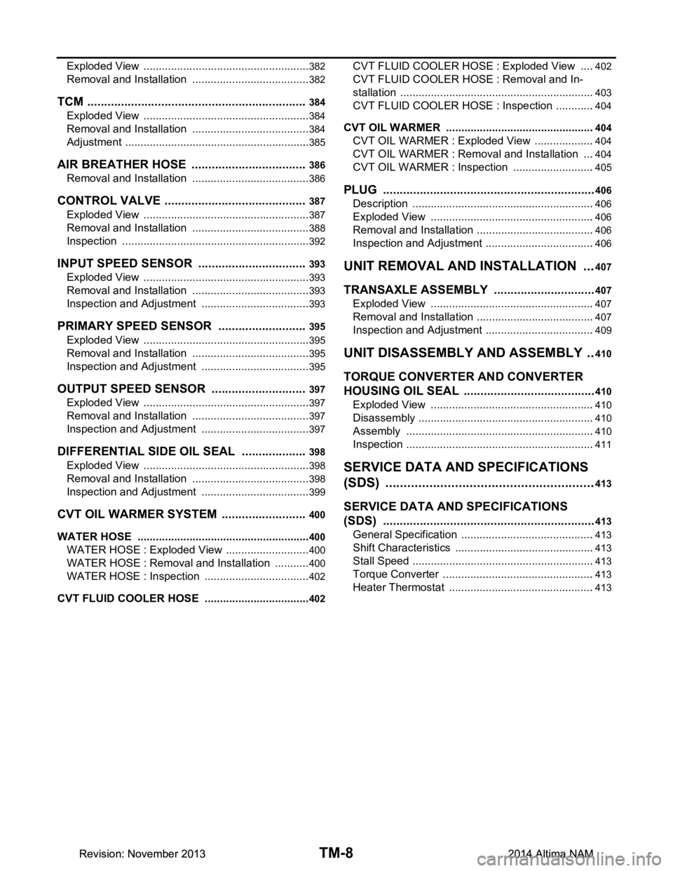
Heater Thermostat ................................................413
Revision: November 20132014 Altima NAMRevision: November 20132014 Altima NAM
Page 4243 of 4801

TM-28
< SYSTEM DESCRIPTION >[CVT: RE0F10D]
STRUCTURE AND OPERATION
FLUID COOLER & FLUID WARMER SYSTEM : System Description
INFOID:0000000009463985
CVT FLUID COOLER SCHEMATIC
COMPONENT DESCRIPTION
CVT Oil Warmer
• The CVT oil warmer (1) is installed on the front part of transaxle
assembly.
• When engine is started while engine and CVT are cold, engine coolant temperature rises more quickly than CVT fluid tempera-
ture. CVT oil warmer is provided with two circuits for CVT and
engine coolant respectively so that warmed engine coolant warms
CVT quickly. This helps shorten CVT warming up time, improving
fuel economy.
• A cooling effect is obtained when CVT fluid temperature is high.
Heater Thermostat
• The heater thermostat (1) is insta lled on the front part of transaxle
assembly.
• The heater thermostat open and close with set temperature.
SHIFT LOCK SYSTEM
SHIFT LOCK SYSTEM : System DescriptionINFOID:0000000009463986
The shift lever cannot be shifted from the “P” positi on unless the brake pedal is depressed while the ignition
switch is set to ON. The shift lock is unlocked by turn ing the shift lock solenoid ON when the ignition switch is
set to ON, the park position switch is turned ON (selec tor lever is in “P” position), and the stop lamp switch is
turned ON (brake pedal is depressed) as shown in the oper ation chart in the figure. Therefore, the shift lock
solenoid receives no ON signal and the shift lock remains locked if all of the above conditions are not fulfilled.
However, selector operation is allowed if the shift lock release button is pressed.
JSDIA3787GB
JSDIA2280ZZ
JSDIA2585ZZ
Revision: November 20132014 Altima NAMRevision: November 20132014 Altima NAM
Page 4414 of 4801

CVT OIL WARMER SYSTEMTM-199
< REMOVAL AND INSTALLATION > [CVT: RE0F10D]
C
EF
G H
I
J
K L
M A
B
TM
N
O P
CVT OIL WARMER SYSTEM
WATER HOSE
WATER HOSE : Exploded ViewINFOID:0000000009464145
WATER HOSE : Removal and InstallationINFOID:0000000009464146
REMOVAL
WARNING:
Do not remove the radiator cap when the engine is hot. Serious burns could occur from high pressure
coolant escaping from the radiator. Wrap a thick cloth around the cap. Slowly turn it a quarter turn to
allow built-up pressure to escap e. Carefully remove the cap by turning it all the way.
CAUTION:
Perform when the engine is cold.
NOTE:
When removing components such as hoses, tubes/lines, etc. , cap or plug openings to prevent fluid from spill-
ing.
1. Remove front under cover. Refer to EXT-28, "Removal and Installation"
.
Hose clamp CVT water hose A CVT oil warmer
CVT water hose B Heater thermostat CVT water hose C
Transaxle assembly
Water outlet
: Always replace after every disassembly.
: N·m (kg-m, ft-lb)
JSDIA3627GB
Revision: November 20132014 Altima NAMRevision: November 20132014 Altima NAM
Page 4415 of 4801

TM-200
< REMOVAL AND INSTALLATION >[CVT: RE0F10D]
CVT OIL WARMER SYSTEM
2. Remove engine room cover. Refer to
EM-28, "Removal and Installation".
3. Remove front air duct and air cleaner case assembly. Refer to EM-29, "Removal and Installation"
.
4. Release clip (A) and release hose clamps and remove CVT water hose A from water outlet. CAUTION:
Do not reuse hose clamps.
5. Remove CVT heater thermostat bolt, release hose clamps then remove CVT heater thermostat and CVT
water hose C from water outlet.
CAUTION:
Do not reuse hose clamps.
6. Remove CVT water hose inlet and CVT water hose outlet from CVT oil warmer.
INSTALLATION
Installation is in the reverse order of removal.
CAUTION:
Do not reuse hose clamps.
• Insert CVT water hose according to dimension (A).
• Install hose clamps (1) at both ends of CVT water hose (2) with dimension (A) from the hose end.
• Hose clamp should not interfere with the bulge.
: Front
ALDIA0364ZZ
CVT water hose (1) Insert side tube (2) Dimension (A)
CVT water hose A Water outlet
End reaches the spool portion (B)
CVT oil warmer
CVT water hose B CVT oil warmer
Heater thermostat
CVT water hose C Heater thermostat
Water outlet
JSDIA1291ZZ
Dimension (A) : 5 – 7 mm (0.20 – 0.28 in)
SCIA8123E
CVT water hose Hose end Paint mark
Position of hose clamp*
CVT water hose AWater outlet side Facing upward C
CVT oil warmer side Facing to the front of the vehicle C
CVT water hose B CVT oil warmer side Facing to the front of the vehicle B
Heater thermostat side N/A A
Revision: November 20132014 Altima NAMRevision: November 20132014 Altima NAM
Page 4416 of 4801

CVT OIL WARMER SYSTEMTM-201
< REMOVAL AND INSTALLATION > [CVT: RE0F10D]
C
EF
G H
I
J
K L
M A
B
TM
N
O P
*: Refer to the illustrations for the specific position of each hose clamp tab.
• The illustrations indicate the view from the hose ends.
• When installing hose clamps the center line of each clamp tab should be positioned as shown.
WATER HOSE : InspectionINFOID:0000000009464147
INSPECTION AFTER INSTALLATION
Start and warm up the engine. Visually check that there is no leakage of engine coolant and CVT fluid.
CVT FLUID COOLER HOSE
CVT FLUID COOLER HO SE : Exploded ViewINFOID:0000000009464148
COMPONENT PARTS LOCATION
United States and Canada
CVT water hose C Heater thermostat side N/A A
Water outlet side Facing upward C
CVT water hose Hose
end Paint mark
Position of hose clamp
*
(D): Vehicle front
(E) : Vehicle upper
JSDIA1292ZZ
JSDIA3628ZZ
Revision: November 20132014 Altima NAMRevision: November 20132014 Altima NAM
Page 4427 of 4801

TM-212
< SERVICE DATA AND SPECIFICATIONS (SDS) [CVT: RE0F10D]
SERVICE DATA AND SPECIFICATIONS (SDS)
SERVICE DATA AND SPECIFICATIONS (SDS)
SERVICE DATA AND SPECIFICATIONS (SDS)
General SpecificationINFOID:0000000009464167
*1: Refer to
MA-11, "FOR USA AND CANADA : Fluids and Lubricants".
*2: The CVT fluid capacity is the reference value.
Shift CharacteristicsINFOID:0000000009464168
Unit: rpm
CAUTION:
Lock-up is engaged at th e vehicle speed of approximately 18 km/h (12 MPH) to 40 km/h (24 MPH).
Stall SpeedINFOID:0000000009464169
Torque ConverterINFOID:0000000009464170
Unit: mm (in)
Heater ThermostatINFOID:0000000009464171
Standard
Reference value
Applied model Engine QR25DE
Axle 2WD
Transaxle model RE0F10D
Transaxle gear ratio D position 2.648 – 0.380
R position 0.745
Final drive 4.828
Recommended fluid Genuine NISSAN CVT Fluid NS-3
*1
Fluid capacity liter (US qt, Imp qt) Approx. 7.4 (7-7/8, 6-1/2)*2
CAUTION:
• Use only Genuine NISSAN CVT Fluid NS-3. Never mix with other fluid.
• Using CVT fluid other than Genuine NISSAN CVT Fluid NS-3 will deteriorate in driveability and CVT durability, and may dam-
age the CVT, which is not covered by the NISSAN new vehicle limited warranty.
Throttle position Shift pattern Engine speed
At 40 km/h (25 MPH) At 60 km/h (37 MPH)
2/8 “D” position 1,490 – 1,650 1,570 – 1,740
“D” position (O/D OFF condition) 2,950 – 3,260 3,040 – 3,360
8/8 “D” position 3,900 – 4,310 5,230 – 5,780
“D” position (O/D OFF condition) 3,520 – 3,890 4,280 – 4,730
Stall speed 2,290 – 2,520 rpm
Distance “A” between the converter housing and torque converter 14.4 (0.567)
Va l v e l i f tMore than 5.0 mm (0.197 in)
Valve opening temperature 71 °C (160 °F)
Minimum valve lift 5.0 mm/85 °C (0.197 in/203 °F)
Revision: November 20132014 Altima NAMRevision: November 20132014 Altima NAM
Page 4445 of 4801

TM-230
< SYSTEM DESCRIPTION >[CVT: RE0F10E]
STRUCTURE AND OPERATION
FLUID COOLER & FLUID WARMER SYSTEM : System Description
INFOID:0000000009464202
CVT FLUID COOLER SCHEMATIC
COMPONENT DESCRIPTION
CVT Oil Warmer
• The CVT oil warmer (1) is installed on the front part of transaxle
assembly.
• When engine is started while engine and CVT are cold, engine coolant temperature rises more quickly than CVT fluid tempera-
ture. CVT oil warmer is provided with two circuits for CVT and
engine coolant respectively so that warmed engine coolant warms
CVT quickly. This helps shorten CVT warming up time, improving
fuel economy.
• A cooling effect is obtained when CVT fluid temperature is high.
Heater Thermostat
• The heater thermostat (1) is insta lled on the front part of transaxle
assembly.
• The heater thermostat open and close with set temperature.
SHIFT LOCK SYSTEM
SHIFT LOCK SYSTEM : System DescriptionINFOID:0000000009464203
The shift lever cannot be shifted from the “P” positi on unless the brake pedal is depressed while the ignition
switch is set to ON. The shift lock is unlocked by turn ing the shift lock solenoid ON when the ignition switch is
set to ON, the park position switch is turned ON (selec tor lever is in “P” position), and the stop lamp switch is
turned ON (brake pedal is depressed) as shown in the oper ation chart in the figure. Therefore, the shift lock
solenoid receives no ON signal and the shift lock remains locked if all of the above conditions are not fulfilled.
However, selector operation is allowed if the shift lock release button is pressed.
JSDIA3787GB
JSDIA2280ZZ
JSDIA2585ZZ
Revision: November 20132014 Altima NAMRevision: November 20132014 Altima NAM
Page 4615 of 4801

TM-400
< REMOVAL AND INSTALLATION >[CVT: RE0F10E]
CVT OIL WARMER SYSTEM
CVT OIL WARMER SYSTEM
WATER HOSE
WATER HOSE : Exploded ViewINFOID:0000000009464359
WATER HOSE : Removal and InstallationINFOID:0000000009464360
REMOVAL
WARNING:
Do not remove the radiator cap when the engine is hot. Serious burns could occur from high pressure
coolant escaping from the radiator. Wrap a thick clot h around the cap. Slowly turn it a quarter turn to
allow built-up pressure to escape. Carefully remove the cap by turning it all the way.
CAUTION:
Perform when the engine is cold.
NOTE:
When removing components such as hoses, tubes/lines, etc. , cap or plug openings to prevent fluid from spill-
ing.
1. Remove front under cover. Refer to EXT-28, "Removal and Installation"
.
Hose clamp CVT water hose A CVT oil warmer
CVT water hose B Heater thermostat CVT water hose C
Transaxle assembly
Water outlet
: Always replace after every disassembly.
: N·m (kg-m, ft-lb)
JSDIA3630GB
Revision: November 20132014 Altima NAMRevision: November 20132014 Altima NAM