coolant level NISSAN TEANA 2014 Owner's Guide
[x] Cancel search | Manufacturer: NISSAN, Model Year: 2014, Model line: TEANA, Model: NISSAN TEANA 2014Pages: 4801, PDF Size: 51.2 MB
Page 1893 of 4801
P1217 ENGINE OVER TEMPERATUREEC-893
< DTC/CIRCUIT DIAGNOSIS > [VQ35DE]
C
D E
F
G H
I
J
K L
M A
EC
NP
O
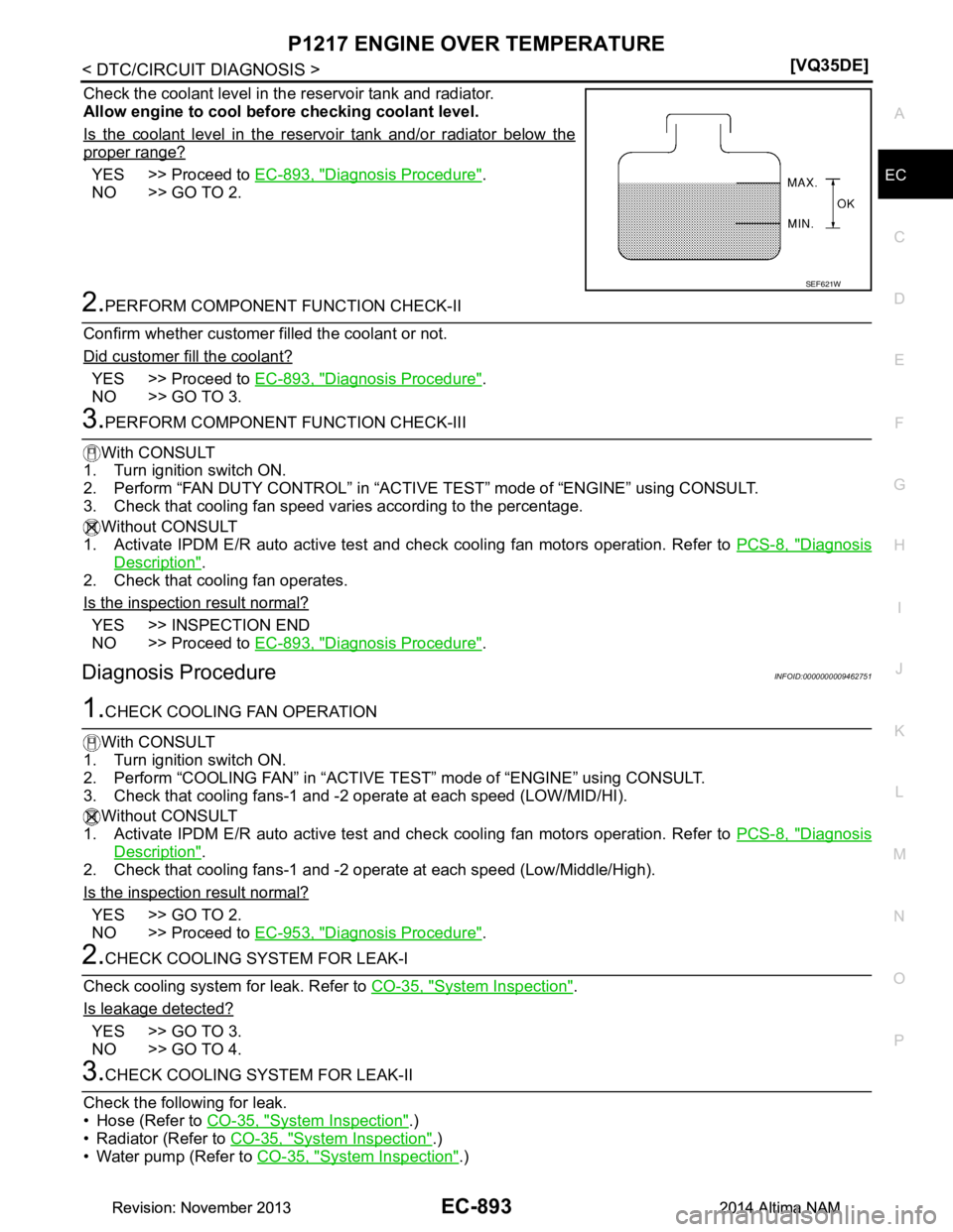
Check the coolant level in the reservoir tank and radiator.
Allow engine to cool befo re checking coolant level.
Is the coolant level in the reservoir tank and/or radiator below the
proper range?
YES >> Proceed to EC-893, "Diagnosis Procedure".
NO >> GO TO 2.
2.PERFORM COMPONENT FUNCTION CHECK-II
Confirm whether customer filled the coolant or not.
Did customer fill the coolant?
YES >> Proceed to EC-893, "Diagnosis Procedure".
NO >> GO TO 3.
3.PERFORM COMPONENT FUNCTION CHECK-III
With CONSULT
1. Turn ignition switch ON.
2. Perform “FAN DUTY CONTROL” in “ACTI VE TEST” mode of “ENGINE” using CONSULT.
3. Check that cooling fan speed varies according to the percentage.
Without CONSULT
1. Activate IPDM E/R auto active test and check cooling fan motors operation. Refer to PCS-8, "Diagnosis
Description".
2. Check that cooling fan operates.
Is the inspection result normal?
YES >> INSPECTION END
NO >> Proceed to EC-893, "Diagnosis Procedure"
.
Diagnosis ProcedureINFOID:0000000009462751
1.CHECK COOLING FAN OPERATION
With CONSULT
1. Turn ignition switch ON.
2. Perform “COOLING FAN” in “ACTIVE TE ST” mode of “ENGINE” using CONSULT.
3. Check that cooling fans-1 and -2 operate at each speed (LOW/MID/HI).
Without CONSULT
1. Activate IPDM E/R auto active test and check cooling fan motors operation. Refer to PCS-8, "Diagnosis
Description".
2. Check that cooling fans-1 and -2 operate at each speed (Low/Middle/High).
Is the inspection result normal?
YES >> GO TO 2.
NO >> Proceed to EC-953, "Diagnosis Procedure"
.
2.CHECK COOLING SYSTEM FOR LEAK-I
Check cooling system for leak. Refer to CO-35, "System Inspection"
.
Is leakage detected?
YES >> GO TO 3.
NO >> GO TO 4.
3.CHECK COOLING SYSTEM FOR LEAK-II
Check the following for leak.
• Hose (Refer to CO-35, "System Inspection"
.)
• Radiator (Refer to CO-35, "System Inspection"
.)
• Water pump (Refer to CO-35, "System Inspection"
.)
SEF621W
Revision: November 20132014 Altima NAMRevision: November 20132014 Altima NAM
Page 1990 of 4801
EC-990
< SYMPTOM DIAGNOSIS >[VQ35DE]
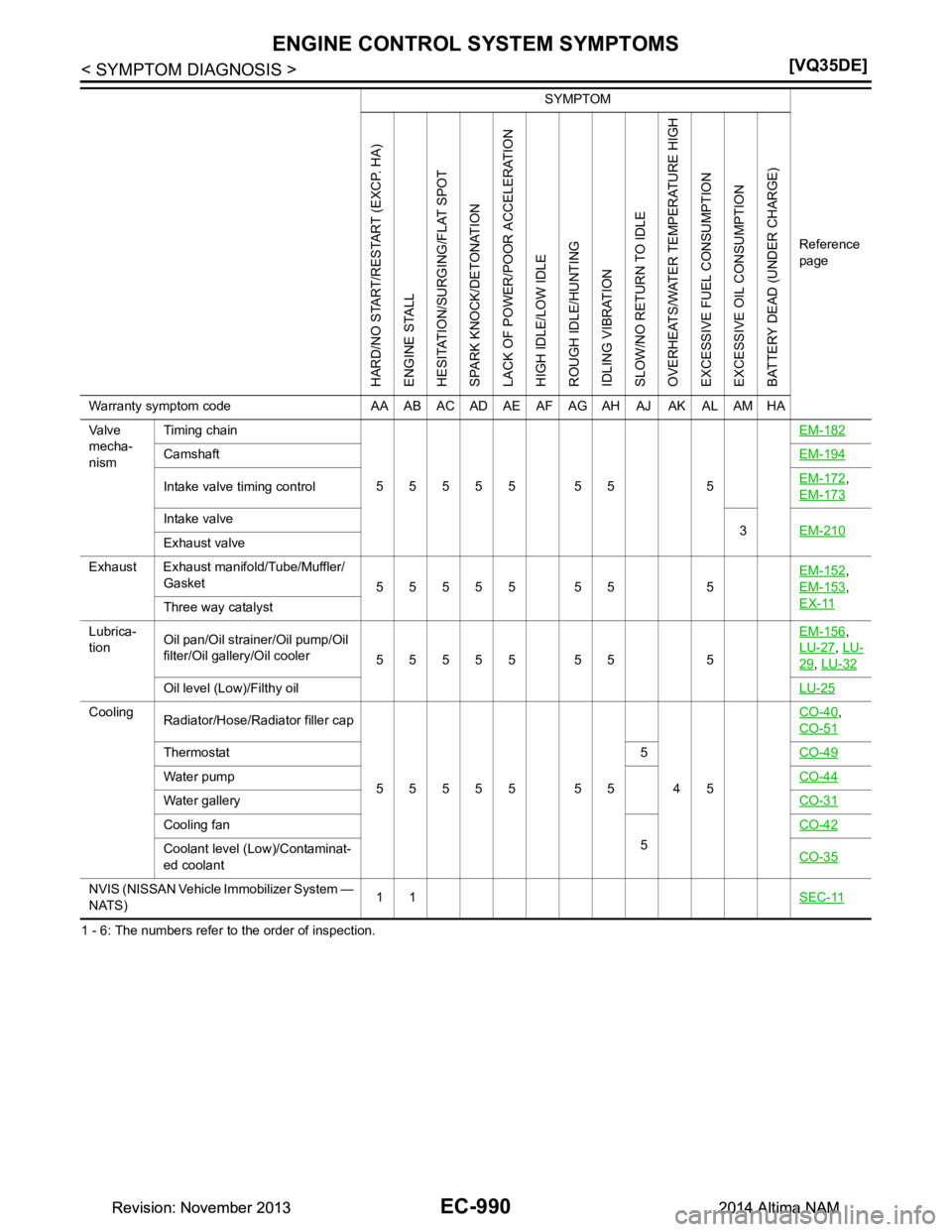
ENGINE CONTROL SYSTEM SYMPTOMS
1 - 6: The numbers refer to the order of inspection.Va l v e
mecha-
nism Timing chain
55555 55 5 EM-182
Camshaft
EM-194
Intake valve timing controlEM-172,
EM-173
Intake valve 3EM-210
Exhaust valve
Exhaust Exhaust manifold/Tube/Muffler/ Gasket 55555 55 5 EM-152
,
EM-153
,
EX-11
Three way catalyst
Lubrica-
tion Oil pan/Oil strainer/Oil pump/Oil
filter/Oil gallery/Oil cooler 55555 55 5 EM-156
,
LU-27
, LU-
29, LU-32
Oil level (Low)/Filthy oil LU-25
Cooling
Radiator/Hose/Radiator filler cap
55555 55 45 CO-40,
CO-51
Thermostat 5 CO-49
Water pumpCO-44
Water galleryCO-31
Cooling fan
5CO-42
Coolant level (Low)/Contaminat-
ed coolant CO-35
NVIS (NISSAN Vehicle Immobilizer System —
NATS) 11
SEC-11
SYMPTOM
Reference
page
HARD/NO START/RESTART (EXCP. HA)
ENGINE STALL
HESITATION/SURGING/FLAT SPOT
SPARK KNOCK/DETONATION
LACK OF POWER/POOR ACCELERATION
HIGH IDLE/LOW IDLE
ROUGH IDLE/HUNTING
IDLING VIBRATION
SLOW/NO RETURN TO IDLE
OVERHEATS/WATER TEMPERATURE HIGH
EXCESSIVE FUEL CONSUMPTION
EXCESSIVE OIL CONSUMPTION
BATTERY DEAD (UNDER CHARGE)
Warranty symptom code AA AB AC AD AE AF AG AH AJ AK AL AM HA
Revision: November 20132014 Altima NAMRevision: November 20132014 Altima NAM
Page 2083 of 4801
ENGINE ASSEMBLYEM-85
< UNIT REMOVAL AND INSTALLATION > [QR25DE]
C
D E
F
G H
I
J
K L
M A
EM
NP
O
27. Remove the LH and RH drive shafts. Refer to
FAX-10, "Removal and Installation (LH)", FAX-12, "Removal
and Installation (RH)".
28. Remove the drive belt. Refer to EM-19, "Removal and Installation"
.
29. Remove the front suspension member. Refer to FSU-20, "Removal and Installation"
.
30. Remove the A/C compressor with piping connected and support using suitable wire.
31. Disconnect the transaxle shift controls. Refer to TM-407, "Removal and Installation"
.
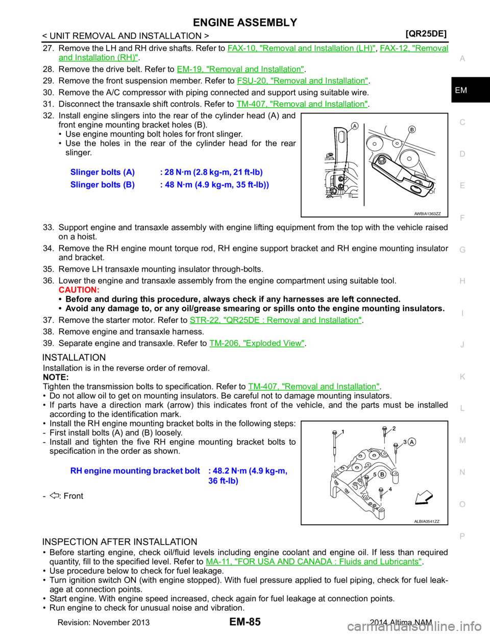
32. Install engine slingers into the rear of the cylinder head (A) and front engine mounting bracket holes (B).
• Use engine mounting bolt holes for front slinger.
• Use the holes in the rear of the cylinder head for the rear
slinger.
33. Support engine and transaxle assembly with engine lifti ng equipment from the top with the vehicle raised
on a hoist.
34. Remove the RH engine mount torque rod, RH engine support bracket and RH engine mounting insulator and bracket.
35. Remove LH transaxle mounting insulator through-bolts.
36. Lower the engine and transaxle assembly from the engine compartment using suitable tool.
CAUTION:
• Before and during this procedure, alw ays check if any harnesses are left connected.
• Avoid any damage to, or any oil/grease smearing or spills onto the engine mounting insulators.
37. Remove the starter motor. Refer to STR-22, "QR25DE : Removal and Installation"
.
38. Remove engine and transaxle harness.
39. Separate engine and transaxle. Refer to TM-206, "Exploded View"
.
INSTALLATION
Installation is in the reverse order of removal.
NOTE:
Tighten the transmission bolts to specification. Refer to TM-407, "Removal and Installation"
.
• Do not allow oil to get on mounting insulators. Be careful not to damage mounting insulators.
• If parts have a direction mark (arrow) this indicates front of the vehicle, and the parts must be installed
according to the identification mark.
• Install the RH engine mounting bracket bolts in the following steps:
- First install bolts (A) and (B) loosely.
- Install and tighten the five RH engine mounting bracket bolts to specification in the order as shown.
- : Front
INSPECTION AFTER INSTALLATION
• Before starting engine, check oil/fluid levels incl uding engine coolant and engine oil. If less than required
quantity, fill to the specified level. Refer to MA-11, "FOR USA AND CANADA : Fluids and Lubricants"
.
• Use procedure below to check for fuel leakage.
• Turn ignition switch ON (with engine stopped). With fuel pressure applied to fuel piping, check for fuel leak- age at connection points.
• Start engine. With engine speed increased, check again for fuel leakage at connection points.
• Run engine to check for unusual noise and vibration. Slinger bolts (A) : 28 N·m (2.8 kg-m, 21 ft-lb)
Slinger bolts (B) : 48 N·m (4.9 kg-m, 35 ft-lb))
AWBIA1363ZZ
RH engine mounting bracket bolt : 48.2 N·m (4.9 kg-m, 36 ft-lb)
ALBIA0541ZZ
Revision: November 20132014 Altima NAM
Page 2084 of 4801
EM-86
< UNIT REMOVAL AND INSTALLATION >[QR25DE]
ENGINE ASSEMBLY
NOTE:
If hydraulic pressure inside timing chain tensioner drops after removal and installation, slack in the guide
may generate a pounding noise during and just after engine start. However, this is normal. Noise will stop
after hydraulic pressure rises.
• Warm up engine thoroughly to make sure there is no leakage of fuel, exhaust gas, or any oils/fluids including engine oil and engine coolant.
• Bleed air from passages in lines and hoses, such as in cooling system.
• After cooling down engine, again check oil/fluid levels including engine oil and engine coolant. Refill to spec- ified level, if necessary.
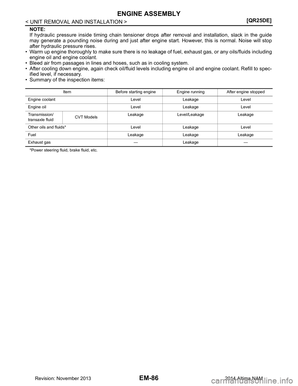
• Summary of the inspection items:
*Power steering fluid, brake fluid, etc. Item Before starting engine Engine running After engine stopped
Engine coolant Level Leakage Level
Engine oil Level Leakage Level
Transmission/
transaxle fluid CVT Models
Leakage Level/Leakage Leakage
Other oils and fluids* Level Leakage Level
Fuel Leakage Leakage Leakage
Exhaust gas — Leakage —
Revision: November 20132014 Altima NAM
Page 2086 of 4801
EM-88
< UNIT DISASSEMBLY AND ASSEMBLY >[QR25DE]
CYLINDER BLOCK
Disassembly and Assembly
INFOID:0000000009460510
CAUTION:
Apply new engine oil to parts marked in illustration before installation.
NOTE:
The following procedures explain how to disassem ble the engine with the engine stand fastened to the bell
housing. Some steps may be different if using a different type of engine stand.
DISASSEMBLY
1. Remove the engine and transaxle as an assembly from the vehicle, and separate the transaxle from the
engine. Refer to EM-84, "Removal and Installation"
.
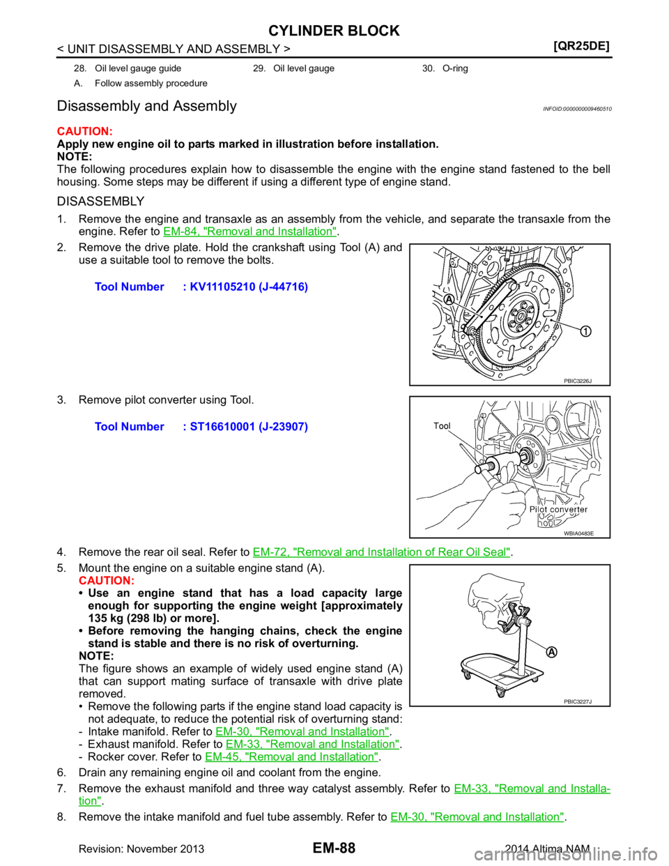
2. Remove the drive plate. Hold the crankshaft using Tool (A) and use a suitable tool to remove the bolts.
3. Remove pilot converter using Tool.
4. Remove the rear oil seal. Refer to EM-72, "Removal and Installation of Rear Oil Seal"
.
5. Mount the engine on a suitable engine stand (A). CAUTION:
• Use an engine stand that has a load capacity large
enough for supporting the engine weight [approximately
135 kg (298 lb) or more].
• Before removing the hanging chains, check the engine
stand is stable and there is no risk of overturning.
NOTE:
The figure shows an example of widely used engine stand (A)
that can support mating surface of transaxle with drive plate
removed.
• Remove the following parts if the engine stand load capacity is not adequate, to reduce the potential risk of overturning stand:
- Intake manifold. Refer to EM-30, "Removal and Installation"
.
- Exhaust manifold. Refer to EM-33, "Removal and Installation"
.
- Rocker cover. Refer to EM-45, "Removal and Installation"
.
6. Drain any remaining engine oil and coolant from the engine.
7. Remove the exhaust manifold and three way catalyst assembly. Refer to EM-33, "Removal and Installa-
tion".
8. Remove the intake manifold and fuel tube assembly. Refer to EM-30, "Removal and Installation"
.
28. Oil level gauge guide 29. Oil level gauge 30. O-ring
A. Follow assembly procedure
Tool Number : KV11105210 (J-44716)
PBIC3226J
Tool Number : ST16610001 (J-23907)
WBIA0483E
PBIC3227J
Revision: November 20132014 Altima NAM
Page 2156 of 4801
EM-158
< REMOVAL AND INSTALLATION >[VQ35DE]
OIL PAN AND OIL STRAINER
1. Remove the engine from the vehicle. Refer to
EM-220, "Removal and Installation".
2. Drain the engine oil. Refer to LU-26, "Changing Engine Oil"
.
3. Remove the oil level gauge guide.
4. Remove the drive belt. Refer to EM-134, "Removal and Installation"
.
5. Disconnect the A/C compressor harness connector.
6. Remove the A/C compressor bolts and remove the A/C compressor. Refer to HA-30, "COMPRESSOR :
Removal and Installation".
7. Remove coolant pipe bolts. Refer to CO-51, "Removal and Installation"
.
8. Disconnect the coolant lines from the engine oil cooler.
9. Remove the oil filter and engine oil cooler from the upper oil pan.
10. Remove the oil pressure switch, and the cranks haft position sensor (POS) from the upper oil pan.
11. Remove the lower oil pan. Refer to EM-156, "Removal and Installation (Lower Oil Pan)"
.
12. Remove the upper oil pan.
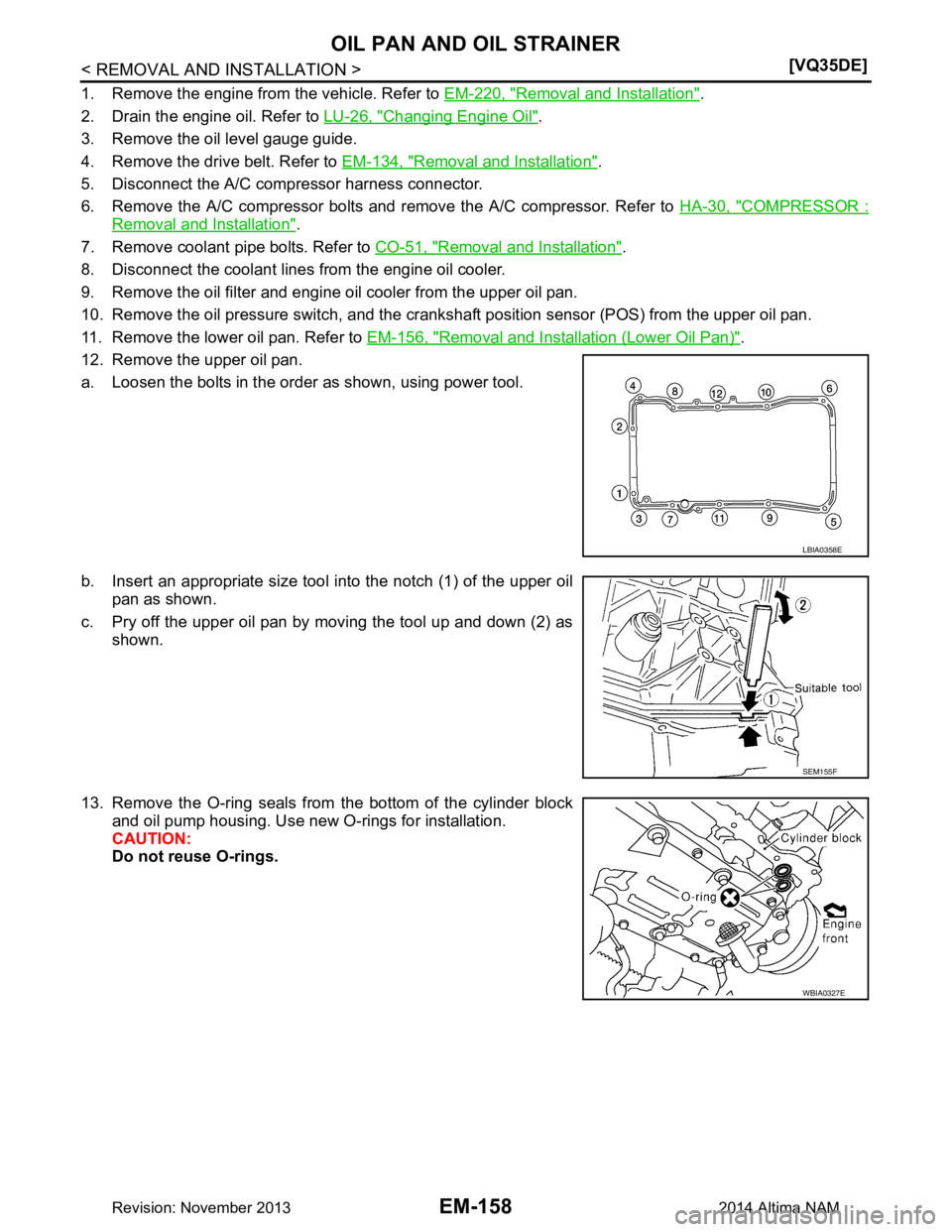
a. Loosen the bolts in the order as shown, using power tool.
b. Insert an appropriate size tool into the notch (1) of the upper oil pan as shown.
c. Pry off the upper oil pan by moving the tool up and down (2) as shown.
13. Remove the O-ring seals from the bottom of the cylinder block and oil pump housing. Use new O-rings for installation.
CAUTION:
Do not reuse O-rings.
LBIA0358E
SEM155F
WBIA0327E
Revision: November 20132014 Altima NAM
Page 2158 of 4801
EM-160
< REMOVAL AND INSTALLATION >[VQ35DE]
OIL PAN AND OIL STRAINER
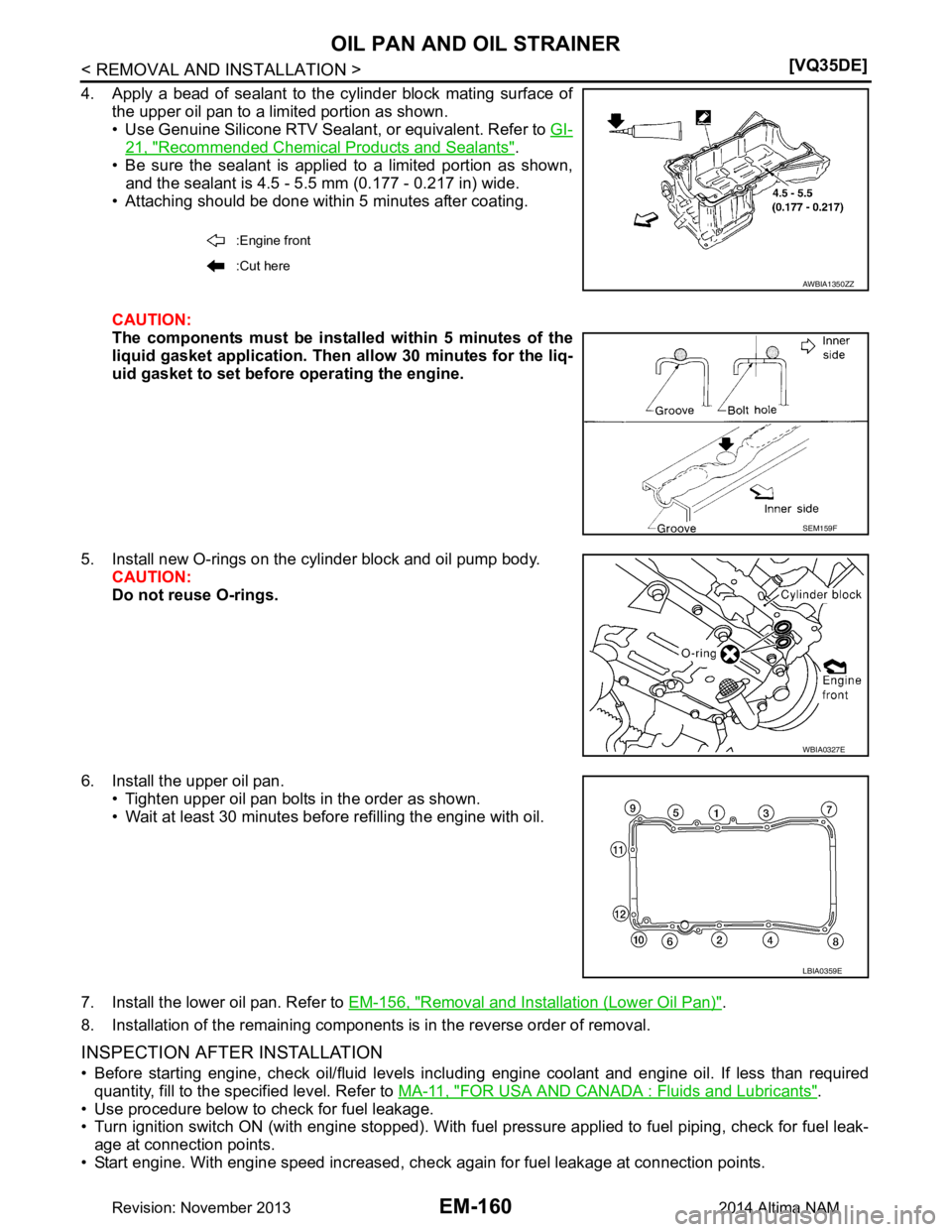
4. Apply a bead of sealant to the cylinder block mating surface of
the upper oil pan to a limited portion as shown.
• Use Genuine Silicone RTV Sealant, or equivalent. Refer to GI-
21, "Recommended Chemical Products and Sealants".
• Be sure the sealant is applied to a limited portion as shown, and the sealant is 4.5 - 5.5 mm (0.177 - 0.217 in) wide.
• Attaching should be done within 5 minutes after coating.
CAUTION:
The components must be instal led within 5 minutes of the
liquid gasket applicat ion. Then allow 30 minutes for the liq-
uid gasket to set before operating the engine.
5. Install new O-rings on the cylinder block and oil pump body. CAUTION:
Do not reuse O-rings.
6. Install the upper oil pan. • Tighten upper oil pan bolts in the order as shown.
• Wait at least 30 minutes before refilling the engine with oil.
7. Install the lower oil pan. Refer to EM-156, "Removal and Installation (Lower Oil Pan)"
.
8. Installation of the remaining components is in the reverse order of removal.
INSPECTION AFTER INSTALLATION
• Before starting engine, check oil/fluid levels incl uding engine coolant and engine oil. If less than required
quantity, fill to the specified level. Refer to MA-11, "FOR USA AND CANADA : Fluids and Lubricants"
.
• Use procedure below to check for fuel leakage.
• Turn ignition switch ON (with engine stopped). With fuel pressure applied to fuel piping, check for fuel leak- age at connection points.
• Start engine. With engine speed increased, che ck again for fuel leakage at connection points.
:Engine front
:Cut here
AWBIA1350ZZ
SEM159F
WBIA0327E
LBIA0359E
Revision: November 20132014 Altima NAM
Page 2159 of 4801
OIL PAN AND OIL STRAINEREM-161
< REMOVAL AND INSTALLATION > [VQ35DE]
C
D E
F
G H
I
J
K L
M A
EM
NP
O
• Run engine to check for unusual noise and vibration.
NOTE:
If hydraulic pressure inside timing chain tensioner dr ops after removal and installation, slack in the guide
may generate a pounding noise during and just after engine start. However, this is normal. Noise will stop
after hydraulic pressure rises.
• Warm up engine thoroughly to make sure there is no leak age of fuel, exhaust gas, or any oils/fluids including
engine oil and engine coolant.
• Bleed air from passages in lines and hoses, such as in cooling system.
• After cooling down engine, again check oil/fluid levels including engine oil and engine coolant. Refill to spec-
ified level, if necessary.
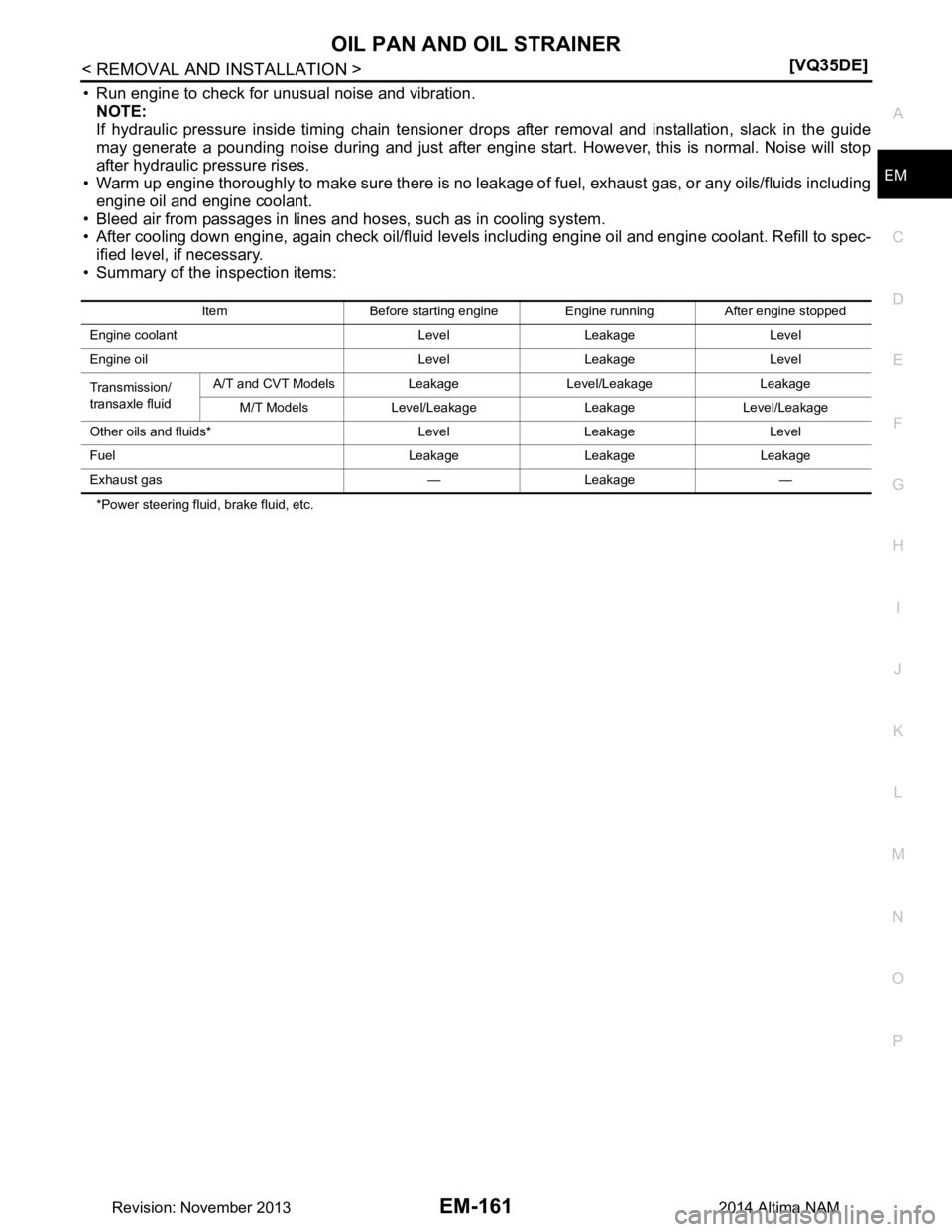
• Summary of the inspection items:
*Power steering fluid, brake fluid, etc. Item Before starting engine Engine running After engine stopped
Engine coolant Level Leakage Level
Engine oil Level Leakage Level
Transmission/
transaxle fluid A/T and CVT Models Leakage Level/Leakage Leakage
M/T Models Level/Leakage Leakage Level/Leakage
Other oils and fluids* Level Leakage Level
Fuel Leakage Leakage Leakage
Exhaust gas — Leakage —
Revision: November 20132014 Altima NAM
Page 2179 of 4801
FRONT TIMING CHAIN CASEEM-181
< REMOVAL AND INSTALLATION > [VQ35DE]
C
D E
F
G H
I
J
K L
M A
EM
NP
O
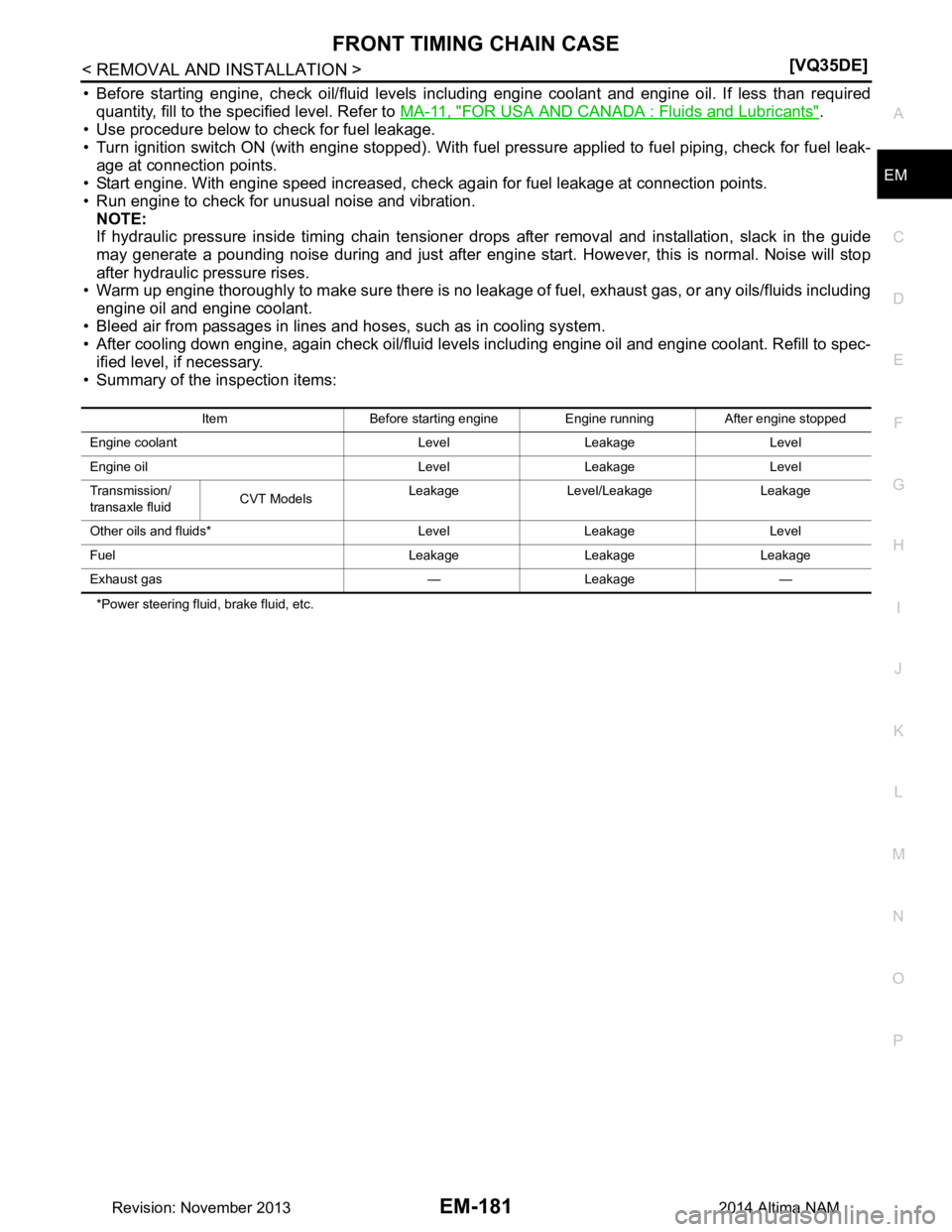
• Before starting engine, check oil/fluid levels incl
uding engine coolant and engine oil. If less than required
quantity, fill to the specified level. Refer to MA-11, "FOR USA AND CANADA : Fluids and Lubricants"
.
• Use procedure below to check for fuel leakage.
• Turn ignition switch ON (with engine stopped). With fuel pressure applied to fuel piping, check for fuel leak-
age at connection points.
• Start engine. With engine speed increased, check again for fuel leakage at connection points.
• Run engine to check for unusual noise and vibration. NOTE:
If hydraulic pressure inside timing chain tensioner dr ops after removal and installation, slack in the guide
may generate a pounding noise during and just after engine start. However, this is normal. Noise will stop
after hydraulic pressure rises.
• Warm up engine thoroughly to make sure there is no leak age of fuel, exhaust gas, or any oils/fluids including
engine oil and engine coolant.
• Bleed air from passages in lines and hoses, such as in cooling system.
• After cooling down engine, again check oil/fluid levels including engine oil and engine coolant. Refill to spec- ified level, if necessary.
• Summary of the inspection items:
*Power steering fluid, brake fluid, etc. Item Before starting engine Engine running After engine stopped
Engine coolant Level Leakage Level
Engine oil Level Leakage Level
Transmission/
transaxle fluid CVT Models Leakage Level/Leakage Leakage
Other oils and fluids* Level Leakage Level
Fuel Leakage Leakage Leakage
Exhaust gas — Leakage —
Revision: November 20132014 Altima NAM
Page 2220 of 4801
EM-222
< UNIT REMOVAL AND INSTALLATION >[VQ35DE]
ENGINE ASSEMBLY
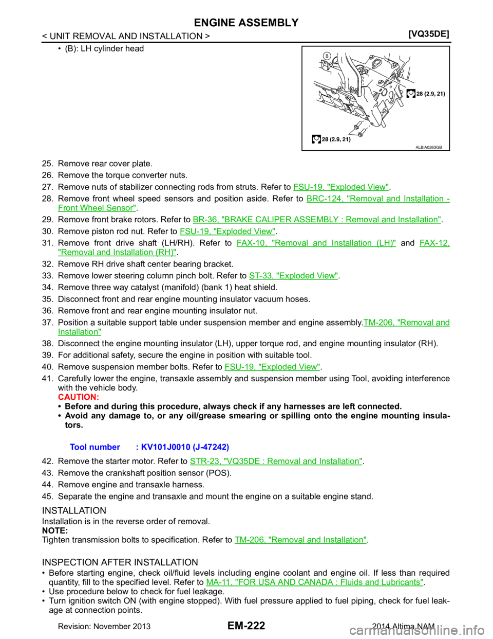
• (B): LH cylinder head
25. Remove rear cover plate.
26. Remove the torque converter nuts.
27. Remove nuts of stabilizer connecting rods from struts. Refer to FSU-19, "Exploded View"
.
28. Remove front wheel speed sensors and position aside. Refer to BRC-124, "Removal and Installation -
Front Wheel Sensor".
29. Remove front brake rotors. Refer to BR-36, "BRAKE CALIPER ASSEMBLY : Removal and Installation"
.
30. Remove piston rod nut. Refer to FSU-19, "Exploded View"
.
31. Remove front drive shaft (LH/RH). Refer to FAX-10, "Removal and Installation (LH)"
and FAX-12,
"Removal and Installation (RH)".
32. Remove RH drive shaft center bearing bracket.
33. Remove lower steering column pinch bolt. Refer to ST-33, "Exploded View"
.
34. Remove three way catalyst (manifold) (bank 1) heat shield.
35. Disconnect front and rear engine mounting insulator vacuum hoses.
36. Remove front and rear engine mounting insulator nut.
37. Position a suitable support table under suspension member and engine assembly. TM-206, "Removal and
Installation"
38. Disconnect the engine mounting insulator (LH), upper torque rod, and engine mounting insulator (RH).
39. For additional safety, secure the engine in position with suitable tool.
40. Remove suspension member bolts. Refer to FSU-19, "Exploded View"
.
41. Carefully lower the engine, transaxle assembly and suspension member using Tool, avoiding interference
with the vehicle body.
CAUTION:
• Before and during this procedure, alw ays check if any harnesses are left connected.
• Avoid any damage to, or any oil/grease smearin g or spilling onto the engine mounting insula-
tors.
42. Remove the starter motor. Refer to STR-23, "VQ35DE : Removal and Installation"
.
43. Remove the crankshaft position sensor (POS).
44. Remove engine and transaxle harness.
45. Separate the engine and transaxle and mount the engine on a suitable engine stand.
INSTALLATION
Installation is in the reverse order of removal.
NOTE:
Tighten transmission bolts to specification. Refer to TM-206, "Removal and Installation"
.
INSPECTION AFTER INSTALLATION
• Before starting engine, check oil/fluid levels including engine coolant and engine oil. If less than required
quantity, fill to the specified level. Refer to MA-11, "FOR USA AND CANADA : Fluids and Lubricants"
.
• Use procedure below to check for fuel leakage.
• Turn ignition switch ON (with engine stopped). With fuel pressure applied to fuel piping, check for fuel leak-
age at connection points.
ALBIA0263GB
Tool number : KV101J0010 (J-47242)
Revision: November 20132014 Altima NAM