NISSAN TEANA 2014 Service Manual
Manufacturer: NISSAN, Model Year: 2014, Model line: TEANA, Model: NISSAN TEANA 2014Pages: 4801, PDF Size: 51.2 MB
Page 4101 of 4801
SRC-108
< SYMPTOM DIAGNOSIS >
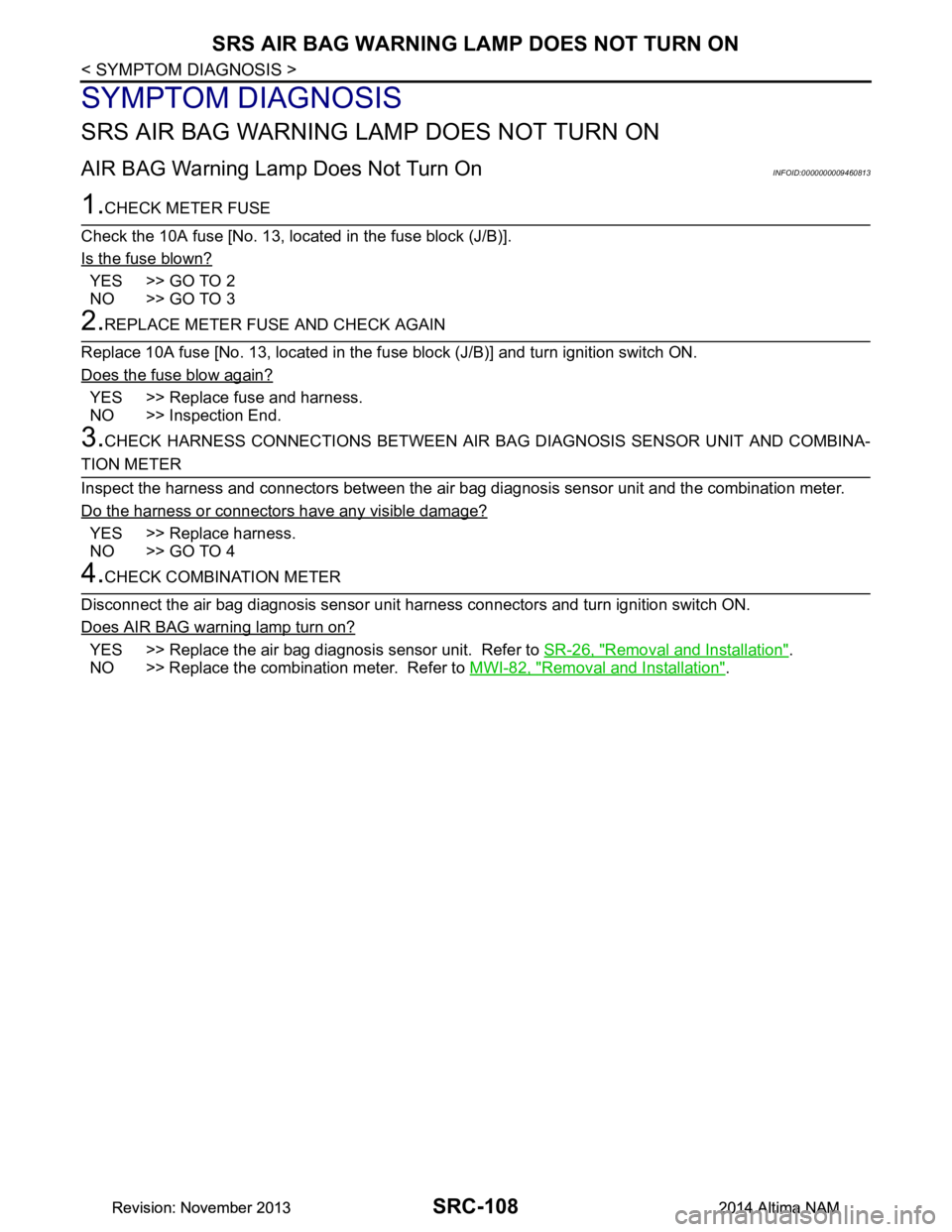
SRS AIR BAG WARNING LAMP DOES NOT TURN ON
SYMPTOM DIAGNOSIS
SRS AIR BAG WARNING LAMP DOES NOT TURN ON
AIR BAG Warning Lamp Does Not Turn OnINFOID:0000000009460813
1.CHECK METER FUSE
Check the 10A fuse [No. 13, loca ted in the fuse block (J/B)].
Is the fuse blown?
YES >> GO TO 2
NO >> GO TO 3
2.REPLACE METER FUSE AND CHECK AGAIN
Replace 10A fuse [No. 13, located in the fu se block (J/B)] and turn ignition switch ON.
Does the fuse blow again?
YES >> Replace fuse and harness.
NO >> Inspection End.
3.CHECK HARNESS CONNECTIONS BET WEEN AIR BAG DIAGNOSIS SENSOR UNIT AND COMBINA-
TION METER
Inspect the harness and connectors between the air bag diagnosis sensor unit and the combination meter.
Do the harness or connectors have any visible damage?
YES >> Replace harness.
NO >> GO TO 4
4.CHECK COMBINATION METER
Disconnect the air bag diagnosis sensor unit harness connectors and turn ignition switch ON.
Does AIR BAG warning lamp turn on?
YES >> Replace the air bag diagnosis sensor unit. Refer to SR-26, "Removal and Installation".
NO >> Replace the combination meter. Refer to MWI-82, "Removal and Installation"
.
Revision: November 20132014 Altima NAMRevision: November 20132014 Altima NAM
Page 4102 of 4801
SRS AIR BAG WARNING LAMP DOES NOT TURN OFF
SRC-109
< SYMPTOM DIAGNOSIS >
C
D E
F
G
I
J
K L
M A
B
SRC
N
O P
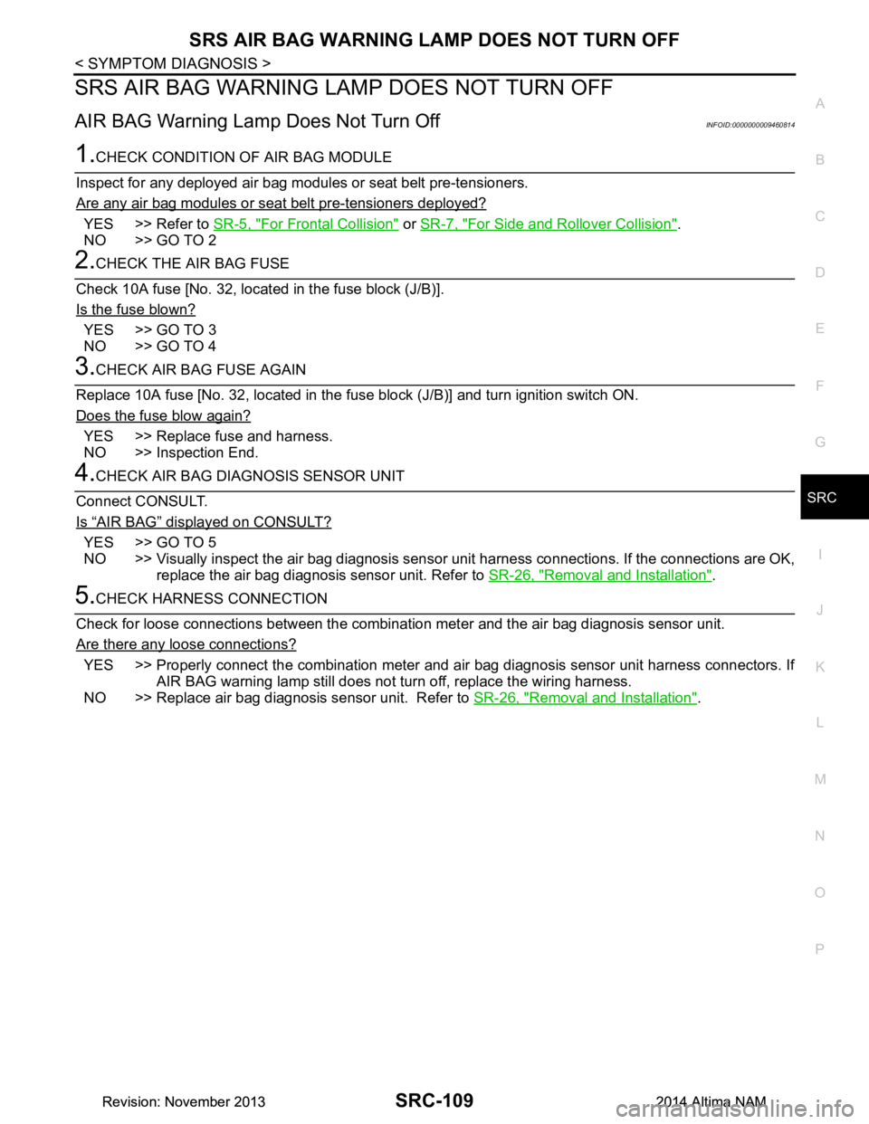
SRS AIR BAG WARNING LAMP DOES NOT TURN OFF
AIR BAG Warning Lamp Does Not Turn OffINFOID:0000000009460814
1.CHECK CONDITION OF AIR BAG MODULE
Inspect for any deployed air bag modules or seat belt pre-tensioners.
Are any air bag modules or seat belt pre-tensioners deployed?
YES >> Refer to SR-5, "For Frontal Collision" or SR-7, "For Side and Rollover Collision".
NO >> GO TO 2
2.CHECK THE AIR BAG FUSE
Check 10A fuse [No. 32, locat ed in the fuse block (J/B)].
Is the fuse blown?
YES >> GO TO 3
NO >> GO TO 4
3.CHECK AIR BAG FUSE AGAIN
Replace 10A fuse [No. 32, located in the fu se block (J/B)] and turn ignition switch ON.
Does the fuse blow again?
YES >> Replace fuse and harness.
NO >> Inspection End.
4.CHECK AIR BAG DIAGNOSIS SENSOR UNIT
Connect CONSULT.
Is
“AIR BAG” displayed on CONSULT?
YES >> GO TO 5
NO >> Visually inspect the air bag diagnosis sensor unit harness connections. If the connections are OK,
replace the air bag diagnosis sensor unit. Refer to SR-26, "Removal and Installation"
.
5.CHECK HARNESS CONNECTION
Check for loose connections between the combination meter and the air bag diagnosis sensor unit.
Are there any loose connections?
YES >> Properly connect the combination meter and air bag diagnosis sensor unit harness connectors. If AIR BAG warning lamp still does not tu rn off, replace the wiring harness.
NO >> Replace air bag diagnosis sensor unit. Refer to SR-26, "Removal and Installation"
.
Revision: November 20132014 Altima NAMRevision: November 20132014 Altima NAM
Page 4103 of 4801
SRC-110
< SYMPTOM DIAGNOSIS >
SEAT BELT WARNING SYSTEM
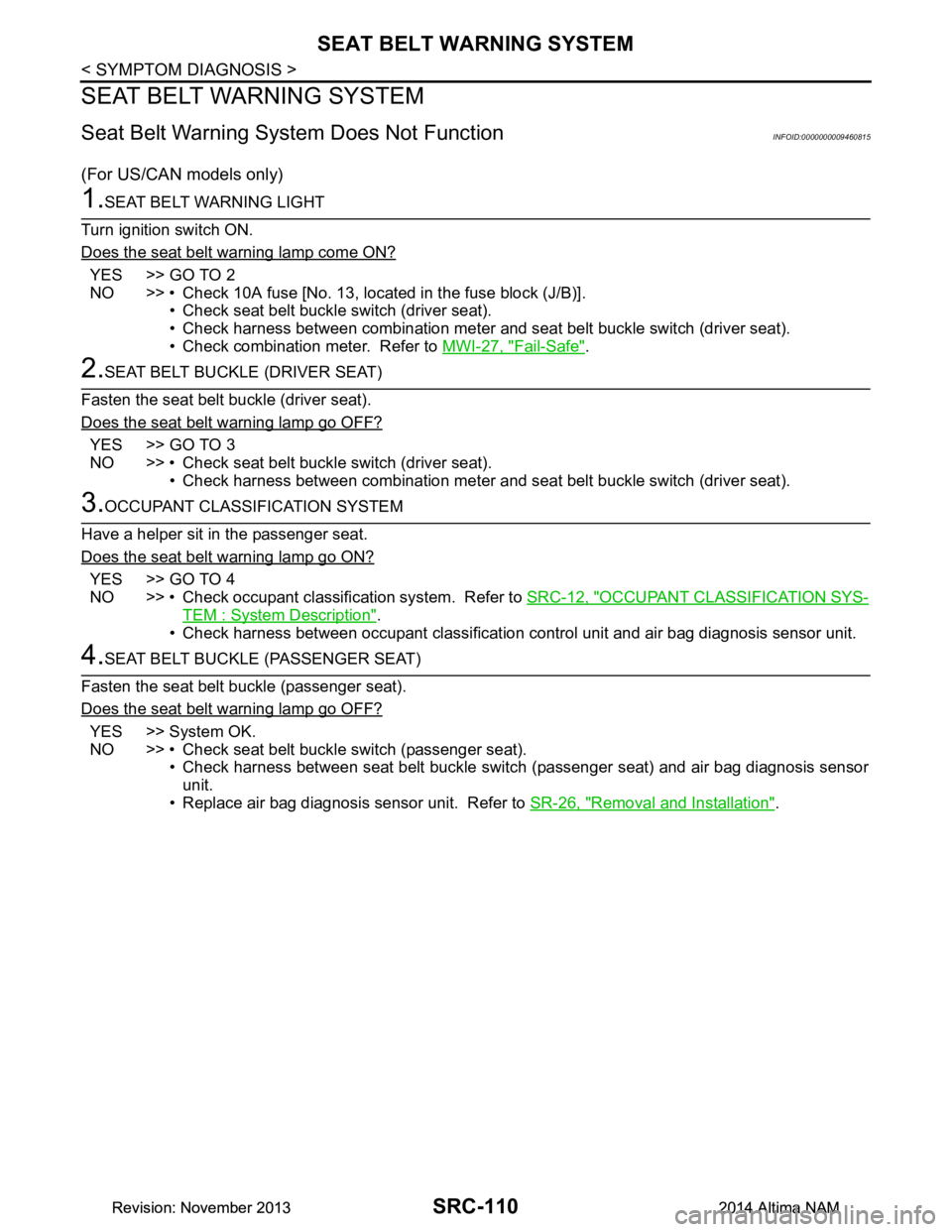
SEAT BELT WARNING SYSTEM
Seat Belt Warning System Does Not FunctionINFOID:0000000009460815
(For US/CAN models only)
1.SEAT BELT WARNING LIGHT
Turn ignition switch ON.
Does the seat belt warning lamp come ON?
YES >> GO TO 2
NO >> • Check 10A fuse [No. 13, located in the fuse block (J/B)].
• Check seat belt buckle switch (driver seat).
• Check harness between combination meter and seat belt buckle switch (driver seat).
• Check combination meter. Refer to MWI-27, "Fail-Safe"
.
2.SEAT BELT BUCKLE (DRIVER SEAT)
Fasten the seat belt buckle (driver seat).
Does the seat belt warning lamp go OFF?
YES >> GO TO 3
NO >> • Check seat belt buckle switch (driver seat). • Check harness between combination meter and seat belt buckle switch (driver seat).
3.OCCUPANT CLASSIFICATION SYSTEM
Have a helper sit in the passenger seat.
Does the seat belt warning lamp go ON?
YES >> GO TO 4
NO >> • Check occupant classification system. Refer to SRC-12, "OCCUPANT CLASSIFICATION SYS-
TEM : System Description".
• Check harness between occupant classification control unit and air bag diagnosis sensor unit.
4.SEAT BELT BUCKLE (PASSENGER SEAT)
Fasten the seat belt buckle (passenger seat).
Does the seat belt warning lamp go OFF?
YES >> System OK.
NO >> • Check seat belt buckle switch (passenger seat). • Check harness between seat belt buckle switch (passenger seat) and air bag diagnosis sensorunit.
• Replace air bag diagnosis sensor unit. Refer to SR-26, "Removal and Installation"
.
Revision: November 20132014 Altima NAMRevision: November 20132014 Altima NAM
Page 4104 of 4801

ST-1
STEERING
C
D E
F
H I
J
K L
M
SECTION ST
A
B
ST
N
O P
CONTENTS
STEERING SYSTEM
PRECAUTION ................ ...............................3
PRECAUTIONS .............................................. .....3
Precaution for Supplemental Restraint System
(SRS) "AIR BAG" and "SEAT BELT PRE-TEN-
SIONER" ............................................................. ......
3
Precaution for Steering System .......................... ......3
Precaution for Work ............................................ ......3
PREPARATION ............................................5
PREPARATION .............................................. .....5
Special Service Tool ........................................... ......5
Commercial Service Tool ..........................................5
SYSTEM DESCRIPTION ..............................7
COMPONENT PARTS ................................... .....7
HEATED STEERING WHEEL SYSTEM ............... ......7
HEATED STEERING WHEEL SYSTEM : Compo-
nent Parts Location ............................................. ......
7
HEATED STEERING WHEEL SYSTEM : Compo-
nent Description .................................................. ......
7
SYSTEM ..............................................................8
HEATED STEERING WHEEL SYSTEM ............... ......8
HEATED STEERING WHEEL SYSTEM : System
Diagram ............................................................... ......
8
HEATED STEERING WHEEL SYSTEM : System
Description .......................................................... ......
8
ECU DIAGNOSIS INFORMATION ...............9
A/C AUTO AMP. ............................................. .....9
List of ECU Reference ........................................ ......9
WIRING DIAGRAM ......................................10
HEATED STEERING WHEEL ........................ ....10
Wiring Diagram ................................................... ....10
BASIC INSPECTION ...................................13
DIAGNOSIS AND REPAIR WORK FLOW .......13
Work Flow ............................................................ ....13
POWER STEERING FLUID ..............................15
Inspection ................................................................15
STEERING WHEEL ..........................................16
Inspection ................................................................16
STEERING COLUMN ........................................18
Inspection ................................................................18
POWER STEERING OIL PUMP .......................19
Inspection ................................................................19
STEERING GEAR AND LINKAGE ...................20
Inspection ................................................................20
DTC/CIRCUIT DIAGNOSIS .........................21
POWER SUPPLY AND GROUND CIRCUIT ....21
A/C AUTO AMP. .................................................... ....21
A/C AUTO AMP. : Diagnosis Procedure .................21
HEATED STEERING WHEEL SYSTEM ...........22
Component Function Check ....................................22
Diagnosis Procedure ...............................................22
Component Inspection (Heated Steering Wheel
Switch) ................................................................. ....
24
Component Inspection (Heated Steering Relay) .....24
Component Inspection (Heated Steering Wheel) ....25
HEATED STEERING WHEEL SWITCH INDI-
CATOR LAMP ...................................................
26
Component Function Check ................................ ....26
Diagnosis Procedure ...............................................26
SYMPTOM DIAGNOSIS ..............................28
STEERING COLUMN ........................................28
Revision: November 20132014 Altima NAMRevision: November 20132014 Altima NAM
Page 4105 of 4801

ST-2
Symptom Table ......................................................28
NOISE, VIBRATION AND HARSHNESS
(NVH) TROUBLESHOOTING ......................... ...
29
NVH Troubleshooting Chart ................................ ...29
PERIODIC MAINTENANCE ..................... ...30
POWER STEERING FLUID ............................ ...30
Draining and Refilling .......................................... ...30
Air Bleeding Hydraulic System ...............................30
REMOVAL AND INSTAL LATION ...............31
STEERING WHEEL ........................................ ...31
Exploded View ..................................................... ...31
Removal and Installation ........................................31
STEERING COLUMN ........................................33
Exploded View ..................................................... ...33
Removal and Installation ........................................33
STEERING GEAR AND LINKAGE ....................36
Exploded View ..................................................... ...36
Removal and Installation ........................................36
POWER STEERING OIL PUMP ........................38
Exploded View ..................................................... ...38
Removal and Installation .........................................38
HYDRAULIC LINE .......................................... ...40
Exploded View ..................................................... ...40
Removal and Installation .........................................41
UNIT DISASSEMBLY AND ASSEMBLY ...43
STEERING GEAR AND LINKAGE ................ ...43
Exploded View ..................................................... ...43
Disassembly and Assembly ....................................43
POWER STEERING OIL PUMP ........................45
Disassembly and Assembly ................................. ...45
SERVICE DATA AND SPECIFICATIONS
(SDS) ............... ...........................................
46
SERVICE DATA AND SPECIFICATIONS
(SDS) .............................................................. ...
46
Steering Wheel .................................................... ...46
Steering Angle ........................................................46
Steering Column .....................................................46
Power Steering Gear ..............................................47
Power Steering Oil Pump ........................................48
Power Steering Fluid ...............................................48
Revision: November 20132014 Altima NAMRevision: November 20132014 Altima NAM
Page 4106 of 4801

PRECAUTIONSST-3
< PRECAUTION >
C
D E
F
H I
J
K L
M A
B
ST
N
O P
PRECAUTION
PRECAUTIONS
Precaution for Supplemental Restraint System (SRS) "AIR BAG" and "SEAT BELT
PRE-TENSIONER"
INFOID:0000000009951723
The Supplemental Restraint System such as “A IR BAG” and “SEAT BELT PRE-TENSIONER”, used along
with a front seat belt, helps to reduce the risk or severi ty of injury to the driver and front passenger for certain
types of collision. Information necessary to service t he system safely is included in the SR and SB section of
this Service Manual.
WARNING:
• To avoid rendering the SRS inoper ative, which could increase the risk of personal injury or death in
the event of a collision which would result in air bag inflation, all maintenance must be performed by
an authorized NISSAN/INFINITI dealer.
• Improper maintenance, including in correct removal and installation of the SRS, can lead to personal
injury caused by unintentional act ivation of the system. For removal of Spiral Cable and Air Bag
Module, see the SR section.
• Do not use electrical test equipm ent on any circuit related to the SRS unless instructed to in this
Service Manual. SRS wiring harnesses can be identi fied by yellow and/or orange harnesses or har-
ness connectors.
PRECAUTIONS WHEN USING POWER TOOLS (AIR OR ELECTRIC) AND HAMMERS
WARNING:
• When working near the Airbag Diagnosis Sensor Un it or other Airbag System sensors with the Igni-
tion ON or engine running, DO NOT use air or el ectric power tools or strike near the sensor(s) with a
hammer. Heavy vibration could activate the sensor( s) and deploy the air bag(s), possibly causing
serious injury.
• When using air or electric power tools or hammers , always switch the Ignition OFF, disconnect the
battery and wait at least three mi nutes before performing any service.
Precaution for Steering SystemINFOID:0000000009461240
• Before disassembly, thoroughly clean the outside of the unit.
• Disassembly should be done in a clean work area. It is im portant to prevent the internal parts from becoming
contaminated by dirt or other foreign matter.
• For easier and proper assembly, place disassembled parts in order on a parts rack.
• Use nylon cloth or paper towels to clean the parts; common shop rags can leave lint that might interfere with
their operation.
• Before inspection or reassembly, carefully clean al l parts with a general purpose, non-flammable solvent.
• Before assembly, apply a coat of recommended Genuine NISSAN PSF or equivalent to hydraulic parts.
Petroleum jelly may be applied to O-rings and seals. Do not use any grease.
• Replace all gaskets, seals and O-rings. Avoid damaging O-rings, seals and gaskets during installation. Per- form functional tests whenever designated.
Precaution for WorkINFOID:0000000009461241
• When removing or disassembling each component, be ca reful not to damage or deform it. If a component
may be subject to interference, be sure to protect it with a shop cloth.
• When removing (disengaging) components with a screwdriver or similar tool, be sure to wrap the component
with a shop cloth or vinyl tape to protect it.
• Protect the removed parts with a shop cloth and prevent them from being dropped.
• Replace a deformed or damaged clip.
• If a part is specified as a non-reusabl e part, always replace it with a new one.
• Be sure to tighten bolts and nuts securely to the specified torque.
• After installation is complete, be sure to check that each part works properly.
• Follow the steps below to clean components:
- Water soluble dirt:
• Dip a soft cloth into lukewarm water, wring the water out of the cloth and wipe the dirty area.
• Then rub with a soft, dry cloth.
-Oily dirt:
Revision: November 20132014 Altima NAMRevision: November 20132014 Altima NAM
Page 4107 of 4801

ST-4
< PRECAUTION >
PRECAUTIONS
• Dip a soft cloth into lukewarm water with mild detergent (concentration: within 2 to 3%) and wipe the dirtyarea.
• Then dip a cloth into fresh water, wring the water out of the cloth and wipe the detergent off.
• Then rub with a soft, dry cloth.
- Do not use organic solvent such as thinner, benzene, alcohol or gasoline.
- For genuine leather seats, use a genuine leather seat cleaner.
Revision: November 20132014 Altima NAMRevision: November 20132014 Altima NAM
Page 4108 of 4801
PREPARATIONST-5
< PREPARATION >
C
D E
F
H I
J
K L
M A
B
ST
N
O P
PREPARATION
PREPARATION
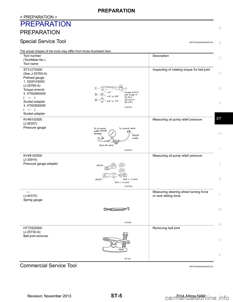
Special Service ToolINFOID:0000000009461242
The actual shapes of the tools may differ from those illustrated here.
Commercial Service ToolINFOID:0000000009461243
Tool number
(TechMate No.)
Tool name Description
ST3127S000
(See J-25765-A)
Preload gauge
1. GG9103000
(J-25765-A)
Torque wrench
2. HT62940000
(—)
Socket adapter
3. HT62900000
(—)
Socket adapter Inspecting of rotating torque for ball joint
KV48103500
(J-26357)
Pressure gauge Measuring oil pump relief pressure
KV48102500
(J-33914)
Pressure gauge adapter Measuring oil pump relief pressure
—
(J-44372)
Spring gauge Measuring steering wheel turning force
or rack sliding force
HT72520000
(J-25730-A)
Ball joint remover Removing ball joint
S-NT541
S-NT547
S-NT542
LST024
NT146
Revision: November 20132014 Altima NAMRevision: November 20132014 Altima NAM
Page 4109 of 4801
ST-6
< PREPARATION >
PREPARATION
Tool nameDescription
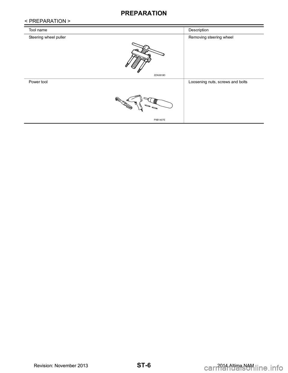
Steering wheel puller Removing steering wheel
Power tool Loosening nuts, screws and bolts
ZZA0819D
PIIB1407E
Revision: November 20132014 Altima NAMRevision: November 20132014 Altima NAM
Page 4110 of 4801
COMPONENT PARTSST-7
< SYSTEM DESCRIPTION >
C
D E
F
H I
J
K L
M A
B
ST
N
O P
SYSTEM DESCRIPTION
COMPONENT PARTS
HEATED STEERING WHEEL SYSTEM
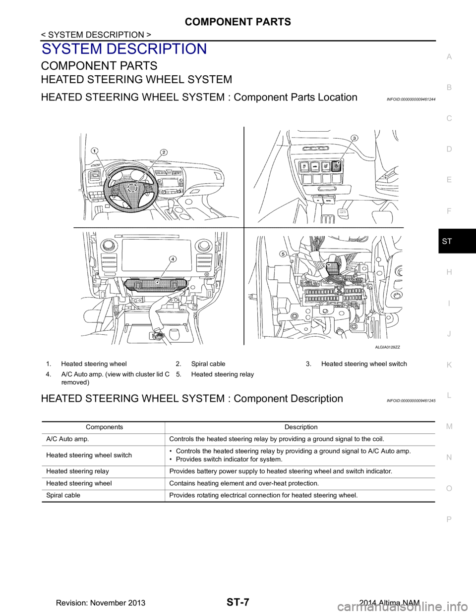
HEATED STEERING WHEEL SYSTEM : Component Parts LocationINFOID:0000000009461244
HEATED STEERING WHEEL SYSTEM : Component DescriptionINFOID:0000000009461245
1. Heated steering wheel 2. Spiral cable 3. Heated steering wheel switch
4. A/C Auto amp. (view with cluster lid C removed) 5. Heated steering relay
ALGIA0129ZZ
Components Description
A/C Auto amp. Controls the heated steering relay by providing a ground signal to the coil.
Heated steering wheel switch • Controls the heated steering relay by providing a ground signal to A/C Auto amp.
• Provides switch indicator for system.
Heated steering relay Provides battery power supply to heated steering wheel and switch indicator.
Heated steering wheel Contains heating element and over-heat protection.
Spiral cable Provides rotating electrical connection for heated steering wheel.
Revision: November 20132014 Altima NAMRevision: November 20132014 Altima NAM