NISSAN TEANA 2014 Service Manual
TEANA 2014
NISSAN
NISSAN
https://www.carmanualsonline.info/img/5/57390/w960_57390-0.png
NISSAN TEANA 2014 Service Manual
Trending: door lock, wiper blades, wheel torque, spark plugs replace, sunroof, fuel filter, park assist
Page 4141 of 4801
ST-38
< REMOVAL AND INSTALLATION >
POWER STEERING OIL PUMP
POWER STEERING OIL PUMP
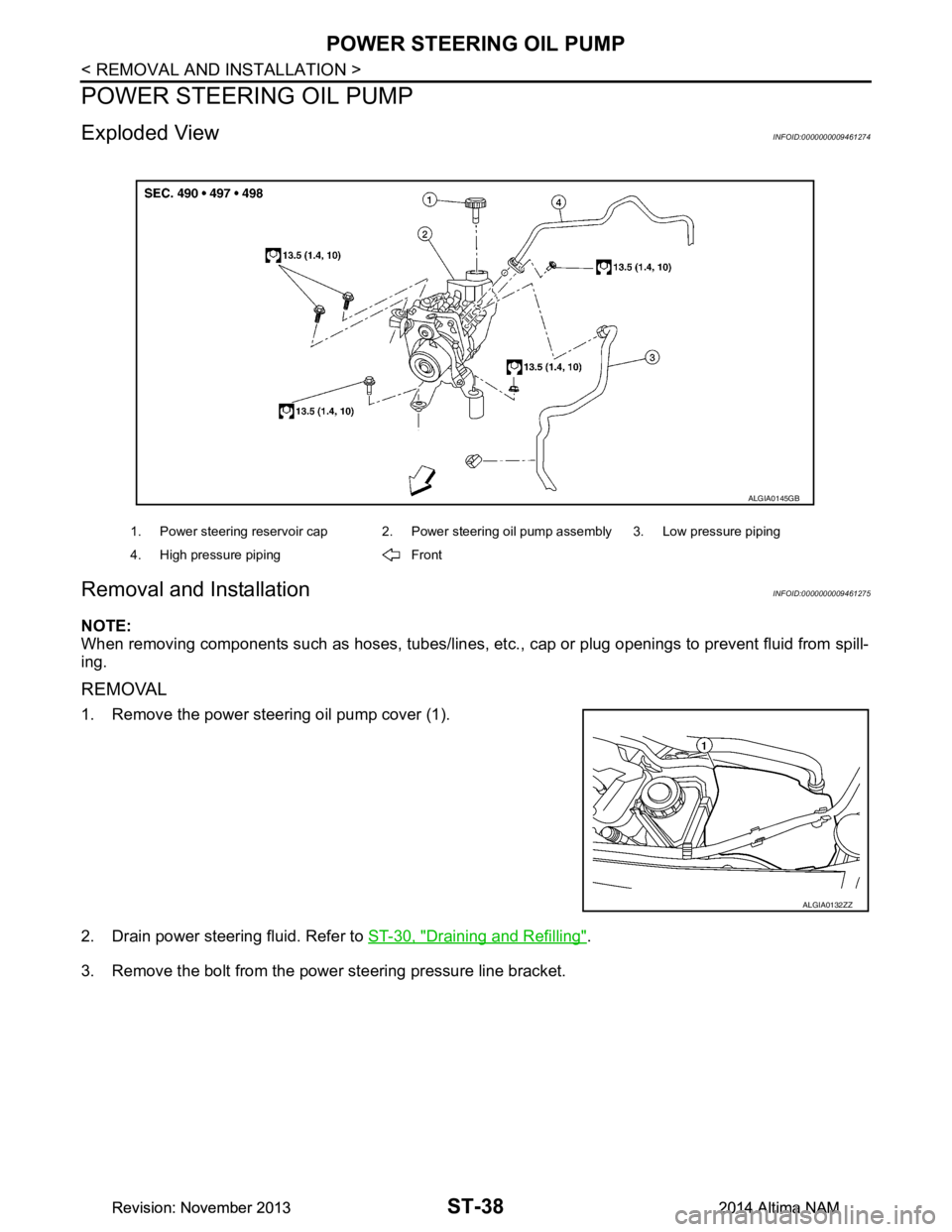
Exploded ViewINFOID:0000000009461274
Removal and InstallationINFOID:0000000009461275
NOTE:
When removing components such as hoses, tubes/lines, etc. , cap or plug openings to prevent fluid from spill-
ing.
REMOVAL
1. Remove the power steering oil pump cover (1).
2. Drain power steering fluid. Refer to ST-30, "Draining and Refilling"
.
3. Remove the bolt from the power steering pressure line bracket.
1. Power steering reservoir cap 2. Power steering oil pump assembly 3. Low pressure piping
4. High pressure piping Front
ALGIA0145GB
ALGIA0132ZZ
Revision: November 20132014 Altima NAMRevision: November 20132014 Altima NAM
Page 4142 of 4801
POWER STEERING OIL PUMPST-39
< REMOVAL AND INSTALLATION >
C
D E
F
H I
J
K L
M A
B
ST
N
O P
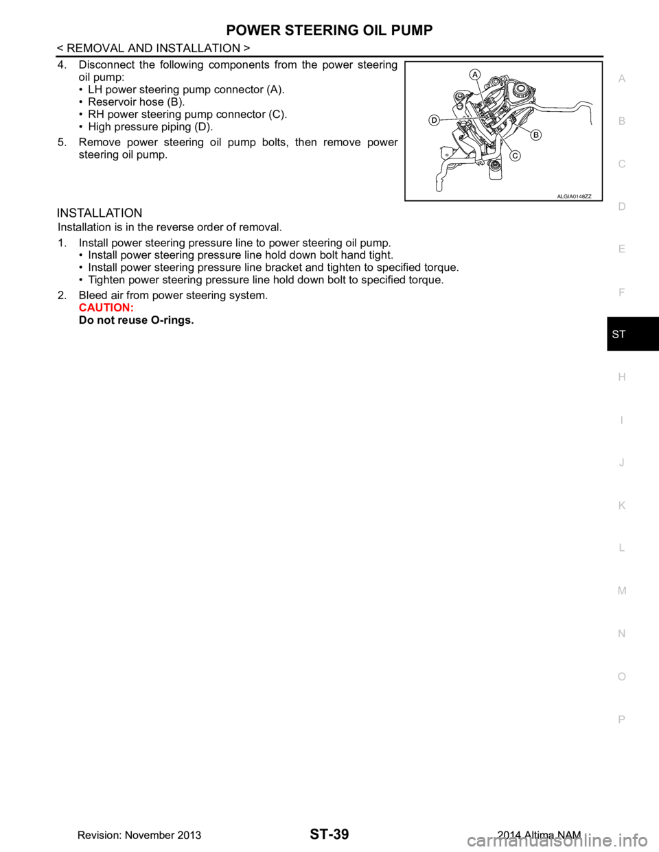
4. Disconnect the following components from the power steering oil pump:
• LH power steering pump connector (A).
• Reservoir hose (B).
• RH power steering pump connector (C).
• High pressure piping (D).
5. Remove power steering oil pump bolts, then remove power steering oil pump.
INSTALLATION
Installation is in the reverse order of removal.
1. Install power steering pressure line to power steering oil pump. • Install power steering pressure line hold down bolt hand tight.
• Install power steering pressure line bracket and tighten to specified torque.
• Tighten power steering pressure line hold down bolt to specified torque.
2. Bleed air from power steering system. CAUTION:
Do not reuse O-rings.
ALGIA0148ZZ
Revision: November 20132014 Altima NAMRevision: November 20132014 Altima NAM
Page 4143 of 4801
ST-40
< REMOVAL AND INSTALLATION >
HYDRAULIC LINE
HYDRAULIC LINE
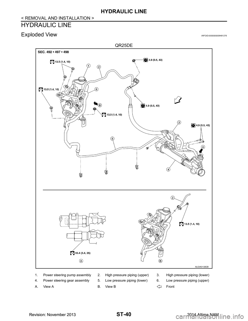
Exploded ViewINFOID:0000000009461276
QR25DE
ALGIA0133GB
1. Power steering pump assembly 2. High pressure piping (upper) 3. High pressure piping (lower)
4. Power steering gear assembly 5. Low pressure piping (lower) 6. Low pressure piping (upper)
A. View A B. View B Front
Revision: November 20132014 Altima NAMRevision: November 20132014 Altima NAM
Page 4144 of 4801
HYDRAULIC LINEST-41
< REMOVAL AND INSTALLATION >
C
D E
F
H I
J
K L
M A
B
ST
N
O P
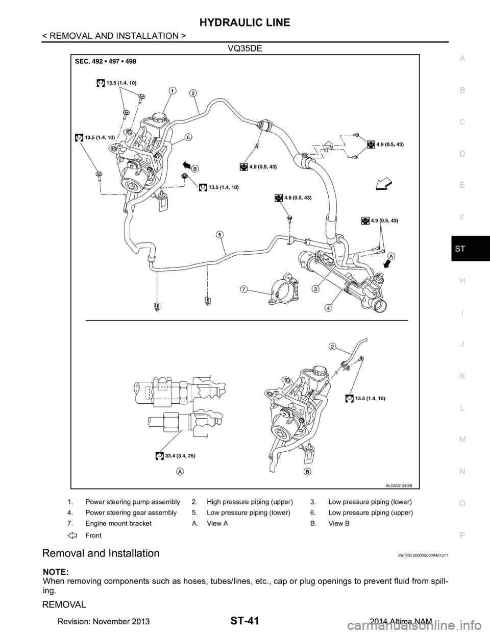
VQ35DE
Removal and InstallationINFOID:0000000009461277
NOTE:
When removing components such as hoses, tubes/lines, etc. , cap or plug openings to prevent fluid from spill-
ing.
REMOVAL
ALGIA0134GB
1. Power steering pump assembly 2. High pressure piping (upper) 3. Low pressure piping (lower)
4. Power steering gear assembly 5. Low pressure piping (lower) 6. Low pressure piping (upper)
7. Engine mount bracket A. View A B. View B
Front
Revision: November 20132014 Altima NAMRevision: November 20132014 Altima NAM
Page 4145 of 4801
ST-42
< REMOVAL AND INSTALLATION >
HYDRAULIC LINE
Refer to the component parts location illustration for hydraulic line removal. Refer to ST-40, "Exploded View".
CAUTION:
Do not reuse O-rings.
INSTALLATION
Installation is in the reverse order of removal.
• Bleed air from power steering system. Refer to ST-30, "Air Bleeding Hydraulic System"
.
• Check for fluid leaks. Repair as necessary.
CAUTION:
Do not reuse O-rings.
Revision: November 20132014 Altima NAMRevision: November 20132014 Altima NAM
Page 4146 of 4801
STEERING GEAR AND LINKAGEST-43
< UNIT DISASSEMBLY AND ASSEMBLY >
C
D E
F
H I
J
K L
M A
B
ST
N
O P
UNIT DISASSEMBLY AND ASSEMBLY
STEERING GEAR AND LINKAGE
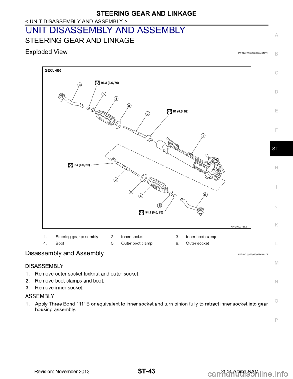
Exploded ViewINFOID:0000000009461278
Disassembly and AssemblyINFOID:0000000009461279
DISASSEMBLY
1. Remove outer socket locknut and outer socket.
2. Remove boot clamps and boot.
3. Remove inner socket.
ASSEMBLY
1. Apply Three Bond 1111B or equivalent to inner socket and turn pinion fully to retract inner socket into gear housing assembly.
1. Steering gear assembly 2. Inner socket 3. Inner boot clamp
4. Boot 5. Outer boot clamp 6. Outer socket
AWGIA0218ZZ
Revision: November 20132014 Altima NAMRevision: November 20132014 Altima NAM
Page 4147 of 4801
ST-44
< UNIT DISASSEMBLY AND ASSEMBLY >
STEERING GEAR AND LINKAGE
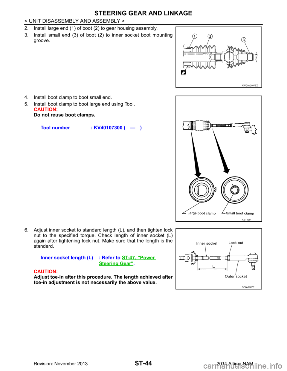
2. Install large end (1) of boot (2) to gear housing assembly.
3. Install small end (3) of boot (2) to inner socket boot mounting groove.
4. Install boot clamp to boot small end.
5. Install boot clamp to boot large end using Tool. CAUTION:
Do not reuse boot clamps.
6. Adjust inner socket to standard length (L), and then tighten lock nut to the specified torque. Check length of inner socket (L)
again after tightening lock nut. Make sure that the length is the
standard.
CAUTION:
Adjust toe-in after this proced ure. The length achieved after
toe-in adjustment is not necessarily the above value.
AWGIA0107ZZ
Tool number : KV40107300 ( — )
AST139
Inner socket length (L) : Refer to ST-47, "Power
Steering Gear".
SGIA0167E
Revision: November 20132014 Altima NAMRevision: November 20132014 Altima NAM
Page 4148 of 4801
POWER STEERING OIL PUMPST-45
< UNIT DISASSEMBLY AND ASSEMBLY >
C
D E
F
H I
J
K L
M A
B
ST
N
O P
POWER STEERING OIL PUMP
Disassembly and AssemblyINFOID:0000000009461280
The power steering oil pump is not serviceable and should be replaced as an assembly. Refer to ST-38,
"Removal and Installation".
Revision: November 20132014 Altima NAMRevision: November 20132014 Altima NAM
Page 4149 of 4801
ST-46
< SERVICE DATA AND SPECIFICATIONS (SDS)
SERVICE DATA AND SPECIFICATIONS (SDS)
SERVICE DATA AND SPECIFICATIONS (SDS)
SERVICE DATA AND SPECIFICATIONS (SDS)
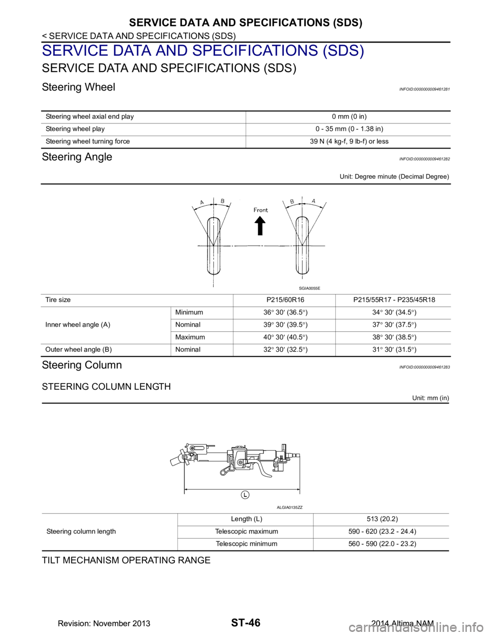
Steering WheelINFOID:0000000009461281
Steering AngleINFOID:0000000009461282
Unit: Degree minute (Decimal Degree)
Steering ColumnINFOID:0000000009461283
STEERING COLUMN LENGTH
Unit: mm (in)
TILT MECHANISM OPERATING RANGE
Steering wheel axial end play 0 mm (0 in)
Steering wheel play 0 - 35 mm (0 - 1.38 in)
Steering wheel turning force 3 9 N (4 kg-f, 9 lb-f) or less
Tire size P215/60R16 P215/55R17 - P235/45R18
Inner wheel angle (A) Minimum 36
° 30 ′ (36.5 °)34 ° 30 ′ (34.5 °)
Nominal 39 ° 30 ′ (39.5 °)37 ° 30 ′ (37.5 °)
Maximum 40 ° 30 ′ (40.5 °)38 ° 30 ′ (38.5 °)
Outer wheel angle (B) Nominal 32 ° 30 ′ (32.5 °)31 ° 30 ′ (31.5 °)
SGIA0055E
Steering column length Length (L) 513 (20.2)
Telescopic maximum 590 - 620 (23.2 - 24.4) Telescopic minimum 560 - 590 (22.0 - 23.2)
ALGIA0135ZZ
Revision: November 20132014 Altima NAMRevision: November 20132014 Altima NAM
Page 4150 of 4801
SERVICE DATA AND SPECIFICATIONS (SDS)ST-47
< SERVICE DATA AND SPECIFICATIONS (SDS)
C
D E
F
H I
J
K L
M A
B
ST
N
O P
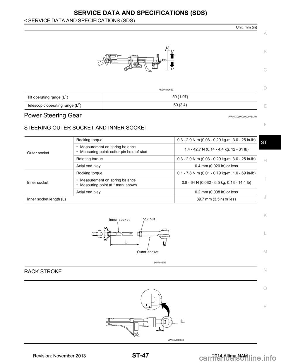
Unit: mm (in)
Power Steering GearINFOID:0000000009461284
STEERING OUTER SOCK ET AND INNER SOCKET
RACK STROKE
Tilt operating range (L1) 50 (1.97)
Telescopic operating range (L
2) 60 (2.4)
ALGIA0136ZZ
Outer socketRocking torque 0.3 - 2.9 N·m (0.0
3 - 0.29 kg-m, 3.0 - 25 in-lb)
• Measurement on spring balance
• Measuring point: cotter pin hole of stud 1.4 - 42.7 N (0.14 - 4.4 kg, 12 - 31 lb)
Rotating torque 0.3 - 2.9 N·m (0.03 - 0.29 kg-m, 3.0 - 25 in-lb)
Axial end play 0.4 mm (0.020 in) or less
Inner socket Rocking torque 0.1 - 7.8 N·m (0.0
1 - 0.79 kg-m, 1.0 - 69 in-lb)
• Measurement on spring balance
• Measuring point at * mark shown 0.8 - 64 N (0.082 - 6.5 kg, 0.18 - 14.4 lb)
Axial end play 0.2 mm (0.008 in) or less
Inner socket length (L) 89.7 mm (3.5in) or less
SGIA0167E
AWGIA0003GB
Revision: November 20132014 Altima NAMRevision: November 20132014 Altima NAM
Trending: 4WD, jump start, suspension, radio antenna, fuel pressure, remove seats, engine coolant
