wheel size NISSAN TEANA 2014 Service Manual
[x] Cancel search | Manufacturer: NISSAN, Model Year: 2014, Model line: TEANA, Model: NISSAN TEANA 2014Pages: 4801, PDF Size: 51.2 MB
Page 5 of 4801
QUICK REFERENCE CHART: ALTIMA
2014
Drive BeltINFOID:0000000010112420
DRIVE BELT
Spark PlugINFOID:0000000010112421
SPARK PLUG
Unit: mm (in)
*: Always check with the Parts Department for the latest parts information.
Front Wheel Alignment (Unladen*1)INFOID:0000000010112418
UNITED STATES
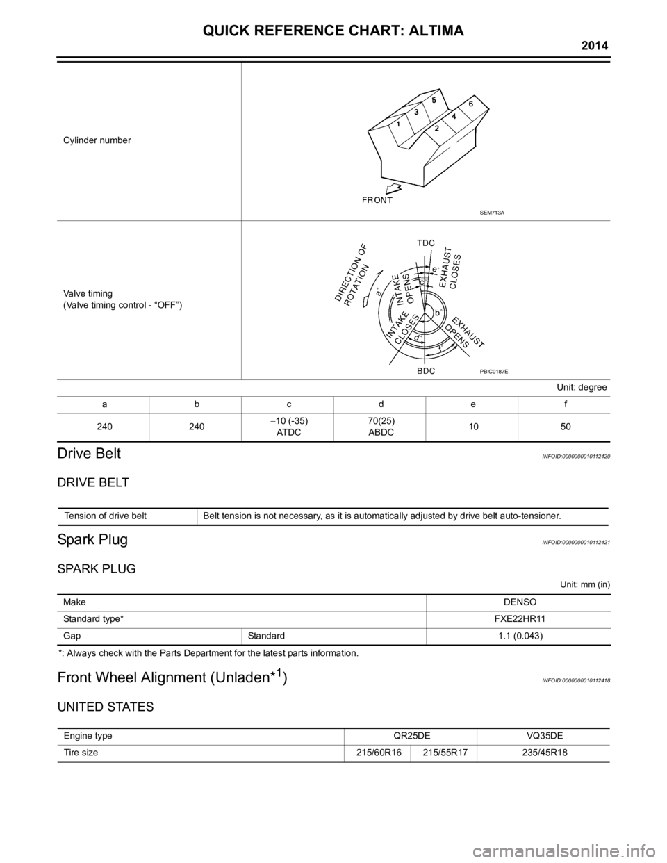
Cylinder number
Valve timing
(Valve timing control - “OFF”)Unit: degree
abcde f
240 240−
10 (-35)
AT D C 70(25)
ABDC 10
50
SEM713A
PBIC0187E
Tension of drive belt Belt tension is not necessary, as it is automatically adjusted by drive belt auto-tensioner.
Make DENSO
Standard type* FXE22HR11
Gap Standard 1.1 (0.043)
Engine type QR25DEVQ35DE
Tire size 215/60R16 215/55R17235/45R18
Page 151 of 4801
![NISSAN TEANA 2014 Service Manual
PRECAUTIONSBRC-5
< PRECAUTION > [VDC/TCS/ABS]
C
D E
G H
I
J
K L
M A
B
BRC
N
O P
Precaution for Brake ControlINFOID:0000000009463736
• During ABS operation, the brake pedal may vibrate lightly and NISSAN TEANA 2014 Service Manual
PRECAUTIONSBRC-5
< PRECAUTION > [VDC/TCS/ABS]
C
D E
G H
I
J
K L
M A
B
BRC
N
O P
Precaution for Brake ControlINFOID:0000000009463736
• During ABS operation, the brake pedal may vibrate lightly and](/img/5/57390/w960_57390-150.png)
PRECAUTIONSBRC-5
< PRECAUTION > [VDC/TCS/ABS]
C
D E
G H
I
J
K L
M A
B
BRC
N
O P
Precaution for Brake ControlINFOID:0000000009463736
• During ABS operation, the brake pedal may vibrate lightly and a mechanical noise may be heard. This is normal.
• Just after starting vehicle, the brake pedal may vibrate or a motor operating noise may be heard from engine
compartment. This is a normal status of operation check.
• Stopping distance may be longer than that of vehicles without ABS when vehicle drives on rough, gravel, or
snow-covered (fresh, deep snow) roads.
• When an error is indicated by ABS or another warning lamp, collect all necessary information from customer
(what symptoms are present under what conditions) and check for simple causes before starting diagnosis.
Besides electrical system inspection, check boos ter operation, brake fluid level, and fluid leaks.
• If incorrect tire sizes or types are installed on the vehicle or brake pads are not Genuine NISSAN parts, stop-
ping distance or steering stability may deteriorate.
• If there is a radio, antenna or related wiring near control module, ABS function may have a malfunction or
error.
• If aftermarket parts (car stereo, CD player, etc.) have been installed, check for incidents such as harness pinches, open circuits or improper wiring.
• If the following components are replaced with non-genuine components or modified, the VDC OFF indicator
lamp and SLIP indicator lamp may turn on or the VDC system may not operate properly. Components
related to suspension (shock absorbers, struts, springs , bushings, etc.), tires, wheels (exclude specified
size), components related to brake system (pads, roto rs, calipers, etc.), components related to engine (muf-
fler, ECM, etc.), components related to body reinforcement (roll bar, tower bar, etc.).
• Driving with broken or excessively worn suspensi on components, tires or brake system components may
cause the VDC OFF indicator lamp and the SLIP indicator lamp to turn on, and the VDC system may not
operate properly.
• When the TCS or VDC is activated by sudden acceleration or sudden turn, some noise may occur. The
noise is a result of the normal operation of the TCS and VDC.
• When driving on roads which have extreme slopes (such as mountainous roads) or high banks (such as sharp curves on a freeway), the VDC may not operate no rmally, or the VDC warning lamp and the SLIP indi-
cator lamp may turn on. This is not a problem if normal operation can be resumed after restarting the engine.
• Sudden turns (such as spin turns, acceleration turns), drifting, etc. with VDC turned off may cause the yaw rate/side/decel G sensor to indicate a problem. This is not a problem if normal operation can be resumed
after restarting the engine.
Precaution for CAN SystemINFOID:0000000009463737
• Do not apply voltage of 7.0V or higher to terminal to be measured.
• Maximum open terminal voltage of tester in use must be less than 7.0V.
• Before checking harnesses, turn ignition switch OFF and disconnect battery negative cable.
• Area to be repaired must be soldered and wrapped with tape. Make sure that fraying of twisted wire is within 110 mm (4.33 in).
PKIA0306E
Revision: November 20132014 Altima NAMRevision: November 20132014 Altima NAM
Page 156 of 4801
![NISSAN TEANA 2014 Service Manual
BRC-10
< SYSTEM DESCRIPTION >[VDC/TCS/ABS]
COMPONENT PARTS
Suction Valve 1, Suction Valve 2
Supplies the brake fluid from master cylinder to t
he pump, when VDC function and TCS function are activate NISSAN TEANA 2014 Service Manual
BRC-10
< SYSTEM DESCRIPTION >[VDC/TCS/ABS]
COMPONENT PARTS
Suction Valve 1, Suction Valve 2
Supplies the brake fluid from master cylinder to t
he pump, when VDC function and TCS function are activate](/img/5/57390/w960_57390-155.png)
BRC-10
< SYSTEM DESCRIPTION >[VDC/TCS/ABS]
COMPONENT PARTS
Suction Valve 1, Suction Valve 2
Supplies the brake fluid from master cylinder to t
he pump, when VDC function and TCS function are activated.
Return Check Valve
Returns the brake fluid from brake caliper and wheel cy linder to master cylinder by bypassing orifice of each
valve when brake is released.
Reservoir
Temporarily reserves the brake fluid drained from brake caliper, so that pressure efficiently decreases when
decreasing pressure of brake caliper and wheel cylinder.
Yaw rate/side/decel G sensor
Calculates the following information that affects the vehicle, and transmits a signal to ABS actuator and elec-
tric unit (control unit) via communication lines.
• Vehicle rotation angular velocity (yaw rate signal)
• Vehicle lateral acceleration (side G signal) and longitudinal acceleration (decel G signal)
Pressure Sensor
Detects the brake fluid pressure and transmits signal to ABS actuator and electric unit (control unit).
Wheel Sensor and Sensor RotorINFOID:0000000009463744
NOTE:
• Wheel sensor of front wheel is installed on steering knuckle.
• Sensor rotor of front wheel is integrated in wheel hub assembly.
• Wheel sensor of rear wheel is installed on back plate of rear brake.
• Sensor rotor of rear wheel is installed on rear brake drum.
• Never measure resistance and voltage value using a tester because sensor is active sensor.
• Downsize and weight reduction is aimed. IC for detection portion and magnet for sensor rotor are adopted.
• Power supply is supplied to detection portion so that magnetic field line is read. Magnetic field that is detected is converted to current
signal.
• When sensor rotor rotates, magnetic field changes. Magnetic field change is converted to current signals (rectangular wave) and is
transmitted to ABS actuator and el ectric unit (control unit). Change
of magnetic field is proportional to wheel speed.
Stop Lamp SwitchINFOID:0000000009463745
Detects the operation status of brake pedal and transmits converted electric signal to ABS actuator and elec-
tric unit (control unit).
Steering Angle SensorINFOID:0000000009463746
Detects the following information and transmits steering angl e signal to ABS actuator and electric unit (control
unit) via CAN communication.
• Steering wheel rotation amount
• Steering wheel rotation angular velocity
• Steering wheel rotation direction
Brake Fluid Level SwitchINFOID:0000000009463747
Detects the brake fluid level in reservoir tank and transmi ts converted electric signal from combination meter to
ABS actuator and electric unit (control unit) via CAN communication.
Vacuum SensorINFOID:0000000009463748
Detects the vacuum in brake booster and transmits conver ted electric signal to ABS actuator and electric unit
(control unit).
JPFIC0131GB
Revision: November 20132014 Altima NAMRevision: November 20132014 Altima NAM
Page 222 of 4801
![NISSAN TEANA 2014 Service Manual
BRC-76
< DTC/CIRCUIT DIAGNOSIS >[VDC/TCS/ABS]
C1115 ABS SENSOR
[ABNORMAL SIGNAL]
C1115 ABS SENSOR [ABNORMAL SIGNAL]
DTC LogicINFOID:0000000009463782
DTC DETECTION LOGIC
DTC CONFIRMATION PROCEDURE
1 NISSAN TEANA 2014 Service Manual
BRC-76
< DTC/CIRCUIT DIAGNOSIS >[VDC/TCS/ABS]
C1115 ABS SENSOR
[ABNORMAL SIGNAL]
C1115 ABS SENSOR [ABNORMAL SIGNAL]
DTC LogicINFOID:0000000009463782
DTC DETECTION LOGIC
DTC CONFIRMATION PROCEDURE
1](/img/5/57390/w960_57390-221.png)
BRC-76
< DTC/CIRCUIT DIAGNOSIS >[VDC/TCS/ABS]
C1115 ABS SENSOR
[ABNORMAL SIGNAL]
C1115 ABS SENSOR [ABNORMAL SIGNAL]
DTC LogicINFOID:0000000009463782
DTC DETECTION LOGIC
DTC CONFIRMATION PROCEDURE
1.CHECK SELF DIAGNOSTIC RESULT
With CONSULT.
1. Start engine and drive vehicle at approximately 30 km /h (19 MPH) or more for approximately 1 minute.
2. Perform self diagnostic result.
Is DTC C1115 detected?
YES >> Proceed to diagnosis procedure. Refer to BRC-76, "Diagnosis Procedure".
NO >> Inspection End.
Diagnosis ProcedureINFOID:0000000009463783
Regarding Wiring Diagram information, refer to BRC-47, "Wiring Diagram".
CAUTION:
Do not check between wheel sensor terminals.
1.CONNECTOR INSPECTION
1. Disconnect ABS actuator and electric unit (contro l unit) connector E54 and wheel sensor connector of
wheel with DTC.
2. Check terminals for deformation, disconnection, looseness or damage.
Is the inspection result normal?
YES >> GO TO 2.
NO >> Repair or replace as necessary.
2.CHECK WHEEL SENSOR OUTPUT SIGNAL
1. Connect ABS active wheel sensor tester (J- 45741) to wheel sensor using appropriate adapter.
2. Turn on the ABS active wheel sensor tester power switch. NOTE:
The green POWER indicator should illuminate. If the POWER indicator does not illuminate, replace the
battery in the ABS active wheel sensor tester before proceeding.
3. Spin the wheel of the vehicle by hand and observe the red SENSOR indicator on the ABS active wheel
sensor tester. The red SENSOR indicator should flash on and off to indicate an output signal.
NOTE:
If the red SENSOR indicator illuminates but does not flash, reverse the polarity of the tester leads and
retest.
Does the ABS active wheel sensor tester detect a signal?
YES >> GO TO 3.
NO >> Replace the wheel sensor. Refer to BRC-124, "Removal and Installation - Front Wheel Sensor"
or
BRC-125, "Removal and Installation - Rear Wheel Sensor"
.
3.CHECK TIRES
Check the inflation pressure, wear and size of each tire.
Is the inspection result normal?
DTC Display Item Malfunction detected condition Possible causes
C 111 5 ABS SENSOR
[ABNORMAL SIGNAL] When difference in wheel speed between any wheel
and others is detected while the vehicle is driven, be-
cause of installation of tires other than specified. • Harness or connector
• Wheel sensor
• Sensor rotor
• ABS actuator and electric unit (control unit)
Revision: November 20132014 Altima NAMRevision: November 20132014 Altima NAM
Page 390 of 4801
![NISSAN TEANA 2014 Service Manual
CO-10
< SYSTEM DESCRIPTION >[QR25DE]
OVERHEATING CAUSE ANALYSIS
Except cool-
ing system
parts mal-
function — Overload on engine
Abusive driving
High engine rpm under no
load
Driving in low g NISSAN TEANA 2014 Service Manual
CO-10
< SYSTEM DESCRIPTION >[QR25DE]
OVERHEATING CAUSE ANALYSIS
Except cool-
ing system
parts mal-
function — Overload on engine
Abusive driving
High engine rpm under no
load
Driving in low g](/img/5/57390/w960_57390-389.png)
CO-10
< SYSTEM DESCRIPTION >[QR25DE]
OVERHEATING CAUSE ANALYSIS
Except cool-
ing system
parts mal-
function — Overload on engine
Abusive driving
High engine rpm under no
load
Driving in low gear for ex-
tended time
Driving at extremely high
speed
Powertrain sy stem malfunc-
tion
—
Installed improper size
wheels and tires
Dragging brakes
Improper ignition timing
Blocked or restricted air
flow Blocked radiator grille Installed car brassiere
—
Mud contamination or paper
clogging
Blocked bumper
Blocked radiator
Blocked condenser
Installed large fog lamp
Symptom Check items
Revision: November 20132014 Altima NAM
Page 414 of 4801
![NISSAN TEANA 2014 Service Manual
CO-34
< SYSTEM DESCRIPTION >[VQ35DE]
OVERHEATING CAUSE ANALYSIS
Except cool-
ing system
parts mal-
function — Overload on engine
Abusive driving
High engine rpm under no
load
Driving in low g NISSAN TEANA 2014 Service Manual
CO-34
< SYSTEM DESCRIPTION >[VQ35DE]
OVERHEATING CAUSE ANALYSIS
Except cool-
ing system
parts mal-
function — Overload on engine
Abusive driving
High engine rpm under no
load
Driving in low g](/img/5/57390/w960_57390-413.png)
CO-34
< SYSTEM DESCRIPTION >[VQ35DE]
OVERHEATING CAUSE ANALYSIS
Except cool-
ing system
parts mal-
function — Overload on engine
Abusive driving
High engine rpm under no
load
Driving in low gear for ex-
tended time
Driving at extremely high
speed
Powertrain sy stem malfunc-
tion
—
Installed improper size
wheels and tires
Dragging brakes
Improper ignition timing
Blocked or restricted air
flow Blocked bumper Blocked air flow
—
Blocked radiator grille
Installed car brassiere
Mud contamination or paper
clogging
Blocked radiator Blocked air flow
Blocked condenser
Installed large fog lamp
Symptom Check items
Revision: November 20132014 Altima NAM
Page 2526 of 4801
SERVICE DATA AND SPECIFICATIONS (SDS)FSU-25
< SERVICE DATA AND SPECIFICATIONS (SDS)
C
D
F
G H
I
J
K L
M A
B
FSU
N
O P
SERVICE DATA AND SPECIFICATIONS (SDS)
SERVICE DATA AND SPECIFICATIONS (SDS)
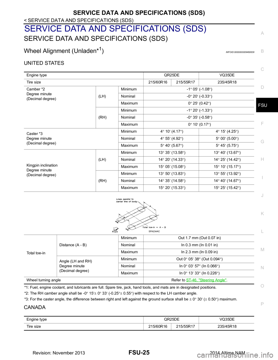
Wheel Alignment (Unladen*1)INFOID:0000000009460639
UNITED STATES
*1: Fuel, engine coolant, and lubricants are full. Spare tire, jack, hand tools, and mats are in designated positions.
*2: The RH camber angle shall be -0 ° 15 ′± 0 ° 33 ′ (-0.25 °± 0.55 °) with respect to the LH camber angle.
*3: For the caster angle, the difference between right and left against the ground surface shall be ± 0 ° 30 ′ ( ± 0.50 °) maximum.
CANADA
Engine type QR25DE VQ35DE
Tire size 215/60R16 215/55R17 235/45R18
Camber *2
Degree minute
(Decimal degree) (LH)Minimum -1
° 05 ′ (-1.08 °)
Nominal -0 ° 20 ′ (-0.33 °)
Maximum 0 ° 25 ′ (0.42 °)
(RH) Minimum -1
° 20 ′ (-1.33 °)
Nominal -0 ° 35 ′ (-0.58 °)
Maximum 0 ° 10 ′ (0.17 °)
Caster *3
Degree minute
(Decimal degree) Minimum 4
° 10 ′ (4.17 °)4 ° 15 ′ (4.25 °)
Nominal 4 ° 55 ′ (4.92 °)5 ° 00 ′ (5.00 °)
Maximum 5 ° 40 ′ (5.67 °)5 ° 45 ′ (5.75 °)
Kingpin inclination
Degree minute
(Decimal degree) (LH)
Minimum 13
° 35 ′ (13.58 °)13 ° 40
′ (13.67 °)
Nominal 14 ° 20 ′ (14.33 °)14 ° 25 ′ (14.42 °)
Maximum 15 ° 05 ′ (15.08 °)15 ° 10 ′ (15.17 °)
(RH) Minimum 13
° 50 ′ (13.83 °)13 ° 55 ′ (13.92 °)
Nominal 14 ° 35 ′ (14.58 °)14 ° 40 ′ (14.67 °)
Maximum 15 ° 20 ′ (15.33 °)15 ° 25 ′ (15.42 °)
To t a l t o e - i n Distance (A - B)
Minimum Out 1.7 mm (Out 0.07 in)
Nominal In 0.3 mm (In 0.01 in)
Maximum In 2.3 mm (In 0.09 in)
Angle (LH and RH)
Degree minute
(Decimal degree) Minimum Out 0
° 05 ′ 38 ″ (Out 0.094 °)
Nominal In 0 ° 03 ′ 57 ″ (In 0.066 °)
Maximum In 0 ° 13 ′ 33 ″ (In 0.226 °)
Wheel turning angle Refer to ST-46, "Steering Angle"
.
SFA234AC
Engine type QR25DE VQ35DE
Tire size 215/60R16 215/55R17 235/45R18
Revision: November 20132014 Altima NAM
Page 2553 of 4801
IDENTIFICATION INFORMATIONGI-25
< VEHICLE INFORMATION >
C
D E
F
G H
I
J
K L
M B
GI
N
O P
VQ35DE
CVT NumberINFOID:0000000009462988
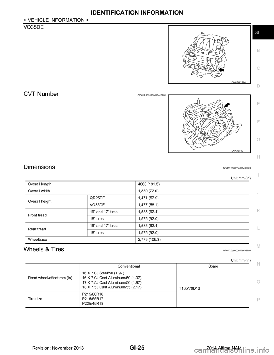
DimensionsINFOID:0000000009462989
Unit:mm (in)
Wheels & TiresINFOID:0000000009462990
Unit:mm (in)
ALAIA0013ZZ
LAIA0074E
Overall length 4863 (191.5)
Overall width 1,830 (72.0)
Overall height QR25DE 1,471 (57.9)
VQ35DE 1,477 (58.1)
Front tread 16” and 17” tires 1,585 (62.4)
18” tires 1,575 (62.0)
Rear tread 16” and 17” tires 1,585 (62.4)
18” tires 1,575 (62.0)
Wheelbase 2,775 (109.3)
Conventional Spare
Road wheel/offset mm (in) 16 X 7.0J Steel/50 (1.97)
16 X 7.0J Cast Aluminum/50 (1.97)
17 X 7.5J Cast Aluminum/50 (1.97)
18 X 7.5J Cast Aluminum/55 (2.17) T135/70D16
Tire size P215/60R16
P215/55R17
P235/45R18
Revision: November 20132014 Altima NAMRevision: November 20132014 Altima NAM
Page 3223 of 4801
CHASSIS AND BODY MAINTENANCEMA-39
< PERIODIC MAINTENANCE >
C
D E
F
G H
I
J
K L
M B
MA
N
O A
WHEELS : AdjustmentINFOID:0000000009464575
BALANCING WHEELS (ADH
ESIVE WEIGHT TYPE)
Preparation Before Adjustment
Remove inner and outer balance weights from the r oad wheel. Using releasing agent, remove double-faced
adhesive tape from the road wheel.
CAUTION:
• Be careful not scratch the road wheel during removal.
• After removing double-faced adhesive tape, wipe clean traces of releasing agent from the road
wheel.
Wheel Balance Adjustment
• If a balancer machine has an adhesive weight mode setting, select the adhesive weight mode setting and skip Step 2. below. If a balancer machine only has the clip-on (rim flange) weight mode setting, follow Step 2.
to calculate the correct size adhesive weight.
1. Set road wheel on balancer machine using the cent er hole as a guide. Start the balancer machine.
2. For balancer machines that only have a clip-on (rim fl ange) weight mode setting, follow this step to calcu-
late the correct size adhesive weight to use. W hen inner and outer imbalance values are shown on the
balancer machine indicator, multiply outer imbalance value by 5/3 (1.67) to determine balance weight that
should be used. Select the outer balance weight with a value closest to the calculated value above and
install in to the designated outer position of, or at the designated angle in relation to the road wheel.
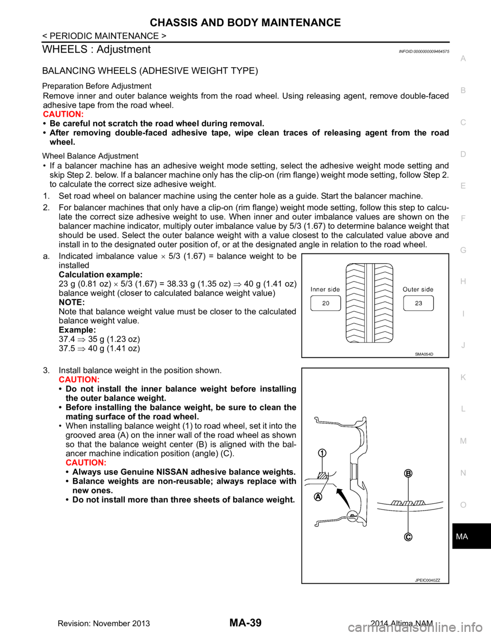
a. Indicated imbalance value × 5/3 (1.67) = balance weight to be
installed
Calculation example:
23 g (0.81 oz) × 5/3 (1.67) = 38.33 g (1.35 oz) ⇒ 40 g (1.41 oz)
balance weight (closer to calculated balance weight value)
NOTE:
Note that balance weight value must be closer to the calculated
balance weight value.
Example:
37.4 ⇒ 35 g (1.23 oz)
37.5 ⇒ 40 g (1.41 oz)
3. Install balance weight in the position shown. CAUTION:
• Do not install the inner bala nce weight before installing
the outer balance weight.
• Before installing the balance weight, be sure to clean the mating surface of the road wheel.
• When installing balance weight (1) to road wheel, set it into the
grooved area (A) on the inner wall of the road wheel as shown
so that the balance weight cent er (B) is aligned with the bal-
ancer machine indication position (angle) (C).
CAUTION:
• Always use Genuine NISSAN adhesive balance weights.
• Balance weights are non-re usable; always replace with
new ones.
• Do not install more than th ree sheets of balance weight.
SMA054D
JPEIC0040ZZ
Revision: November 20132014 Altima NAM
Page 3734 of 4801
SERVICE DATA AND SPECIFICATIONS (SDS)RSU-17
< SERVICE DATA AND SPECIFICATIONS (SDS)
C
D
F
G H
I
J
K L
M A
B
RSU
N
O P
SERVICE DATA AND SPECIFICATIONS (SDS)
SERVICE DATA AND SPECIFICATIONS (SDS)
General Specification (Rear)INFOID:0000000009464468
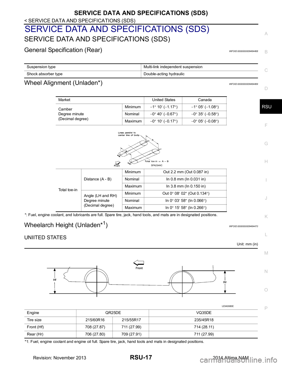
Wheel Alignment (Unladen*)INFOID:0000000009464469
*: Fuel, engine coolant, and lubricants are full. Spare tire, jack, hand tools, and mats are in designated positions.
Wheelarch Height (Unladen*1)INFOID:0000000009464470
UNIITED STATES
Unit: mm (in)
*1: Fuel, engine coolant and engine oil full. Spare tire, jack, hand tools and mats in designated positions. Suspension type Multi-link independent suspension
Shock absorber type Double-acting hydraulic
Market United States Canada
Camber
Degree minute
(Decimal degree) Minimum
−1° 10 ′ ( −1.17 °) −1 ° 05 ′ ( −1.08 °)
Nominal −0° 40 ′ ( −0.67 °) −0 ° 35 ′ ( −0.58 °)
Maximum −0° 10 ′ ( −0.17 °) −0 ° 05 ′ ( −0.08 °)
Total toe-in Distance (A - B)
Minimum Out 2.2 mm (Out 0.087 in)
Nominal In 0.8 mm (In 0.031 in)
Maximum In 3.8 mm (In 0.150 in)
Angle (LH and RH)
Degree minute
(Decimal degree) Minimum Out 0
° 08 ′ 02 ″ (Out 0.134 °)
Nominal In 0 ° 03 ′ 58 ″ (In 0.066 °)
Maximum In 0 ° 15 ′ 58 ″ (In 0.266 °)
SFA234AC
Engine QR25DE VQ35DE
Tire size 215/60R16 215/55R17 235/45R18
Front (Hf) 708 (27.87) 711 (27.99) 714 (28.11)
Rear (Hr) 706 (27.80) 709 (27.91) 711 (27.99)
LEIA0085E
Revision: November 20132014 Altima NAM