NISSAN TERRANO 2002 Service Repair Manual
TERRANO 2002
NISSAN
NISSAN
https://www.carmanualsonline.info/img/5/57393/w960_57393-0.png
NISSAN TERRANO 2002 Service Repair Manual
Trending: suspension, catalytic converter, oil level, light, compression ratio, jump start terminals, power steering fluid
Page 1051 of 1767
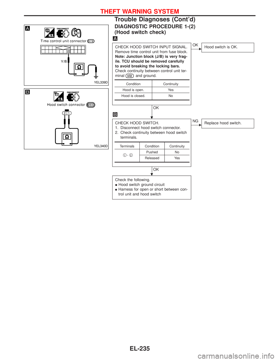
DIAGNOSTIC PROCEDURE 1-(2)
(Hood switch check)
CHECK HOOD SWITCH INPUT SIGNAL.
Remove time control unit from fuse block.
Note: Junction block (J/B) is very frag-
ile. TCU should be removed carefully
to avoid breaking the locking bars.
Check continuity between control unit ter-
minal
U32and ground.
OK
EOK
Hood switch is OK.
CHECK HOOD SWITCH.
1. Disconnect hood switch connector.
2. Check continuity between hood switch
terminals.
OK
ENG
Replace hood switch.
Check the following.
IHood switch ground circuit
IHarness for open or short between con-
trol unit and hood switch
Condition Continuity
Hood is open. Yes
Hood is closed. No
Terminals Condition Continuity
q
1-q2Pushed No
Released Yes
YEL339D
YEL340D
H
H
THEFT WARNING SYSTEM
Trouble Diagnoses (Cont'd)
EL-235
Page 1052 of 1767
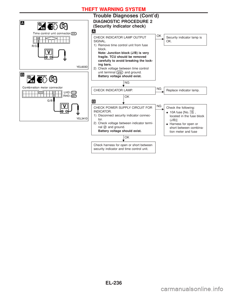
DIAGNOSTIC PROCEDURE 2
(Security indicator check)
CHECK INDICATOR LAMP OUTPUT
SIGNAL.
1) Remove time control unit from fuse
block.
Note: Junction block (J/B) is very
fragile. TCU should be removed
carefully to avoid breaking the lock-
ing bars.
2) Check voltage between time control
unit terminal
U18and ground.
Battery voltage should exist.
NG
EOK
Security indicator lamp is
OK.
CHECK INDICATOR LAMP.
OK
ENG
Replace indicator lamp.
CHECK POWER SUPPLY CIRCUIT FOR
INDICATOR.
1) Disconnect security indicator connec-
tor.
2) Check voltage between indicator termi-
nalq
27and ground.
Battery voltage should exist.
OK
ENG
Check the following:
I10A fuse [No.
16,
located in the fuse block
(J/B)]
IHarness for open or
short between combina-
tion meter and fuse
Check harness for open or short between
security indicator and time control unit.
YEL603D
YEL341D
H
H
H
THEFT WARNING SYSTEM
Trouble Diagnoses (Cont'd)
EL-236
Page 1053 of 1767
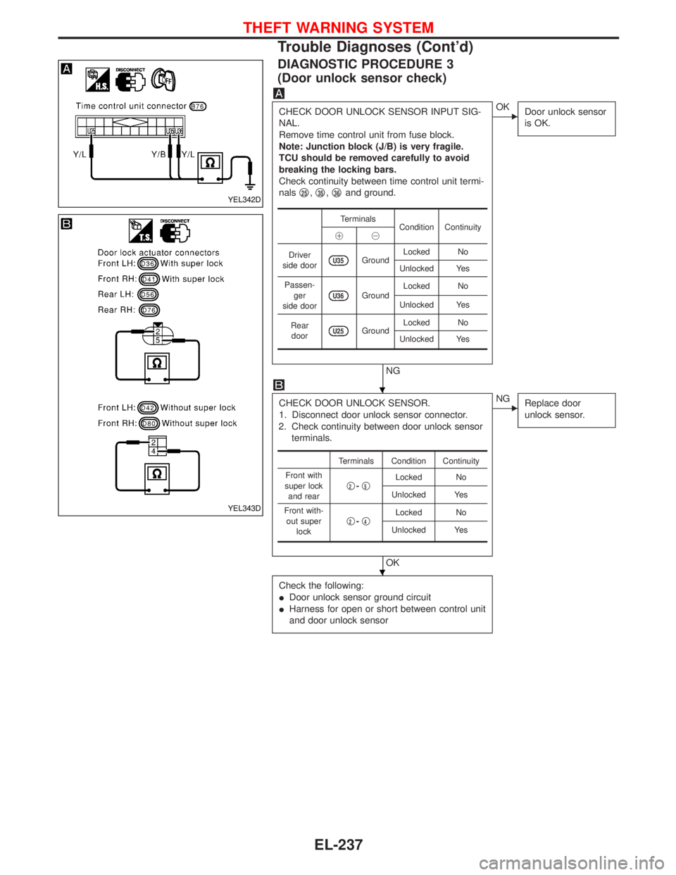
DIAGNOSTIC PROCEDURE 3
(Door unlock sensor check)
CHECK DOOR UNLOCK SENSOR INPUT SIG-
NAL.
Remove time control unit from fuse block.
Note: Junction block (J/B) is very fragile.
TCU should be removed carefully to avoid
breaking the locking bars.
Check continuity between time control unit termi-
nalsq
25,q35,q36and ground.
NG
EOK
Door unlock sensor
is OK.
CHECK DOOR UNLOCK SENSOR.
1. Disconnect door unlock sensor connector.
2. Check continuity between door unlock sensor
terminals.
OK
ENG
Replace door
unlock sensor.
Check the following:
IDoor unlock sensor ground circuit
IHarness for open or short between control unit
and door unlock sensor
Terminals
Condition Continuity
!@
Driver
side door
U35GroundLocked No
Unlocked Yes
Passen-
ger
side door
U36GroundLocked No
Unlocked Yes
Rear
door
U25GroundLocked No
Unlocked Yes
Terminals Condition Continuity
Front with
super lock
and rearq
2-q5Locked No
Unlocked Yes
Front with-
out super
lockq
2-q4Locked No
Unlocked Yes
YEL342D
YEL343D
H
H
THEFT WARNING SYSTEM
Trouble Diagnoses (Cont'd)
EL-237
Page 1054 of 1767
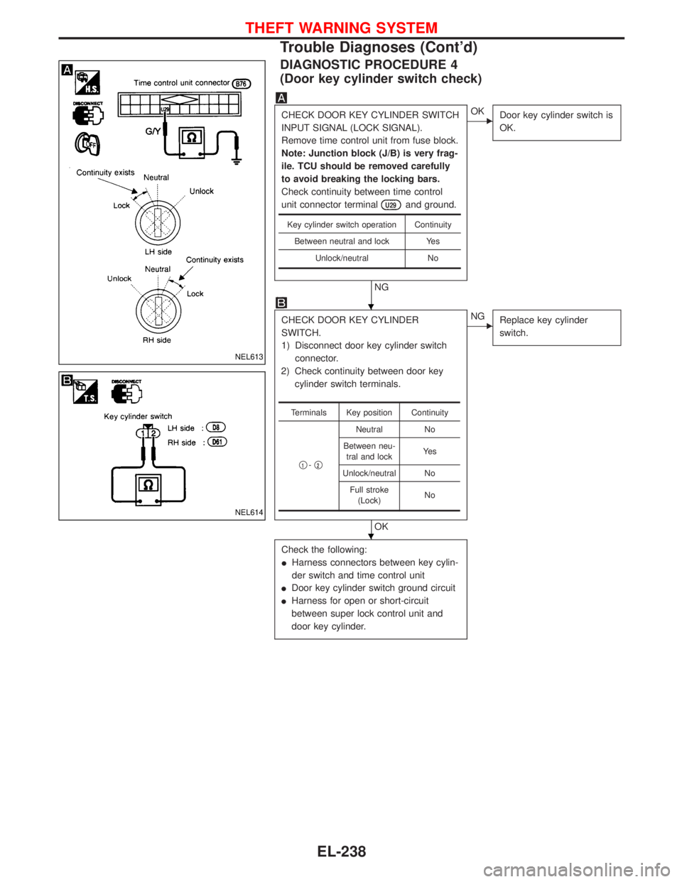
DIAGNOSTIC PROCEDURE 4
(Door key cylinder switch check)
CHECK DOOR KEY CYLINDER SWITCH
INPUT SIGNAL (LOCK SIGNAL).
Remove time control unit from fuse block.
Note: Junction block (J/B) is very frag-
ile. TCU should be removed carefully
to avoid breaking the locking bars.
Check continuity between time control
unit connector terminal
U29and ground.
NG
EOK
Door key cylinder switch is
OK.
CHECK DOOR KEY CYLINDER
SWITCH.
1) Disconnect door key cylinder switch
connector.
2) Check continuity between door key
cylinder switch terminals.
OK
ENG
Replace key cylinder
switch.
Check the following:
IHarness connectors between key cylin-
der switch and time control unit
IDoor key cylinder switch ground circuit
IHarness for open or short-circuit
between super lock control unit and
door key cylinder.
Key cylinder switch operation Continuity
Between neutral and lock Yes
Unlock/neutral No
Terminals Key position Continuity
q
1-q2
Neutral No
Between neu-
tral and lockYe s
Unlock/neutral No
Full stroke
(Lock)No
NEL613
NEL614
H
H
THEFT WARNING SYSTEM
Trouble Diagnoses (Cont'd)
EL-238
Page 1055 of 1767
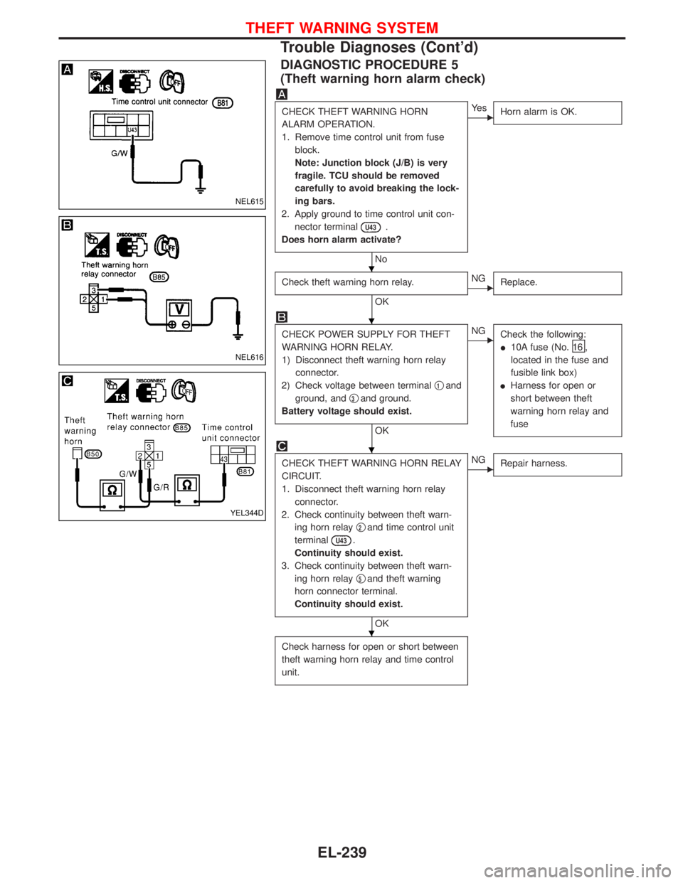
DIAGNOSTIC PROCEDURE 5
(Theft warning horn alarm check)
CHECK THEFT WARNING HORN
ALARM OPERATION.
1. Remove time control unit from fuse
block.
Note: Junction block (J/B) is very
fragile. TCU should be removed
carefully to avoid breaking the lock-
ing bars.
2. Apply ground to time control unit con-
nector terminal
U43.
Does horn alarm activate?
No
EYe s
Horn alarm is OK.
Check theft warning horn relay.
OK
ENG
Replace.
CHECK POWER SUPPLY FOR THEFT
WARNING HORN RELAY.
1) Disconnect theft warning horn relay
connector.
2) Check voltage between terminalq
1and
ground, andq
3and ground.
Battery voltage should exist.
OK
ENG
Check the following:
I10A fuse (No.
16 ,
located in the fuse and
fusible link box)
IHarness for open or
short between theft
warning horn relay and
fuse
CHECK THEFT WARNING HORN RELAY
CIRCUIT.
1. Disconnect theft warning horn relay
connector.
2. Check continuity between theft warn-
ing horn relayq
2and time control unit
terminal
U43.
Continuity should exist.
3. Check continuity between theft warn-
ing horn relayq
5and theft warning
horn connector terminal.
Continuity should exist.
OK
ENG
Repair harness.
Check harness for open or short between
theft warning horn relay and time control
unit.
NEL615
NEL616
YEL344D
H
H
H
H
THEFT WARNING SYSTEM
Trouble Diagnoses (Cont'd)
EL-239
Page 1056 of 1767
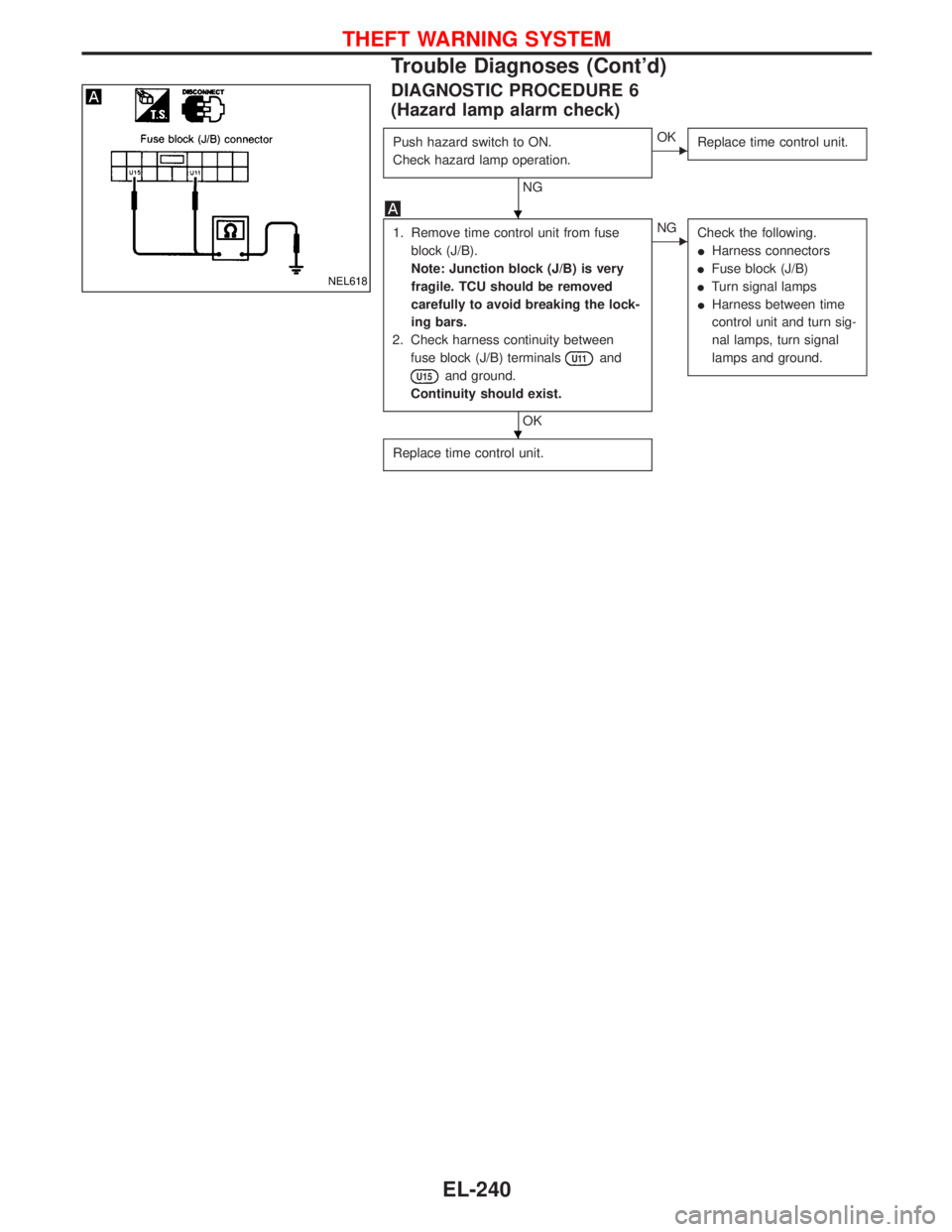
DIAGNOSTIC PROCEDURE 6
(Hazard lamp alarm check)
Push hazard switch to ON.
Check hazard lamp operation.
NG
EOK
Replace time control unit.
1. Remove time control unit from fuse
block (J/B).
Note: Junction block (J/B) is very
fragile. TCU should be removed
carefully to avoid breaking the lock-
ing bars.
2. Check harness continuity between
fuse block (J/B) terminals
U11and
U15and ground.
Continuity should exist.
OK
ENG
Check the following.
IHarness connectors
IFuse block (J/B)
ITurn signal lamps
IHarness between time
control unit and turn sig-
nal lamps, turn signal
lamps and ground.
Replace time control unit.
NEL618
H
H
THEFT WARNING SYSTEM
Trouble Diagnoses (Cont'd)
EL-240
Page 1057 of 1767
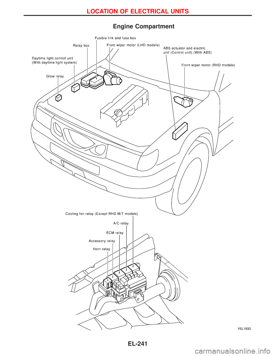
Engine Compartment
YEL193D
LOCATION OF ELECTRICAL UNITS
EL-241
Page 1058 of 1767
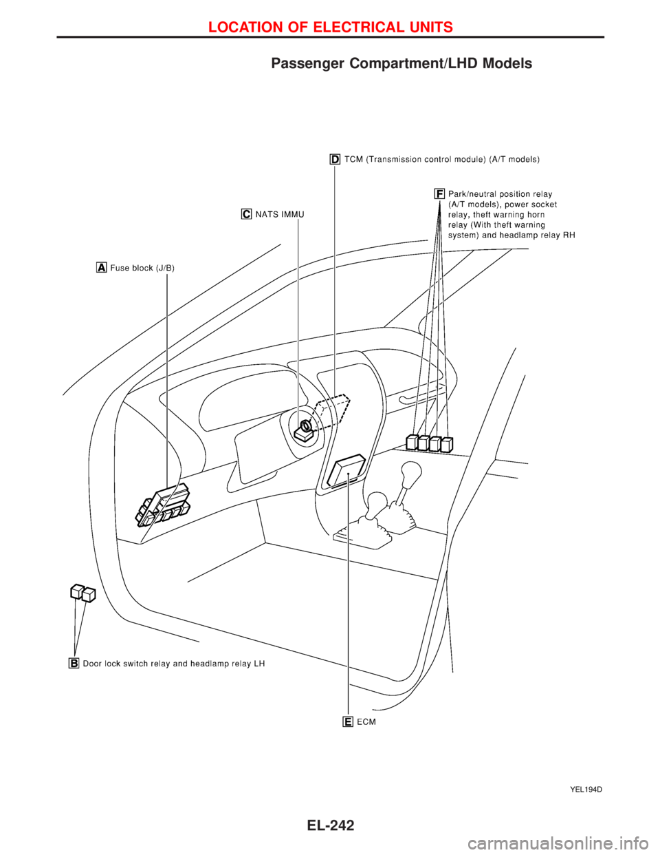
Passenger Compartment/LHD Models
YEL194D
LOCATION OF ELECTRICAL UNITS
EL-242
Page 1059 of 1767
YEL195D
LOCATION OF ELECTRICAL UNITS
Passenger Compartment/LHD Models (Cont'd)
EL-243
Page 1060 of 1767
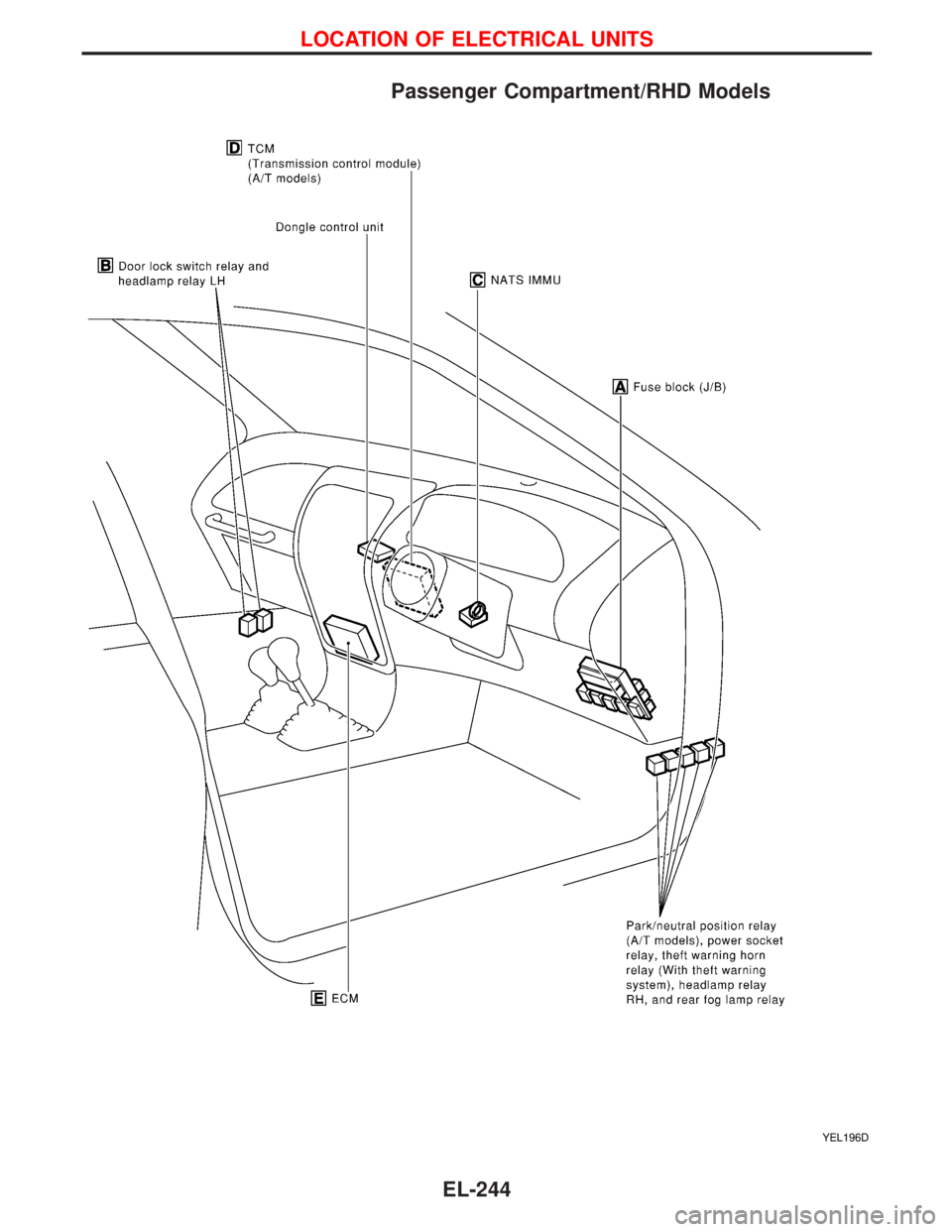
Passenger Compartment/RHD Models
YEL196D
LOCATION OF ELECTRICAL UNITS
EL-244
Trending: run flat, engine oil, manual radio set, check engine, load capacity, engine oil capacity, alternator replacement
