ECU NISSAN TERRANO 2002 Service Repair Manual
[x] Cancel search | Manufacturer: NISSAN, Model Year: 2002, Model line: TERRANO, Model: NISSAN TERRANO 2002Pages: 1767, PDF Size: 41.51 MB
Page 22 of 1767
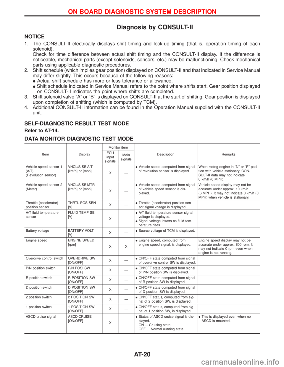
Diagnosis by CONSULT-II
NOTICE
1. The CONSULT-II electrically displays shift timing and lock-up timing (that is, operation timing of each
solenoid).
Check for time difference between actual shift timing and the CONSULT-II display. If the difference is
noticeable, mechanical parts (except solenoids, sensors, etc.) may be malfunctioning. Check mechanical
parts using applicable diagnostic procedures.
2. Shift schedule (which implies gear position) displayed on CONSULT-II and that indicated in Service Manual
may differ slightly. This occurs because of the following reasons:
IActual shift schedule has more or less tolerance or allowance,
IShift schedule indicated in Service Manual refers to the point where shifts start. Gear position displayed
on CONSULT-II indicates the point where shifts are completed.
3. Shift solenoid valve ªAº or ªBº is displayed on CONSULT-II at the start of shifting. Gear position is displayed
upon completion of shifting (which is computed by TCM).
4. Additional CONSULT-II information can be found in the Operation Manual supplied with the CONSULT-II
unit.
SELF-DIAGNOSTIC RESULT TEST MODE
Refer to AT-14.
DATA MONITOR DIAGNOSTIC TEST MODE
Item DisplayMonitor item
Description Remarks ECU
input
signalsMain
signals
Vehicle speed sensor 1
(A/T)
(Revolution sensor)VHCL/S SE×A/T
[km/h] or [mph]
XÐIVehicle speed computed from signal
of revolution sensor is displayed.When racing engine in ªNº or ªPº posi-
tion with vehicle stationary, CON-
SULT-II data may not indicate
0 km/h (0 MPH).
Vehicle speed sensor 2
(Meter)VHCL/S SE×MTR
[km/h] or [mph]
XÐIVehicle speed computed from signal
of vehicle speed sensor is dis-
played.Vehicle speed display may not be
accurate under approx. 10 km/h
(6 MPH). It may not indicate 0 km/h (0
MPH) when vehicle is stationary.
Throttle (accelerator)
position sensorTHRTL POS SEN
[V]XÐIThrottle (accelerator) position sen-
sor signal voltage is displayed.
A/T fluid temperature
sensorFLUID TEMP SE
[V]
XÐIA/T fluid temperature sensor signal
voltage is displayed.
ISignal voltage lowers as fluid tem-
perature rises.
Battery voltage BATTERY VOLT
[V]XÐISource voltage of TCM is displayed.
Engine speed ENGINE SPEED
[rpm]
XXIEngine speed, computed from
engine speed signal, is displayed.Engine speed display may not be
accurate under approx. 800 rpm. It
may not indicate 0 rpm even when
engine is not running.
Overdrive control switch OVERDRIVE SW
[ON/OFF]XÐION/OFF state computed from signal
of overdrive control SW is displayed.
P/N position switch P/N POSI SW
[ON/OFF]XÐION/OFF state computed from signal
of P/N position SW is displayed.
R position switch R POSITION SW
[ON/OFF]XÐION/OFF state computed from signal
of R position SW is displayed.
D position switch D POSITION SW
[ON/OFF]XÐION/OFF state computed from signal
of D position SW is displayed.
2 position switch 2 POSITION SW
[ON/OFF]XÐION/OFF status, computed from sig-
nal of 2 position SW, is displayed.
1 position switch 1 POSITION SW
[ON/OFF]XÐION/OFF status, computed from sig-
nal of 1 position SW, is displayed.
ASCD-cruise signal ASCD×CRUISE
[ON/OFF]
XÐIStatus of ASCD cruise signal is dis-
played.
ON ... Cruising state
OFF ... Normal running stateIThis is displayed even when no
ASCD is mounted.
ON BOARD DIAGNOSTIC SYSTEM DESCRIPTION
AT-20
Page 23 of 1767
![NISSAN TERRANO 2002 Service Repair Manual Item DisplayMonitor item
Description Remarks ECU
input
signalsMain
signals
ASCD-OD cut signal ASCD×OD CUT
[ON/OFF]
XÐIStatus of ASCD×OD release signal is
displayed.
ON ... OD released
OFF ... OD no NISSAN TERRANO 2002 Service Repair Manual Item DisplayMonitor item
Description Remarks ECU
input
signalsMain
signals
ASCD-OD cut signal ASCD×OD CUT
[ON/OFF]
XÐIStatus of ASCD×OD release signal is
displayed.
ON ... OD released
OFF ... OD no](/img/5/57393/w960_57393-22.png)
Item DisplayMonitor item
Description Remarks ECU
input
signalsMain
signals
ASCD-OD cut signal ASCD×OD CUT
[ON/OFF]
XÐIStatus of ASCD×OD release signal is
displayed.
ON ... OD released
OFF ... OD not releasedIThis is displayed even when no
ASCD is mounted.
Kickdown switch KICKDOWN SW
[ON/OFF]XÐION/OFF status, computed from sig-
nal of kickdown SW, is displayed.IThis is displayed even when no
kickdown switch is equipped.
A/T mode switch POWER SHIFT SW
[ON/OFF]XÐION/OFF state computed from signal
of SPORT shift SW is displayed.
Closed throttle position
switchCLOSED THL/SW
[ON/OFF] X ÐION/OFF status, computed from sig-
nal of closed throttle (accelerator)
position SW, is displayed.
Wide open throttle posi-
tion switchW/O THRL/P-SW
[ON/OFF] X ÐION/OFF status, computed from sig-
nal of wide open throttle (accelera-
tor) position SW, is displayed.
A/T mode switch HOLD SW
[ON/OFF]XÐION/OFF status, computed from sig-
nal of SNOW shift SW, is displayed.
Gear position GEAR
ÐXIGear position data used for compu-
tation by TCM, is displayed.
Selector lever position SLCT LVR POSI
ÐXISelector lever position data, used
for computation by TCM, is dis-
played.IA specific value used for control is
displayed if fail-safe is activated due
to error.
Vehicle speed VEHICLE SPEED
[km/h] or [mph]ÐXIVehicle speed data, used for com-
putation by TCM, is displayed.
Throttle (accelerator)
positionTHROTTLE POSI
[/8] Ð XIThrottle (accelerator) position data,
used for computation by TCM, is
displayed.IA specific value used for control is
displayed if fail-safe is activated due
to error.
Line pressure duty LINE PRES DTY
[%] Ð XIControl value of line pressure sole-
noid valve, computed by TCM from
each input signal, is displayed.
Torque converter clutch
solenoid valve dutyTCC S/V DUTY
[%]
ÐXIControl value of torque converter
clutch solenoid valve, computed by
TCM from each input signal, is dis-
played.
Shift solenoid valve A SHIFT S/V A
[ON/OFF] Ð XIControl value of shift solenoid valve
A, computed by TCM from each
input signal, is displayed.Control value of solenoid is displayed
even if solenoid circuit is discon-
nected.
The ªOFFº signal is displayed if sole-
noid circuit is shorted. Shift solenoid valve B SHIFT S/V B
[ON/OFF] Ð XIControl value of shift solenoid valve
B, computed by TCM from each
input signal, is displayed.
Overrun clutch solenoid
valveOVERRUN/C S/V
[ON/OFF] Ð XIControl value of overrun clutch sole-
noid valve computed by TCM from
each input signal is displayed.
Self-diagnosis display
lamp
(SPORT indicator lamp)SELF-D DP LMP
[ON/OFF] Ð XIControl status of SPORT indicator
lamp is displayed.
X: Applicable
Ð: Not applicable
ON BOARD DIAGNOSTIC SYSTEM DESCRIPTION
Diagnosis by CONSULT-II (Cont'd)
AT-21
Page 53 of 1767
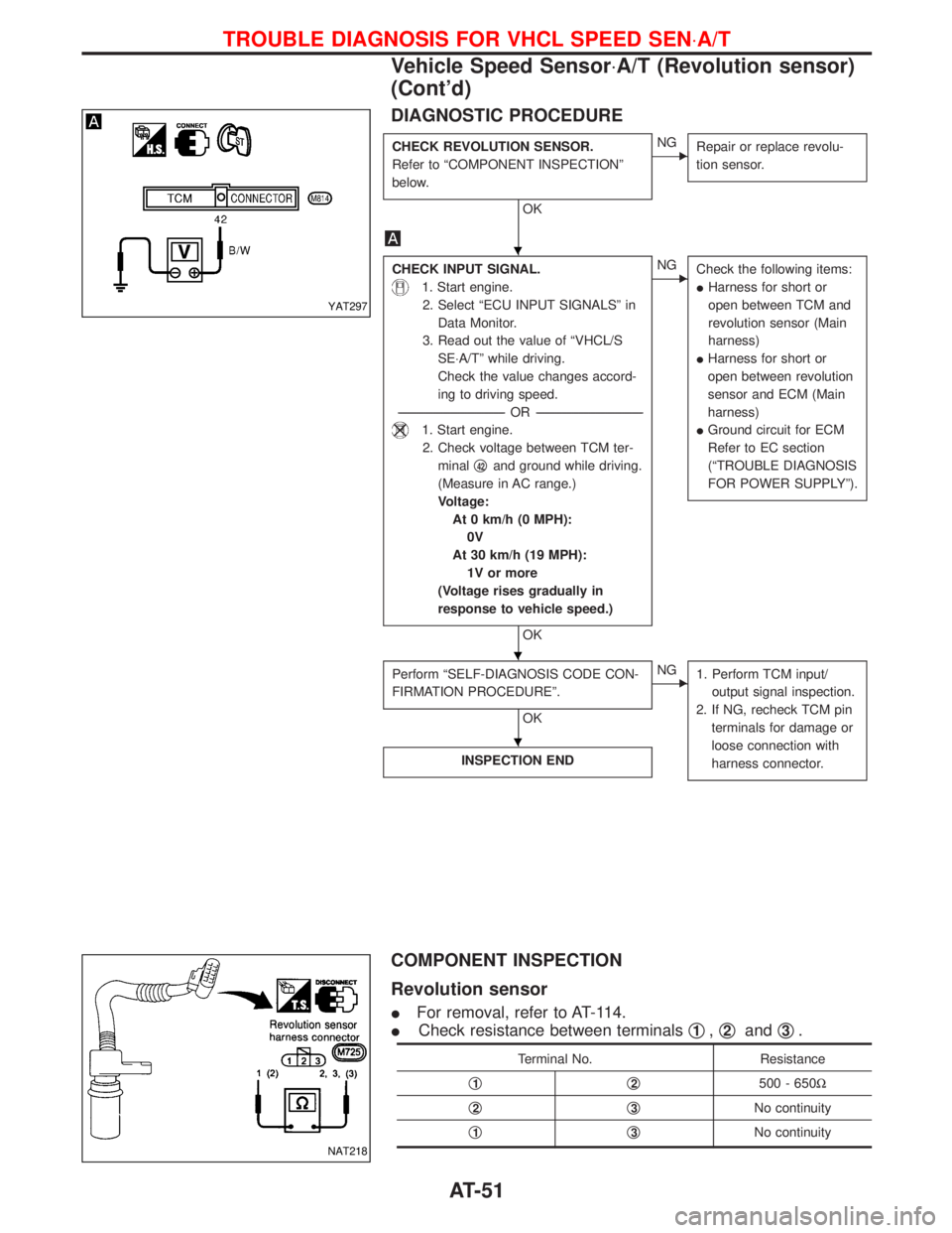
DIAGNOSTIC PROCEDURE
CHECK REVOLUTION SENSOR.
Refer to ªCOMPONENT INSPECTIONº
below.
OK
ENG
Repair or replace revolu-
tion sensor.
CHECK INPUT SIGNAL.
1. Start engine.
2. Select ªECU INPUT SIGNALSº in
Data Monitor.
3. Read out the value of ªVHCL/S
SE×A/Tº while driving.
Check the value changes accord-
ing to driving speed.
-----------------------------------------------------------------------------------------------------------------------OR -----------------------------------------------------------------------------------------------------------------------
1. Start engine.
2. Check voltage between TCM ter-
minalq
42and ground while driving.
(Measure in AC range.)
Voltage:
At 0 km/h (0 MPH):
0V
At 30 km/h (19 MPH):
1V or more
(Voltage rises gradually in
response to vehicle speed.)
OK
ENG
Check the following items:
IHarness for short or
open between TCM and
revolution sensor (Main
harness)
IHarness for short or
open between revolution
sensor and ECM (Main
harness)
IGround circuit for ECM
Refer to EC section
(ªTROUBLE DIAGNOSIS
FOR POWER SUPPLYº).
Perform ªSELF-DIAGNOSIS CODE CON-
FIRMATION PROCEDUREº.
OK
ENG
1. Perform TCM input/
output signal inspection.
2. If NG, recheck TCM pin
terminals for damage or
loose connection with
harness connector.
INSPECTION END
COMPONENT INSPECTION
Revolution sensor
IFor removal, refer to AT-114.
ICheck resistance between terminalsq
1,q2andq3.
Terminal No. Resistance
q
1q2500 - 650W
q
2q3No continuity
q
1q3No continuity
YAT297
NAT218
H
H
H
TROUBLE DIAGNOSIS FOR VHCL SPEED SEN×A/T
Vehicle Speed Sensor×A/T (Revolution sensor)
(Cont'd)
AT-51
Page 57 of 1767
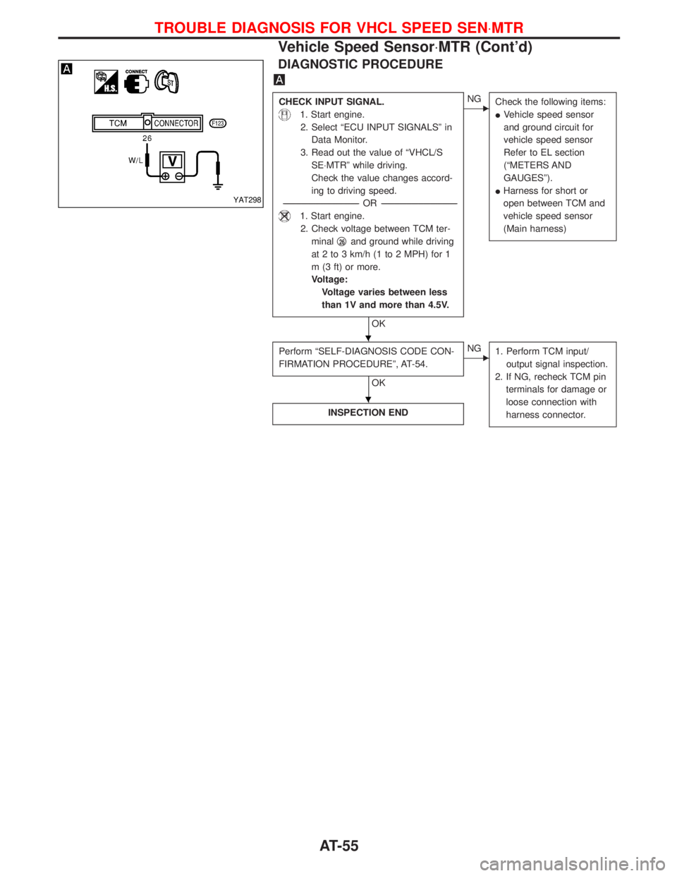
DIAGNOSTIC PROCEDURE
CHECK INPUT SIGNAL.
1. Start engine.
2. Select ªECU INPUT SIGNALSº in
Data Monitor.
3. Read out the value of ªVHCL/S
SE×MTRº while driving.
Check the value changes accord-
ing to driving speed.
-----------------------------------------------------------------------------------------------------------------------OR -----------------------------------------------------------------------------------------------------------------------
1. Start engine.
2. Check voltage between TCM ter-
minalq
26and ground while driving
at 2 to 3 km/h (1 to 2 MPH) for 1
m (3 ft) or more.
Voltage:
Voltage varies between less
than 1V and more than 4.5V.
OK
ENG
Check the following items:
IVehicle speed sensor
and ground circuit for
vehicle speed sensor
Refer to EL section
(ªMETERS AND
GAUGESº).
IHarness for short or
open between TCM and
vehicle speed sensor
(Main harness)
Perform ªSELF-DIAGNOSIS CODE CON-
FIRMATION PROCEDUREº, AT-54.
OK
ENG
1. Perform TCM input/
output signal inspection.
2. If NG, recheck TCM pin
terminals for damage or
loose connection with
harness connector.
INSPECTION END
YAT298
H
H
TROUBLE DIAGNOSIS FOR VHCL SPEED SEN×MTR
Vehicle Speed Sensor×MTR (Cont'd)
AT-55
Page 63 of 1767
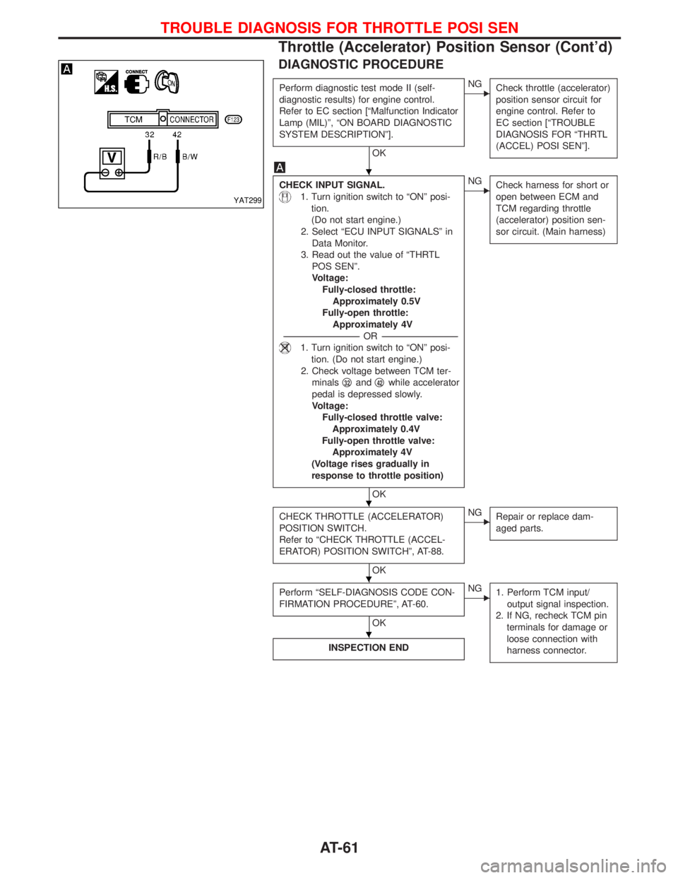
DIAGNOSTIC PROCEDURE
Perform diagnostic test mode II (self-
diagnostic results) for engine control.
Refer to EC section [ªMalfunction Indicator
Lamp (MIL)º, ªON BOARD DIAGNOSTIC
SYSTEM DESCRIPTIONº].
OK
ENG
Check throttle (accelerator)
position sensor circuit for
engine control. Refer to
EC section [ªTROUBLE
DIAGNOSIS FOR ªTHRTL
(ACCEL) POSI SENº].
CHECK INPUT SIGNAL.
1. Turn ignition switch to ªONº posi-
tion.
(Do not start engine.)
2. Select ªECU INPUT SIGNALSº in
Data Monitor.
3. Read out the value of ªTHRTL
POS SENº.
Voltage:
Fully-closed throttle:
Approximately 0.5V
Fully-open throttle:
Approximately 4V
-----------------------------------------------------------------------------------------------------------------------OR -----------------------------------------------------------------------------------------------------------------------
1. Turn ignition switch to ªONº posi-
tion. (Do not start engine.)
2. Check voltage between TCM ter-
minalsq
32andq42while accelerator
pedal is depressed slowly.
Voltage:
Fully-closed throttle valve:
Approximately 0.4V
Fully-open throttle valve:
Approximately 4V
(Voltage rises gradually in
response to throttle position)
OK
ENG
Check harness for short or
open between ECM and
TCM regarding throttle
(accelerator) position sen-
sor circuit. (Main harness)
CHECK THROTTLE (ACCELERATOR)
POSITION SWITCH.
Refer to ªCHECK THROTTLE (ACCEL-
ERATOR) POSITION SWITCHº, AT-88.
OK
ENG
Repair or replace dam-
aged parts.
Perform ªSELF-DIAGNOSIS CODE CON-
FIRMATION PROCEDUREº, AT-60.
OK
ENG
1. Perform TCM input/
output signal inspection.
2. If NG, recheck TCM pin
terminals for damage or
loose connection with
harness connector.
INSPECTION END
YAT299
H
H
H
H
TROUBLE DIAGNOSIS FOR THROTTLE POSI SEN
Throttle (Accelerator) Position Sensor (Cont'd)
AT-61
Page 80 of 1767
![NISSAN TERRANO 2002 Service Repair Manual qA
CHECK INPUT SIGNAL OF A/T FLUID
TEMPERATURE SENSOR.
1. Start engine.
2. Select ªECU INPUT SIGNALSº in
Data Monitor.
3. Read out the value of ªFLUID
TEMP SEº.
Voltage:
Cold [20ÉC (68ÉF)]®
Hot NISSAN TERRANO 2002 Service Repair Manual qA
CHECK INPUT SIGNAL OF A/T FLUID
TEMPERATURE SENSOR.
1. Start engine.
2. Select ªECU INPUT SIGNALSº in
Data Monitor.
3. Read out the value of ªFLUID
TEMP SEº.
Voltage:
Cold [20ÉC (68ÉF)]®
Hot](/img/5/57393/w960_57393-79.png)
qA
CHECK INPUT SIGNAL OF A/T FLUID
TEMPERATURE SENSOR.
1. Start engine.
2. Select ªECU INPUT SIGNALSº in
Data Monitor.
3. Read out the value of ªFLUID
TEMP SEº.
Voltage:
Cold [20ÉC (68ÉF)]®
Hot [80ÉC (176ÉF)]:
Approximately
1.5V®0.5V
-----------------------------------------------------------------------------------------------------------------------OR -----------------------------------------------------------------------------------------------------------------------
1. Start engine.
2. Check voltage between TCM ter-
minalq
47and ground while warm-
ing up A/T.
Voltage:
Cold [20ÉC (68ÉF)]®
Hot [80ÉC (176ÉF)]:
Approximately
1.5V®0.5V
OK
ENG
Check the following item:
IHarness for short or
open between TCM and
terminal cord assembly
(Main harness)
Perform ªSELF-DIAGNOSIS CODE CON-
FIRMATION PROCEDUREº, AT-76.
OK
ENG
1. Perform TCM input/
output signal inspection.
2. If NG, recheck TCM pin
terminals for damage or
loose connection with
harness connector.
INSPECTION END
COMPONENT INSPECTION
A/T fluid temperature sensor
IFor removal, refer to AT-113.
ICheck resistance between terminalsq
6andq7while changing
temperature as shown at left.
Temperature ÉC (ÉF) Resistance
20 (68) Approximately 2.5 kW
80 (176) Approximately 0.3 kW
YAT318
YAT319
H
H
H
TROUBLE DIAGNOSIS FOR BATT/FLUID TEMP SEN
A/T Fluid Temperature Sensor and TCM Power
Source (Cont'd)
AT-78
Page 83 of 1767
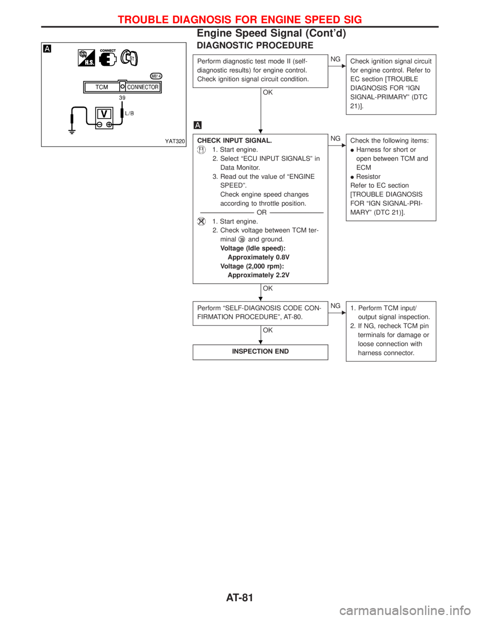
DIAGNOSTIC PROCEDURE
Perform diagnostic test mode II (self-
diagnostic results) for engine control.
Check ignition signal circuit condition.
OK
ENG
Check ignition signal circuit
for engine control. Refer to
EC section [TROUBLE
DIAGNOSIS FOR ªIGN
SIGNAL-PRIMARYº (DTC
21)].
CHECK INPUT SIGNAL.
1. Start engine.
2. Select ªECU INPUT SIGNALSº in
Data Monitor.
3. Read out the value of ªENGINE
SPEEDº.
Check engine speed changes
according to throttle position.
-----------------------------------------------------------------------------------------------------------------------OR -----------------------------------------------------------------------------------------------------------------------
1. Start engine.
2. Check voltage between TCM ter-
minalq
39and ground.
Voltage (Idle speed):
Approximately 0.8V
Voltage (2,000 rpm):
Approximately 2.2V
OK
ENG
Check the following items:
IHarness for short or
open between TCM and
ECM
IResistor
Refer to EC section
[TROUBLE DIAGNOSIS
FOR ªIGN SIGNAL-PRI-
MARYº (DTC 21)].
Perform ªSELF-DIAGNOSIS CODE CON-
FIRMATION PROCEDUREº, AT-80.
OK
ENG
1. Perform TCM input/
output signal inspection.
2. If NG, recheck TCM pin
terminals for damage or
loose connection with
harness connector.
INSPECTION END
YAT320
H
H
H
TROUBLE DIAGNOSIS FOR ENGINE SPEED SIG
Engine Speed Signal (Cont'd)
AT-81
Page 91 of 1767
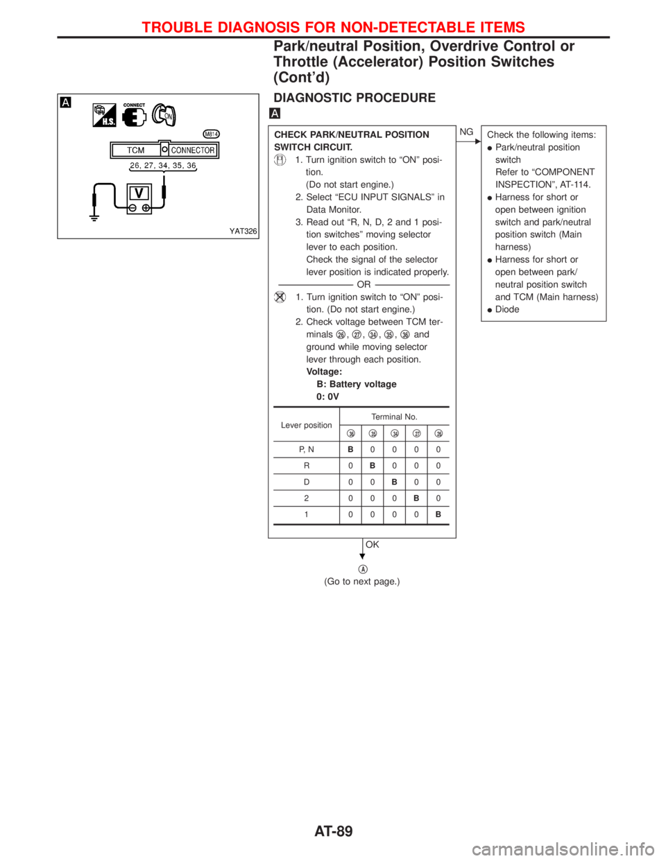
DIAGNOSTIC PROCEDURE
CHECK PARK/NEUTRAL POSITION
SWITCH CIRCUIT.
1. Turn ignition switch to ªONº posi-
tion.
(Do not start engine.)
2. Select ªECU INPUT SIGNALSº in
Data Monitor.
3. Read out ªR, N, D, 2 and 1 posi-
tion switchesº moving selector
lever to each position.
Check the signal of the selector
lever position is indicated properly.
-----------------------------------------------------------------------------------------------------------------------OR -----------------------------------------------------------------------------------------------------------------------
1. Turn ignition switch to ªONº posi-
tion. (Do not start engine.)
2. Check voltage between TCM ter-
minalsq
26,q27,q34,q35,q36and
ground while moving selector
lever through each position.
Voltage:
B: Battery voltage
0: 0V
OK
ENG
Check the following items:
IPark/neutral position
switch
Refer to ªCOMPONENT
INSPECTIONº, AT-114.
IHarness for short or
open between ignition
switch and park/neutral
position switch (Main
harness)
IHarness for short or
open between park/
neutral position switch
and TCM (Main harness)
IDiode
qA
(Go to next page.)
Lever positionTerminal No.
q36q35q34q27q26
P, NB0000
R0B000
D00B00
2 000B0
1 0000B
YAT326
H
TROUBLE DIAGNOSIS FOR NON-DETECTABLE ITEMS
Park/neutral Position, Overdrive Control or
Throttle (Accelerator) Position Switches
(Cont'd)
AT-89
Page 92 of 1767
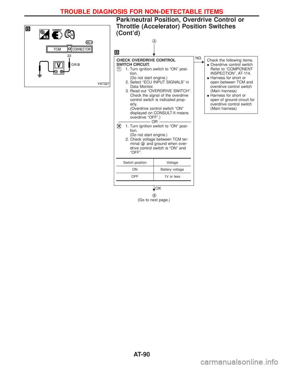
qA
CHECK OVERDRIVE CONTROL
SWITCH CIRCUIT.
1. Turn ignition switch to ªONº posi-
tion.
(Do not start engine.)
2. Select ªECU INPUT SIGNALSº in
Data Monitor.
3. Read out ªOVERDRIVE SWITCHº.
Check the signal of the overdrive
control switch is indicated prop-
erly.
(Overdrive control switch ªONº
displayed on CONSULT-II means
overdrive ªOFFº.)
-----------------------------------------------------------------------------------------------------------------------OR -----------------------------------------------------------------------------------------------------------------------
1. Turn ignition switch to ªONº posi-
tion.
(Do not start engine.)
2. Check voltage between TCM ter-
minalq
22and ground when over-
drive control switch is ªONº and
ªOFFº.
OK
ENG
Check the following items.
IOverdrive control switch
Refer to ªCOMPONENT
INSPECTIONº, AT-114.
IHarness for short or
open between TCM and
overdrive control switch
(Main harness)
IHarness for short or
open of ground circuit for
overdrive control switch
(Main harness)
qB(Go to next page.)
Switch position Voltage
ON Battery voltage
OFF 1V or less
YAT327
H
H
TROUBLE DIAGNOSIS FOR NON-DETECTABLE ITEMS
Park/neutral Position, Overdrive Control or
Throttle (Accelerator) Position Switches
(Cont'd)
AT-90
Page 93 of 1767
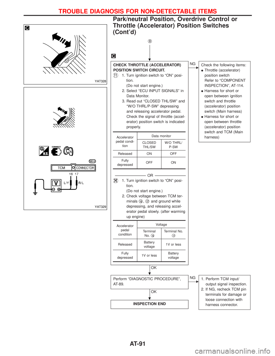
qB
CHECK THROTTLE (ACCELERATOR)
POSITION SWITCH CIRCUIT.
1. Turn ignition switch to ªONº posi-
tion.
(Do not start engine.)
2. Select ªECU INPUT SIGNALSº in
Data Monitor.
3. Read out ªCLOSED THL/SWº and
ªW/O THRL/P-SWº depressing
and releasing accelerator pedal.
Check the signal of throttle (accel-
erator) position switch is indicated
properly.
-----------------------------------------------------------------------------------------------------------------------OR -----------------------------------------------------------------------------------------------------------------------
1. Turn ignition switch to ªONº posi-
tion.
(Do not start engine.)
2. Check voltage between TCM ter-
minalsq
16,q17and ground while
depressing, and releasing accel-
erator pedal slowly. (after warming
up engine)
OK
ENG
Check the following items:
IThrottle (accelerator)
position switch
Refer to ªCOMPONENT
INSPECTIONº, AT-114.
IHarness for short or
open between ignition
switch and throttle
(accelerator) position
switch (Main harness)
IHarness for short or
open between throttle
(accelerator) position
switch and TCM (Main
harness)
Perform ªDIAGNOSTIC PROCEDUREº,
AT-89.
OK
ENG
1. Perform TCM input/
output signal inspection.
2. If NG, recheck TCM pin
terminals for damage or
loose connection with
harness connector.
INSPECTION END
Accelerator
pedal condi-
tionData monitor
CLOSED
THL/SWW/O THRL/
P-SW
Released ON OFF
Fully
depressedOFF ON
Accelerator
pedal
conditionVoltage
Terminal
No.q
16Terminal No.
q17
ReleasedBattery
voltage1V or less
Fully
depressed1V or lessBattery
voltage
YAT328
YAT329
H
H
H
TROUBLE DIAGNOSIS FOR NON-DETECTABLE ITEMS
Park/neutral Position, Overdrive Control or
Throttle (Accelerator) Position Switches
(Cont'd)
AT-91