Start NISSAN TERRANO 2002 Service Repair Manual
[x] Cancel search | Manufacturer: NISSAN, Model Year: 2002, Model line: TERRANO, Model: NISSAN TERRANO 2002Pages: 1767, PDF Size: 41.51 MB
Page 1 of 1767
Edition: February 2002
Release: February 2002 (01)
Publication No.: SM2E00-1R20E0E
GENERAL INFORMATIONGI
MAINTENANCEMA
ENGINE MECHANICALEM
ENGINE LUBRICATION &
COOLING SYSTEMSLC
ENGINE CONTROL SYSTEMEC
ACCELERATOR CONTROL,
FUEL & EXHAUST SYSTEMFE
CLUTCHCL
MANUAL TRANSMISSIONMT
AUTOMATIC TRANSMISSIONAT
TRANSFERTF
PROPELLER SHAFT &
DIFFERENTIAL CARRIERPD
FRONT AXLE & FRONT SUSPENSIONFA
REAR AXLE & REAR SUSPENSIONRA
BRAKE SYSTEMBR
STEERING SYSTEMST
RESTRAINT SYSTEMRS
BODY & TRIMBT
HEATER & AIR CONDITIONERHA
STARTING & CHARGING SYSTEMSSC
ELECTRICAL SYSTEMEL
ALPHABETICAL INDEXIDX
TERRANO
MODEL R20 SERIES
NISSAN EUROPE N.V.
NISSAN EUROPE N.V.
Produced in The Netherlands
QUICK REFERENCE INDEX
Page 2 of 1767
FOREWORD
This manual contains maintenance and repair procedures for NISSAN
TERRANO, model R20 series.
In order to assure your safety and the efficient functioning of the vehicle,
this manual should be read thoroughly. It is especially important that the
PRECAUTIONS in the GI section be completely understood before starting
any repair task.
All information in this manual is based on the latest product information
at the time of publication. The right is reserved to make changes in speci-
fications and methods at any time without notice.
IMPORTANT SAFETY NOTICE
The proper performance of service is essential for both the safety of the
technician and the efficient functioning of the vehicle.
The service methods in this Service Manual are described in such a man-
ner that the service may be performed safely and accurately.
Service varies with the procedures used, the skills of the technician and the
tools and parts available. Accordingly, anyone using service procedures,
tools or parts which are not specifically recommended by NISSAN must
first completely satisfy himself that neither his safety nor the vehicle's
safety will be jeopardized by the service method selected.
NISSAN EUROPE N.V.
Service Operations Section
Paris, France
Page 4 of 1767
1. SPORT Indicator Lamp Does Not Come On ........94
2. SPORT or SNOW Indicator Lamp Does Not
Come On...................................................................95
3. O/D OFF Indicator Lamp Does Not Come On......95
4. SPORT Indicator Lamp Does Not Come On ........96
5. Engine Cannot Be Started In²P²and²N²
Position......................................................................97
6. In²P²Position, Vehicle Moves Forward Or
Backward When Pushed...........................................97
7. In²N²Position, Vehicle Moves .............................98
8. Large Shock.²N²->²R²Position .........................99
9. Vehicle Does Not Creep Backward In²R²
Position....................................................................100
10. Vehicle Does Not Creep Forward In²D²,²2²
Or²1²Position.........................................................101
11. Vehicle Cannot Be Started From D
1.................102
12. A/T Does Not Shift: D
1-> D2Or Does Not
Kickdown: D
4-> D2..................................................103
13. A/T Does Not Shift: D
2-> D3............................104
14. A/T Does Not Shift: D
3-> D4.............................105
15. A/T Does Not Perform Lock-up .........................106
16. A/T Does Not Hold Lock-up Condition ..............107
17. Lock-up Is Not Released ...................................107
18. Engine Speed Does Not Return To Idle (Light
Braking D
4-> D3) .....................................................108
19. Vehicle Does Not Start From D
1.......................109
20. A/T Does Not Shift: D
2-> D1When
Depressing Accelerator Pedal................................. 110
21. A/T Does Not Shift: D
4-> D3, When
Overdrive Control Switch²ON²->²OFF²............... 111
22. A/T Does Not Shift: D
3-> 22, When Selector
Lever²D²->²2²Position......................................... 111
23. A/T Does Not Shift: 2
2-> 11, When Selector
Lever²2²->²1²Position ......................................... 112
24. Vehicle Does Not Decelerate By Engine
Brake........................................................................ 112
ON-VEHICLE SERVICE.............................................. 113Control Valve Assembly and Accumulators ............. 113
Revolution Sensor Replacement ............................. 114
Rear Oil Seal Replacement ..................................... 114
Parking Components Inspection.............................. 114
Park/neutral Position Switch Adjustment ................. 114
Manual Control Linkage Adjustment........................ 115
REMOVAL AND INSTALLATION................................ 116
Removal ................................................................... 116
Installation ................................................................ 117
MAJOR OVERHAUL................................................... 119
Oil Channel ..............................................................121
Locations of Needle Bearings, Thrust Washers
and Snap Rings .......................................................122
DISASSEMBLY............................................................123
Disassembly.............................................................123
REPAIR FOR COMPONENT PARTS..........................134
Oil Pump ..................................................................134
Control Valve Assembly ...........................................138
Control Valve Upper Body .......................................144
Control Valve Lower Body .......................................149
Reverse Clutch ........................................................151
High Clutch ..............................................................155
Forward and Overrun Clutches ...............................157
Low & Reverse Brake..............................................161
Forward Clutch Drum Assembly ..............................165
Rear Internal Gear and Forward Clutch Hub ..........168
Band Servo Piston Assembly ..................................171
Parking Pawl Components ......................................175
ASSEMBLY..................................................................177
Assembly (1) ............................................................177
Adjustment ...............................................................185
Assembly (2) ............................................................188
A/T FLUID COOLER SYSTEM...................................195
A/T Fluid Cooler.......................................................195
SERVICE DATA AND SPECIFICATIONS (SDS)........196
General Specifications .............................................196
Specifications and Adjustment.................................196
When you read wiring diagrams:
IRead GI section, ªHOW TO READ WIRING DIAGRAMSº.
ISee EL section, ªPOWER SUPPLY ROUTINGº for power distribution circuit.
When you perform trouble diagnoses, read GI section, ªHOW TO FOLLOW FLOW CHART IN
TROUBLE DIAGNOSESº and ªHOW TO PERFORM EFFICIENT DIAGNOSIS FOR AN ELECTRI-
CAL INCIDENTº.
CONTENTS(Cont'd)
AT- 2
Page 12 of 1767
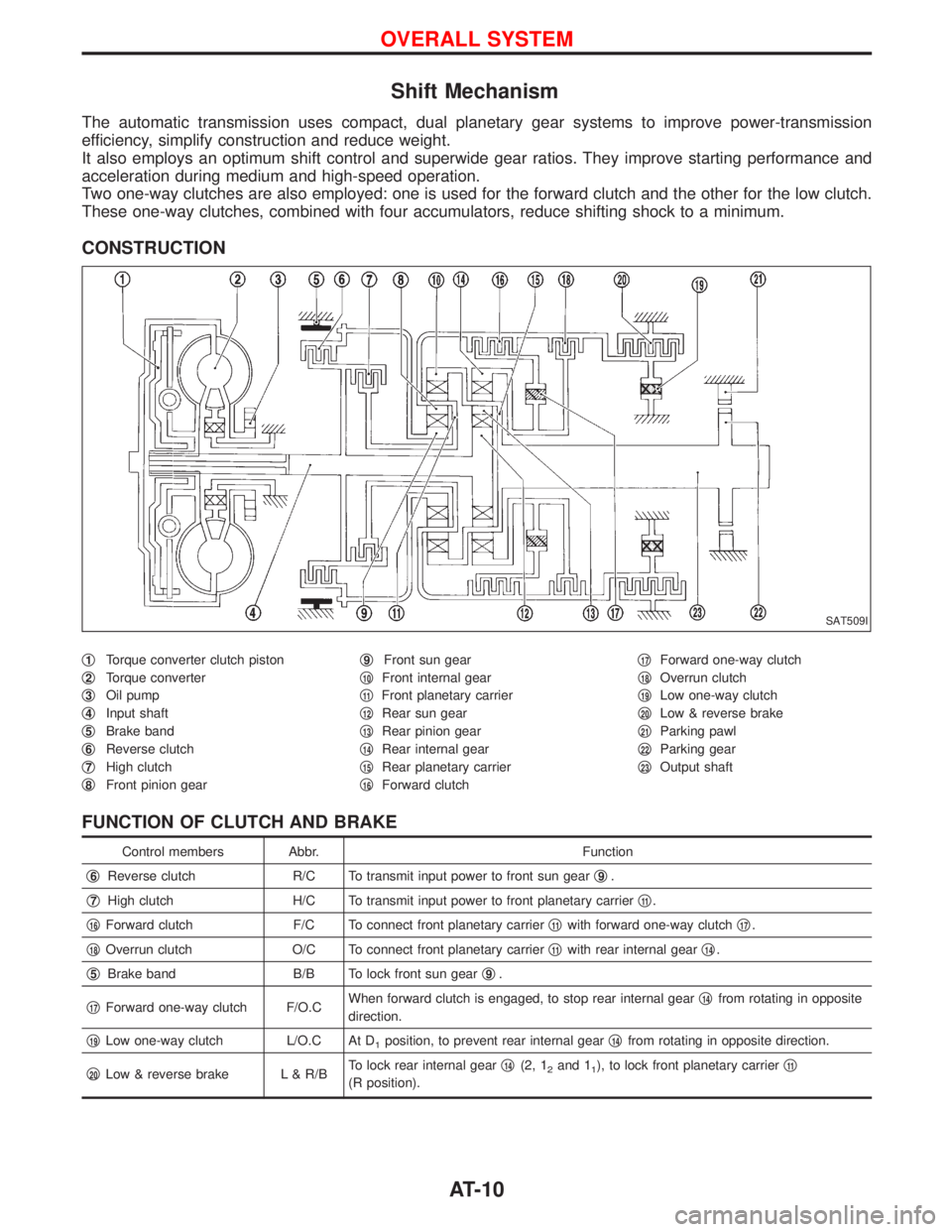
Shift Mechanism
The automatic transmission uses compact, dual planetary gear systems to improve power-transmission
efficiency, simplify construction and reduce weight.
It also employs an optimum shift control and superwide gear ratios. They improve starting performance and
acceleration during medium and high-speed operation.
Two one-way clutches are also employed: one is used for the forward clutch and the other for the low clutch.
These one-way clutches, combined with four accumulators, reduce shifting shock to a minimum.
CONSTRUCTION
q1Torque converter clutch piston
q
2Torque converter
q
3Oil pump
q
4Input shaft
q
5Brake band
q
6Reverse clutch
q
7High clutch
q
8Front pinion gearq
9Front sun gear
q
10Front internal gear
q
11Front planetary carrier
q
12Rear sun gear
q
13Rear pinion gear
q
14Rear internal gear
q
15Rear planetary carrier
q
16Forward clutchq
17Forward one-way clutch
q
18Overrun clutch
q
19Low one-way clutch
q
20Low & reverse brake
q
21Parking pawl
q
22Parking gear
q
23Output shaft
FUNCTION OF CLUTCH AND BRAKE
Control members Abbr. Function
q
6Reverse clutch R/C To transmit input power to front sun gearq9.
q
7High clutch H/C To transmit input power to front planetary carrierq11.
q
16Forward clutch F/C To connect front planetary carrierq11with forward one-way clutchq17.
q
18Overrun clutch O/C To connect front planetary carrierq11with rear internal gearq14.
q
5Brake band B/B To lock front sun gearq9.
q
17Forward one-way clutch F/O.CWhen forward clutch is engaged, to stop rear internal gearq14from rotating in opposite
direction.
q
19Low one-way clutch L/O.C At D1position, to prevent rear internal gearq14from rotating in opposite direction.
q
20Low & reverse brake L & R/BTo lock rear internal gearq14(2, 12and 11), to lock front planetary carrierq11
(R position).
SAT509I
OVERALL SYSTEM
AT-10
Page 16 of 1767
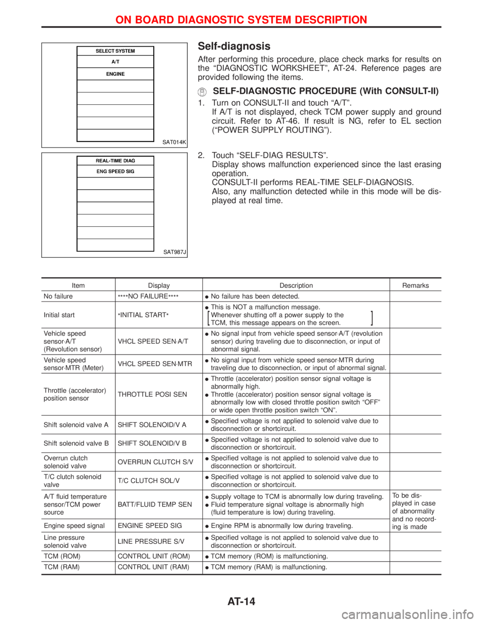
Self-diagnosis
After performing this procedure, place check marks for results on
the ªDIAGNOSTIC WORKSHEETº, AT-24. Reference pages are
provided following the items.
SELF-DIAGNOSTIC PROCEDURE (With CONSULT-II)
1. Turn on CONSULT-II and touch ªA/Tº.
If A/T is not displayed, check TCM power supply and ground
circuit. Refer to AT-46. If result is NG, refer to EL section
(ªPOWER SUPPLY ROUTINGº).
2. Touch ªSELF-DIAG RESULTSº.
Display shows malfunction experienced since the last erasing
operation.
CONSULT-II performs REAL-TIME SELF-DIAGNOSIS.
Also, any malfunction detected while in this mode will be dis-
played at real time.
Item Display Description Remarks
No failure
****NO FAILURE
****INo failure has been detected.
Initial start
*INITIAL START
*IThis is NOT a malfunction message.
Whenever shutting off a power supply to the
TCM, this message appears on the screen.
[]
Vehicle speed
sensor×A/T
(Revolution sensor)VHCL SPEED SEN×A/TINo signal input from vehicle speed sensor×A/T (revolution
sensor) during traveling due to disconnection, or input of
abnormal signal.
Vehicle speed
sensor×MTR (Meter)VHCL SPEED SEN×MTRINo signal input from vehicle speed sensor×MTR during
traveling due to disconnection, or input of abnormal signal.
Throttle (accelerator)
position sensorTHROTTLE POSI SENIThrottle (accelerator) position sensor signal voltage is
abnormally high.
IThrottle (accelerator) position sensor signal voltage is
abnormally low with closed throttle position switch ªOFFº
or wide open throttle position switch ªONº.
Shift solenoid valve A SHIFT SOLENOID/V AISpecified voltage is not applied to solenoid valve due to
disconnection or shortcircuit.
Shift solenoid valve B SHIFT SOLENOID/V BISpecified voltage is not applied to solenoid valve due to
disconnection or shortcircuit.
Overrun clutch
solenoid valveOVERRUN CLUTCH S/VISpecified voltage is not applied to solenoid valve due to
disconnection or shortcircuit.
T/C clutch solenoid
valveT/C CLUTCH SOL/VISpecified voltage is not applied to solenoid valve due to
disconnection or shortcircuit.
A/T fluid temperature
sensor/TCM power
sourceBATT/FLUID TEMP SENISupply voltage to TCM is abnormally low during traveling.
IFluid temperature signal voltage is abnormally high
(fluid temperature is low) during traveling.To be dis-
played in case
of abnormality
and no record-
ing is made Engine speed signal ENGINE SPEED SIGIEngine RPM is abnormally low during traveling.
Line pressure
solenoid valveLINE PRESSURE S/VISpecified voltage is not applied to solenoid valve due to
disconnection or shortcircuit.
TCM (ROM) CONTROL UNIT (ROM)ITCM memory (ROM) is malfunctioning.
TCM (RAM) CONTROL UNIT (RAM)ITCM memory (RAM) is malfunctioning.
SAT014K
SAT987J
ON BOARD DIAGNOSTIC SYSTEM DESCRIPTION
AT-14
Page 17 of 1767
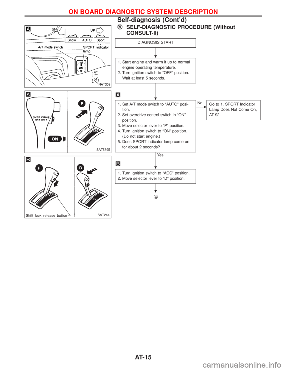
SELF-DIAGNOSTIC PROCEDURE (Without
CONSULT-II)
DIAGNOSIS START
1. Start engine and warm it up to normal
engine operating temperature.
2. Turn ignition switch to ªOFFº position.
Wait at least 5 seconds.
1. Set A/T mode switch to ªAUTOº posi-
tion.
2. Set overdrive control switch in ªONº
position.
3. Move selector lever to ªPº position.
4. Turn ignition switch to ªONº position.
(Do not start engine.)
5. Does SPORT indicator lamp come on
for about 2 seconds?
Ye s
ENo
Go to 1. SPORT Indicator
Lamp Does Not Come On,
AT-92.
1. Turn ignition switch to ªACCº position.
2. Move selector lever to ªDº position.
qA
NAT309
SAT879E
SAT244I
H
H
H
H
ON BOARD DIAGNOSTIC SYSTEM DESCRIPTION
Self-diagnosis (Cont'd)
AT-15
Page 18 of 1767
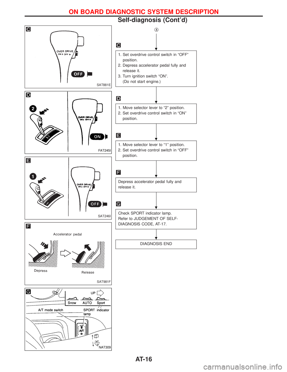
qA
1. Set overdrive control switch in ªOFFº
position.
2. Depress accelerator pedal fully and
release it.
3. Turn ignition switch ªONº.
(Do not start engine.)
1. Move selector lever to ª2º position.
2. Set overdrive control switch in ªONº
position.
1. Move selector lever to ª1º position.
2. Set overdrive control switch in ªOFFº
position.
Depress accelerator pedal fully and
release it.
Check SPORT indicator lamp.
Refer to JUDGEMENT OF SELF-
DIAGNOSIS CODE, AT-17.
DIAGNOSIS END
SAT881E
FAT245I
SAT246I
SAT981F
NAT309
H
H
H
H
H
H
ON BOARD DIAGNOSTIC SYSTEM DESCRIPTION
Self-diagnosis (Cont'd)
AT-16
Page 22 of 1767
Diagnosis by CONSULT-II
NOTICE
1. The CONSULT-II electrically displays shift timing and lock-up timing (that is, operation timing of each
solenoid).
Check for time difference between actual shift timing and the CONSULT-II display. If the difference is
noticeable, mechanical parts (except solenoids, sensors, etc.) may be malfunctioning. Check mechanical
parts using applicable diagnostic procedures.
2. Shift schedule (which implies gear position) displayed on CONSULT-II and that indicated in Service Manual
may differ slightly. This occurs because of the following reasons:
IActual shift schedule has more or less tolerance or allowance,
IShift schedule indicated in Service Manual refers to the point where shifts start. Gear position displayed
on CONSULT-II indicates the point where shifts are completed.
3. Shift solenoid valve ªAº or ªBº is displayed on CONSULT-II at the start of shifting. Gear position is displayed
upon completion of shifting (which is computed by TCM).
4. Additional CONSULT-II information can be found in the Operation Manual supplied with the CONSULT-II
unit.
SELF-DIAGNOSTIC RESULT TEST MODE
Refer to AT-14.
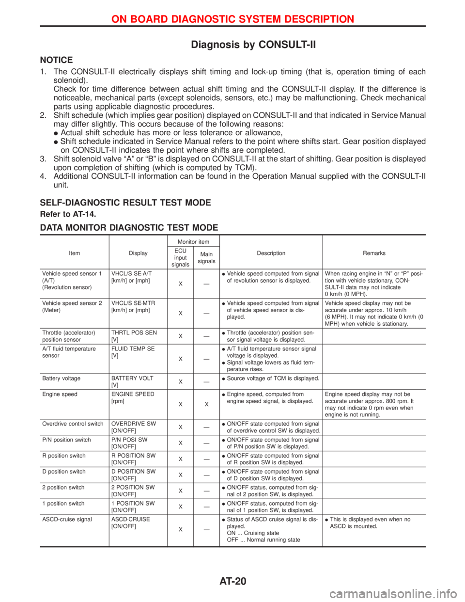
DATA MONITOR DIAGNOSTIC TEST MODE
Item DisplayMonitor item
Description Remarks ECU
input
signalsMain
signals
Vehicle speed sensor 1
(A/T)
(Revolution sensor)VHCL/S SE×A/T
[km/h] or [mph]
XÐIVehicle speed computed from signal
of revolution sensor is displayed.When racing engine in ªNº or ªPº posi-
tion with vehicle stationary, CON-
SULT-II data may not indicate
0 km/h (0 MPH).
Vehicle speed sensor 2
(Meter)VHCL/S SE×MTR
[km/h] or [mph]
XÐIVehicle speed computed from signal
of vehicle speed sensor is dis-
played.Vehicle speed display may not be
accurate under approx. 10 km/h
(6 MPH). It may not indicate 0 km/h (0
MPH) when vehicle is stationary.
Throttle (accelerator)
position sensorTHRTL POS SEN
[V]XÐIThrottle (accelerator) position sen-
sor signal voltage is displayed.
A/T fluid temperature
sensorFLUID TEMP SE
[V]
XÐIA/T fluid temperature sensor signal
voltage is displayed.
ISignal voltage lowers as fluid tem-
perature rises.
Battery voltage BATTERY VOLT
[V]XÐISource voltage of TCM is displayed.
Engine speed ENGINE SPEED
[rpm]
XXIEngine speed, computed from
engine speed signal, is displayed.Engine speed display may not be
accurate under approx. 800 rpm. It
may not indicate 0 rpm even when
engine is not running.
Overdrive control switch OVERDRIVE SW
[ON/OFF]XÐION/OFF state computed from signal
of overdrive control SW is displayed.
P/N position switch P/N POSI SW
[ON/OFF]XÐION/OFF state computed from signal
of P/N position SW is displayed.
R position switch R POSITION SW
[ON/OFF]XÐION/OFF state computed from signal
of R position SW is displayed.
D position switch D POSITION SW
[ON/OFF]XÐION/OFF state computed from signal
of D position SW is displayed.
2 position switch 2 POSITION SW
[ON/OFF]XÐION/OFF status, computed from sig-
nal of 2 position SW, is displayed.
1 position switch 1 POSITION SW
[ON/OFF]XÐION/OFF status, computed from sig-
nal of 1 position SW, is displayed.
ASCD-cruise signal ASCD×CRUISE
[ON/OFF]
XÐIStatus of ASCD cruise signal is dis-
played.
ON ... Cruising state
OFF ... Normal running stateIThis is displayed even when no
ASCD is mounted.
ON BOARD DIAGNOSTIC SYSTEM DESCRIPTION
AT-20
Page 24 of 1767
Introduction
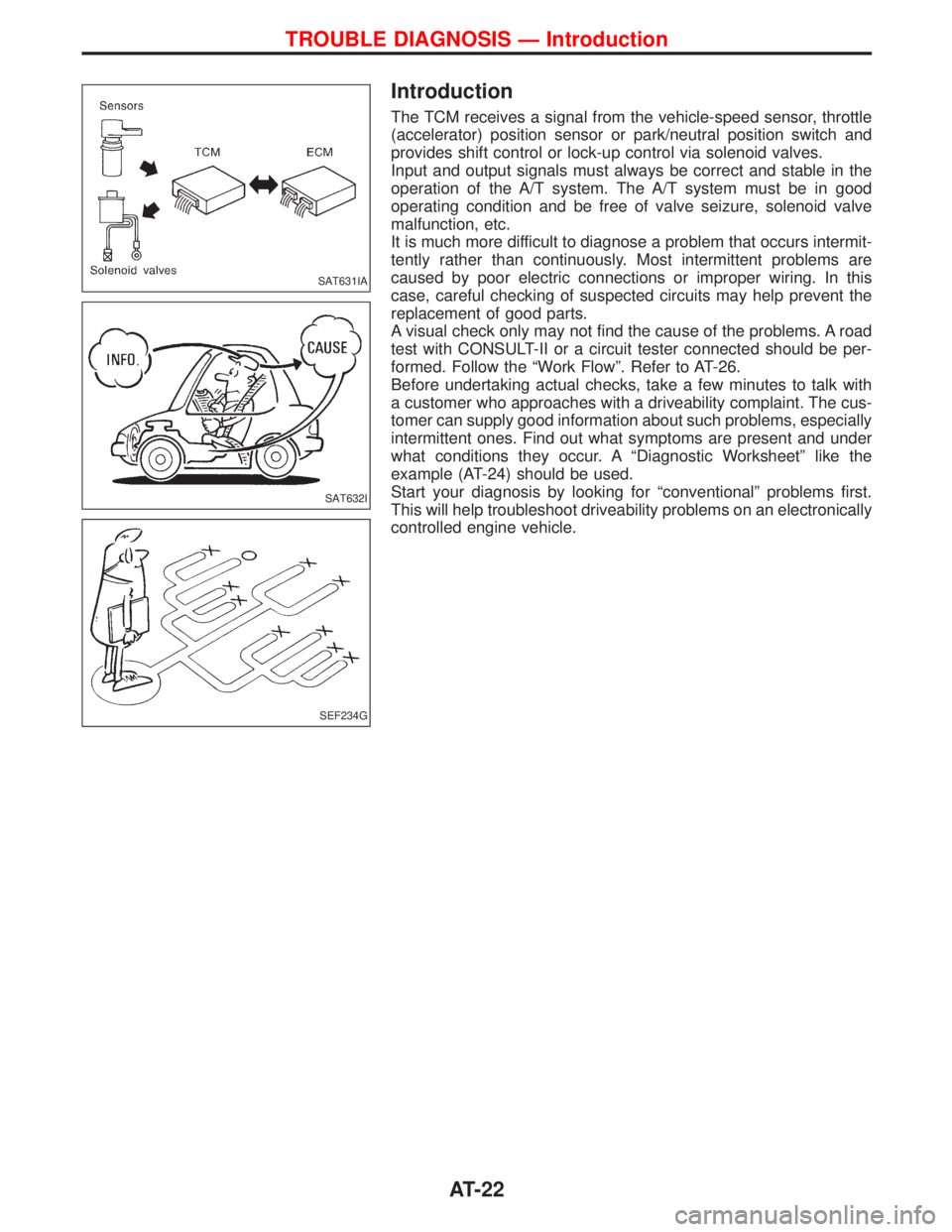
The TCM receives a signal from the vehicle-speed sensor, throttle
(accelerator) position sensor or park/neutral position switch and
provides shift control or lock-up control via solenoid valves.
Input and output signals must always be correct and stable in the
operation of the A/T system. The A/T system must be in good
operating condition and be free of valve seizure, solenoid valve
malfunction, etc.
It is much more difficult to diagnose a problem that occurs intermit-
tently rather than continuously. Most intermittent problems are
caused by poor electric connections or improper wiring. In this
case, careful checking of suspected circuits may help prevent the
replacement of good parts.
A visual check only may not find the cause of the problems. A road
test with CONSULT-II or a circuit tester connected should be per-
formed. Follow the ªWork Flowº. Refer to AT-26.
Before undertaking actual checks, take a few minutes to talk with
a customer who approaches with a driveability complaint. The cus-
tomer can supply good information about such problems, especially
intermittent ones. Find out what symptoms are present and under
what conditions they occur. A ªDiagnostic Worksheetº like the
example (AT-24) should be used.
Start your diagnosis by looking for ªconventionalº problems first.
This will help troubleshoot driveability problems on an electronically
controlled engine vehicle.
SAT631IA
SAT632I
SEF234G
TROUBLE DIAGNOSIS Ð Introduction
AT-22
Page 26 of 1767
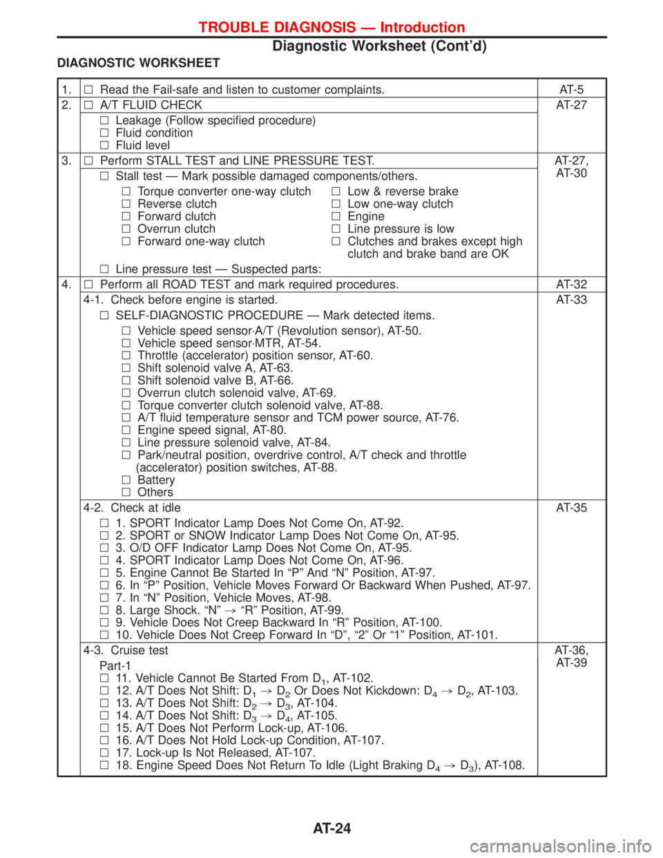
DIAGNOSTIC WORKSHEET
1.lRead the Fail-safe and listen to customer complaints. AT-5
2.lA/T FLUID CHECK AT-27
lLeakage (Follow specified procedure)
lFluid condition
lFluid level
3.lPerform STALL TEST and LINE PRESSURE TEST. AT-27,
AT-30
lStall test Ð Mark possible damaged components/others.
lTorque converter one-way clutch
lReverse clutch
lForward clutch
lOverrun clutch
lForward one-way clutchlLow & reverse brake
lLow one-way clutch
lEngine
lLine pressure is low
lClutches and brakes except high
clutch and brake band are OK
lLine pressure test Ð Suspected parts:
4.lPerform all ROAD TEST and mark required procedures. AT-32
4-1. Check before engine is started. AT-33
lSELF-DIAGNOSTIC PROCEDURE Ð Mark detected items.
lVehicle speed sensor×A/T (Revolution sensor), AT-50.
lVehicle speed sensor×MTR, AT-54.
lThrottle (accelerator) position sensor, AT-60.
lShift solenoid valve A, AT-63.
lShift solenoid valve B, AT-66.
lOverrun clutch solenoid valve, AT-69.
lTorque converter clutch solenoid valve, AT-88.
lA/T fluid temperature sensor and TCM power source, AT-76.
lEngine speed signal, AT-80.
lLine pressure solenoid valve, AT-84.
lPark/neutral position, overdrive control, A/T check and throttle
(accelerator) position switches, AT-88.
lBattery
lOthers
4-2. Check at idle AT-35
l1. SPORT Indicator Lamp Does Not Come On, AT-92.
l2. SPORT or SNOW Indicator Lamp Does Not Come On, AT-95.
l3. O/D OFF Indicator Lamp Does Not Come On, AT-95.
l4. SPORT Indicator Lamp Does Not Come On, AT-96.
l5. Engine Cannot Be Started In ªPº And ªNº Position, AT-97.
l6. In ªPº Position, Vehicle Moves Forward Or Backward When Pushed, AT-97.
l7. In ªNº Position, Vehicle Moves, AT-98.
l8. Large Shock. ªNº,ªRº Position, AT-99.
l9. Vehicle Does Not Creep Backward In ªRº Position, AT-100.
l10. Vehicle Does Not Creep Forward In ªDº, ª2º Or ª1º Position, AT-101.
4-3. Cruise testAT-36,
AT-39
Part-1
l11. Vehicle Cannot Be Started From D
1, AT-102.
l12. A/T Does Not Shift: D
1,D2Or Does Not Kickdown: D4,D2, AT-103.
l13. A/T Does Not Shift: D
2,D3, AT-104.
l14. A/T Does Not Shift: D
3,D4, AT-105.
l15. A/T Does Not Perform Lock-up, AT-106.
l16. A/T Does Not Hold Lock-up Condition, AT-107.
l17. Lock-up Is Not Released, AT-107.
l18. Engine Speed Does Not Return To Idle (Light Braking D
4,D3), AT-108.
TROUBLE DIAGNOSIS Ð Introduction
Diagnostic Worksheet (Cont'd)
AT-24