hood release NISSAN TERRANO 2002 Service Repair Manual
[x] Cancel search | Manufacturer: NISSAN, Model Year: 2002, Model line: TERRANO, Model: NISSAN TERRANO 2002Pages: 1767, PDF Size: 41.51 MB
Page 995 of 1767
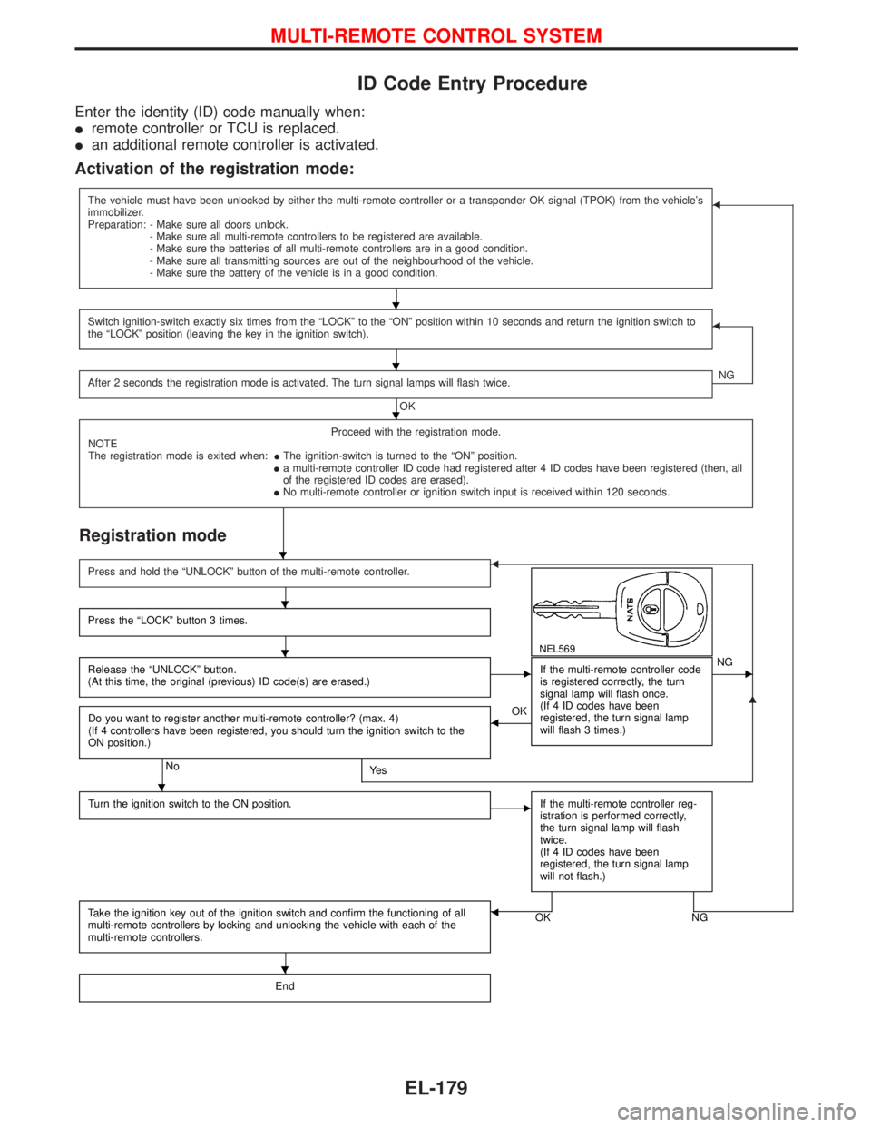
ID Code Entry Procedure
Enter the identity (ID) code manually when:
Iremote controller or TCU is replaced.
Ian additional remote controller is activated.
Activation of the registration mode:
The vehicle must have been unlocked by either the multi-remote controller or a transponder OK signal (TPOK) from the vehicle's
immobilizer.
Preparation: - Make sure all doors unlock.
- Make sure all multi-remote controllers to be registered are available.
- Make sure the batteries of all multi-remote controllers are in a good condition.
- Make sure all transmitting sources are out of the neighbourhood of the vehicle.
- Make sure the battery of the vehicle is in a good condition.F
Switch ignition-switch exactly six times from the ªLOCKº to the ªONº position within 10 seconds and return the ignition switch to
the ªLOCKº position (leaving the key in the ignition switch).F
After 2 seconds the registration mode is activated. The turn signal lamps will flash twice.
OKNG
Proceed with the registration mode.
NOTE
The registration mode is exited when:IThe ignition-switch is turned to the ªONº position.
Ia multi-remote controller ID code had registered after 4 ID codes have been registered (then, all
of the registered ID codes are erased).
INo multi-remote controller or ignition switch input is received within 120 seconds.
Registration mode
G
Press and hold the ªUNLOCKº button of the multi-remote controller.F
NEL569
Press the ªLOCKº button 3 times.
Release the ªUNLOCKº button.
(At this time, the original (previous) ID code(s) are erased.)EIf the multi-remote controller code
is registered correctly, the turn
signal lamp will flash once.
(If 4 ID codes have been
registered, the turn signal lamp
will flash 3 times.)ENG
Do you want to register another multi-remote controller? (max. 4)
(If 4 controllers have been registered, you should turn the ignition switch to the
ON position.)
NoYe s
FOK
Turn the ignition switch to the ON position.
EIf the multi-remote controller reg-
istration is performed correctly,
the turn signal lamp will flash
twice.
(If 4 ID codes have been
registered, the turn signal lamp
will not flash.)
Take the ignition key out of the ignition switch and confirm the functioning of all
multi-remote controllers by locking and unlocking the vehicle with each of the
multi-remote controllers.OK NGF
End
H
H
H
H
H
H
H
H
MULTI-REMOTE CONTROL SYSTEM
EL-179
Page 999 of 1767
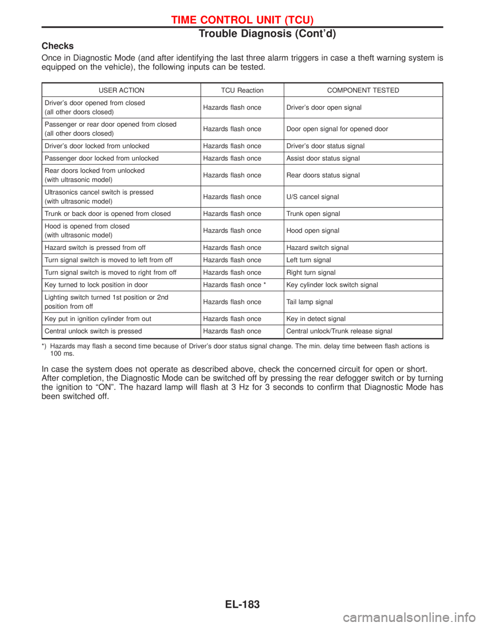
Checks
Once in Diagnostic Mode (and after identifying the last three alarm triggers in case a theft warning system is
equipped on the vehicle), the following inputs can be tested.
USER ACTION TCU Reaction COMPONENT TESTED
Driver's door opened from closed
(all other doors closed)Hazards flash once Driver's door open signal
Passenger or rear door opened from closed
(all other doors closed)Hazards flash once Door open signal for opened door
Driver's door locked from unlocked Hazards flash once Driver's door status signal
Passenger door locked from unlocked Hazards flash once Assist door status signal
Rear doors locked from unlocked
(with ultrasonic model)Hazards flash once Rear doors status signal
Ultrasonics cancel switch is pressed
(with ultrasonic model)Hazards flash once U/S cancel signal
Trunk or back door is opened from closed Hazards flash once Trunk open signal
Hood is opened from closed
(with ultrasonic model)Hazards flash once Hood open signal
Hazard switch is pressed from off Hazards flash once Hazard switch signal
Turn signal switch is moved to left from off Hazards flash once Left turn signal
Turn signal switch is moved to right from off Hazards flash once Right turn signal
Key turned to lock position in door Hazards flash once * Key cylinder lock switch signal
Lighting switch turned 1st position or 2nd
position from offHazards flash once Tail lamp signal
Key put in ignition cylinder from out Hazards flash once Key in detect signal
Central unlock switch is pressed Hazards flash once Central unlock/Trunk release signal
*) Hazards may flash a second time because of Driver's door status signal change. The min. delay time between flash actions is
100 ms.
In case the system does not operate as described above, check the concerned circuit for open or short.
After completion, the Diagnostic Mode can be switched off by pressing the rear defogger switch or by turning
the ignition to ªONº. The hazard lamp will flash at 3 Hz for 3 seconds to confirm that Diagnostic Mode has
been switched off.
TIME CONTROL UNIT (TCU)
Trouble Diagnosis (Cont'd)
EL-183
Page 1051 of 1767
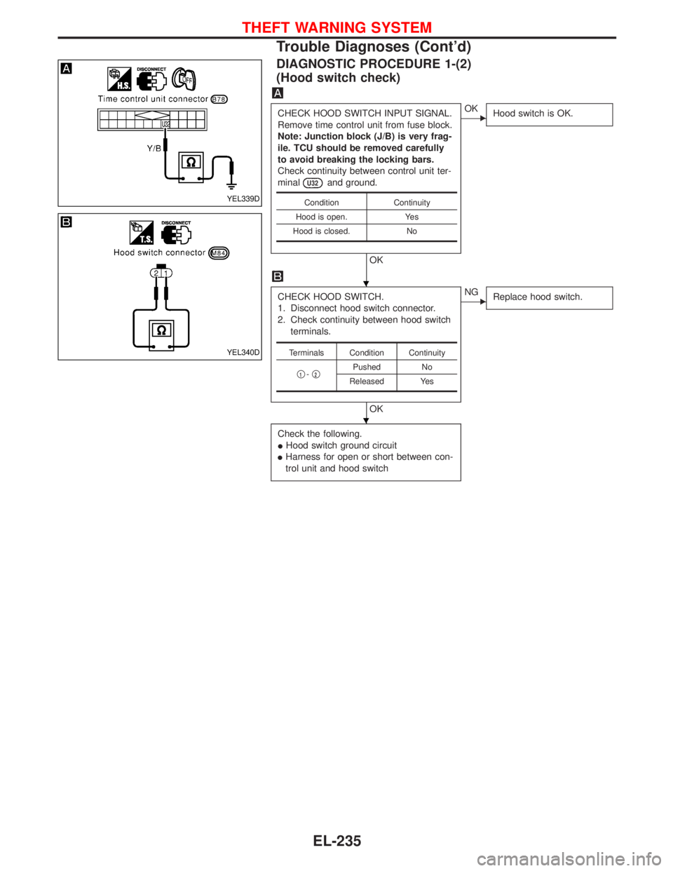
DIAGNOSTIC PROCEDURE 1-(2)
(Hood switch check)
CHECK HOOD SWITCH INPUT SIGNAL.
Remove time control unit from fuse block.
Note: Junction block (J/B) is very frag-
ile. TCU should be removed carefully
to avoid breaking the locking bars.
Check continuity between control unit ter-
minal
U32and ground.
OK
EOK
Hood switch is OK.
CHECK HOOD SWITCH.
1. Disconnect hood switch connector.
2. Check continuity between hood switch
terminals.
OK
ENG
Replace hood switch.
Check the following.
IHood switch ground circuit
IHarness for open or short between con-
trol unit and hood switch
Condition Continuity
Hood is open. Yes
Hood is closed. No
Terminals Condition Continuity
q
1-q2Pushed No
Released Yes
YEL339D
YEL340D
H
H
THEFT WARNING SYSTEM
Trouble Diagnoses (Cont'd)
EL-235
Page 1330 of 1767
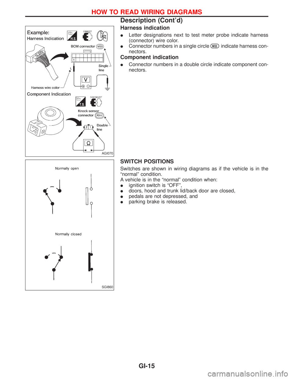
Harness indication
ILetter designations next to test meter probe indicate harness
(connector) wire color.
IConnector numbers in a single circle
M33indicate harness con-
nectors.
Component indication
IConnector numbers in a double circle indicate component con-
nectors.
SWITCH POSITIONS
Switches are shown in wiring diagrams as if the vehicle is in the
ªnormalº condition.
A vehicle is in the ªnormalº condition when:
Iignition switch is ªOFFº,
Idoors, hood and trunk lid/back door are closed,
Ipedals are not depressed, and
Iparking brake is released.
AGI070
SGI860
HOW TO READ WIRING DIAGRAMS
Description (Cont'd)
GI-15
Page 1463 of 1767
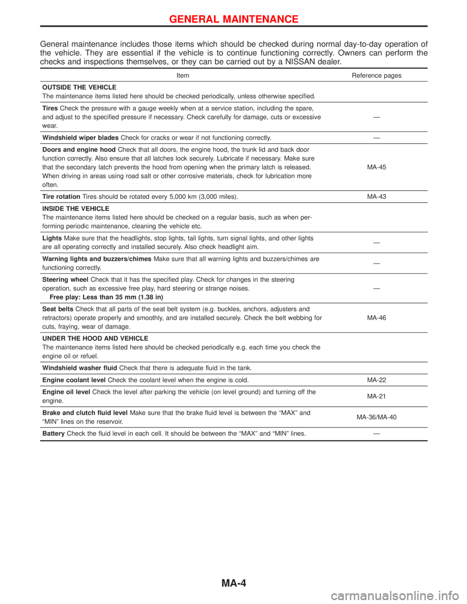
General maintenance includes those items which should be checked during normal day-to-day operation of
the vehicle. They are essential if the vehicle is to continue functioning correctly. Owners can perform the
checks and inspections themselves, or they can be carried out by a NISSAN dealer.
Item Reference pages
OUTSIDE THE VEHICLE
The maintenance items listed here should be checked periodically, unless otherwise specified.
TiresCheck the pressure with a gauge weekly when at a service station, including the spare,
and adjust to the specified pressure if necessary. Check carefully for damage, cuts or excessive
wear.Ð
Windshield wiper bladesCheck for cracks or wear if not functioning correctly. Ð
Doors and engine hoodCheck that all doors, the engine hood, the trunk lid and back door
function correctly. Also ensure that all latches lock securely. Lubricate if necessary. Make sure
that the secondary latch prevents the hood from opening when the primary latch is released.
When driving in areas using road salt or other corrosive materials, check for lubrication more
often.MA-45
Tire rotationTires should be rotated every 5,000 km (3,000 miles). MA-43
INSIDE THE VEHICLE
The maintenance items listed here should be checked on a regular basis, such as when per-
forming periodic maintenance, cleaning the vehicle etc.
LightsMake sure that the headlights, stop lights, tail lights, turn signal lights, and other lights
are all operating correctly and installed securely. Also check headlight aim.Ð
Warning lights and buzzers/chimesMake sure that all warning lights and buzzers/chimes are
functioning correctly.Ð
Steering wheelCheck that it has the specified play. Check for changes in the steering
operation, such as excessive free play, hard steering or strange noises.
Free play: Less than 35 mm (1.38 in)Ð
Seat beltsCheck that all parts of the seat belt system (e.g. buckles, anchors, adjusters and
retractors) operate properly and smoothly, and are installed securely. Check the belt webbing for
cuts, fraying, wear of damage.MA-46
UNDER THE HOOD AND VEHICLE
The maintenance items listed here should be checked periodically e.g. each time you check the
engine oil or refuel.
Windshield washer fluidCheck that there is adequate fluid in the tank.
Engine coolant levelCheck the coolant level when the engine is cold. MA-22
Engine oil levelCheck the level after parking the vehicle (on level ground) and turning off the
engine.MA-21
Brake and clutch fluid levelMake sure that the brake fluid level is between the ªMAXº and
ªMINº lines on the reservoir.MA-36/MA-40
BatteryCheck the fluid level in each cell. It should be between the ªMAXº and ªMINº lines. Ð
GENERAL MAINTENANCE
MA-4