coolant reservoir NISSAN TERRANO 2002 Service Repair Manual
[x] Cancel search | Manufacturer: NISSAN, Model Year: 2002, Model line: TERRANO, Model: NISSAN TERRANO 2002Pages: 1767, PDF Size: 41.51 MB
Page 473 of 1767
Overall Function Check
Use this procedure to check the overall function of the cooling fan.
During this check, a DTC might not be confirmed.
WARNING:
Never remove the radiator cap when the engine is hot. Serious
burns could be caused by high pressure fluid escaping from
the radiator.
Wrap a thick cloth around the cap. Carefully remove the cap
by turning it a quarter turn to allow built-up pressure to
escape. Then turn the cap all the way off.
WITH CONSULT-II
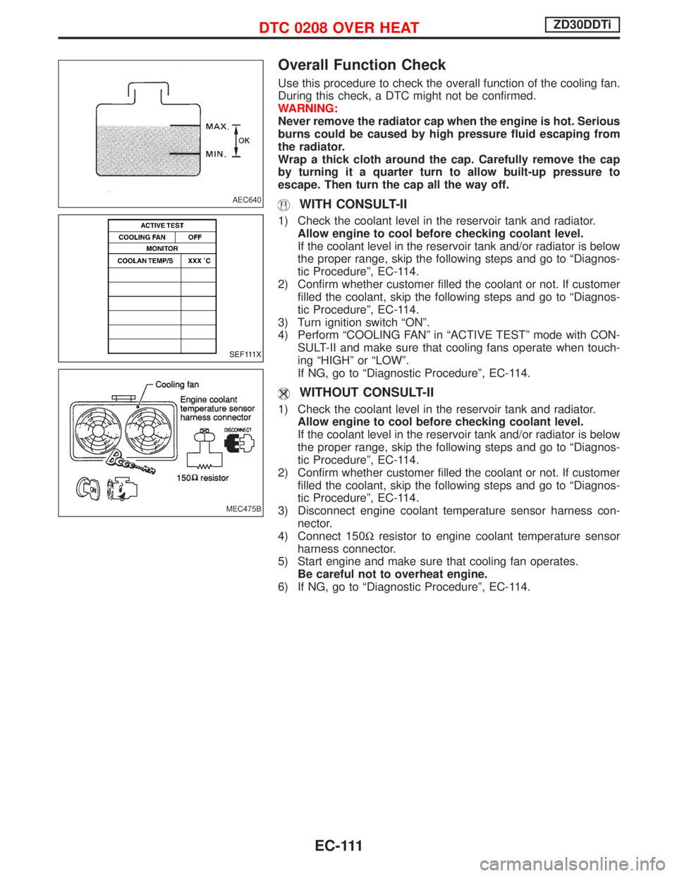
1) Check the coolant level in the reservoir tank and radiator.
Allow engine to cool before checking coolant level.
If the coolant level in the reservoir tank and/or radiator is below
the proper range, skip the following steps and go to ªDiagnos-
tic Procedureº, EC-114.
2) Confirm whether customer filled the coolant or not. If customer
filled the coolant, skip the following steps and go to ªDiagnos-
tic Procedureº, EC-114.
3) Turn ignition switch ªONº.
4) Perform ªCOOLING FANº in ªACTIVE TESTº mode with CON-
SULT-II and make sure that cooling fans operate when touch-
ing ªHIGHº or ªLOWº.
If NG, go to ªDiagnostic Procedureº, EC-114.
WITHOUT CONSULT-II
1) Check the coolant level in the reservoir tank and radiator.
Allow engine to cool before checking coolant level.
If the coolant level in the reservoir tank and/or radiator is below
the proper range, skip the following steps and go to ªDiagnos-
tic Procedureº, EC-114.
2) Confirm whether customer filled the coolant or not. If customer
filled the coolant, skip the following steps and go to ªDiagnos-
tic Procedureº, EC-114.
3) Disconnect engine coolant temperature sensor harness con-
nector.
4) Connect 150Wresistor to engine coolant temperature sensor
harness connector.
5) Start engine and make sure that cooling fan operates.
Be careful not to overheat engine.
6) If NG, go to ªDiagnostic Procedureº, EC-114.
AEC640
SEF111X
MEC475B
DTC 0208 OVER HEATZD30DDTi
EC-111
Page 482 of 1767
18 CHECK MAIN 12 CAUSES
If the cause cannot be isolated, go to ªMAIN 12 CAUSES OF OVERHEATINGº, EC-120.
EINSPECTION END
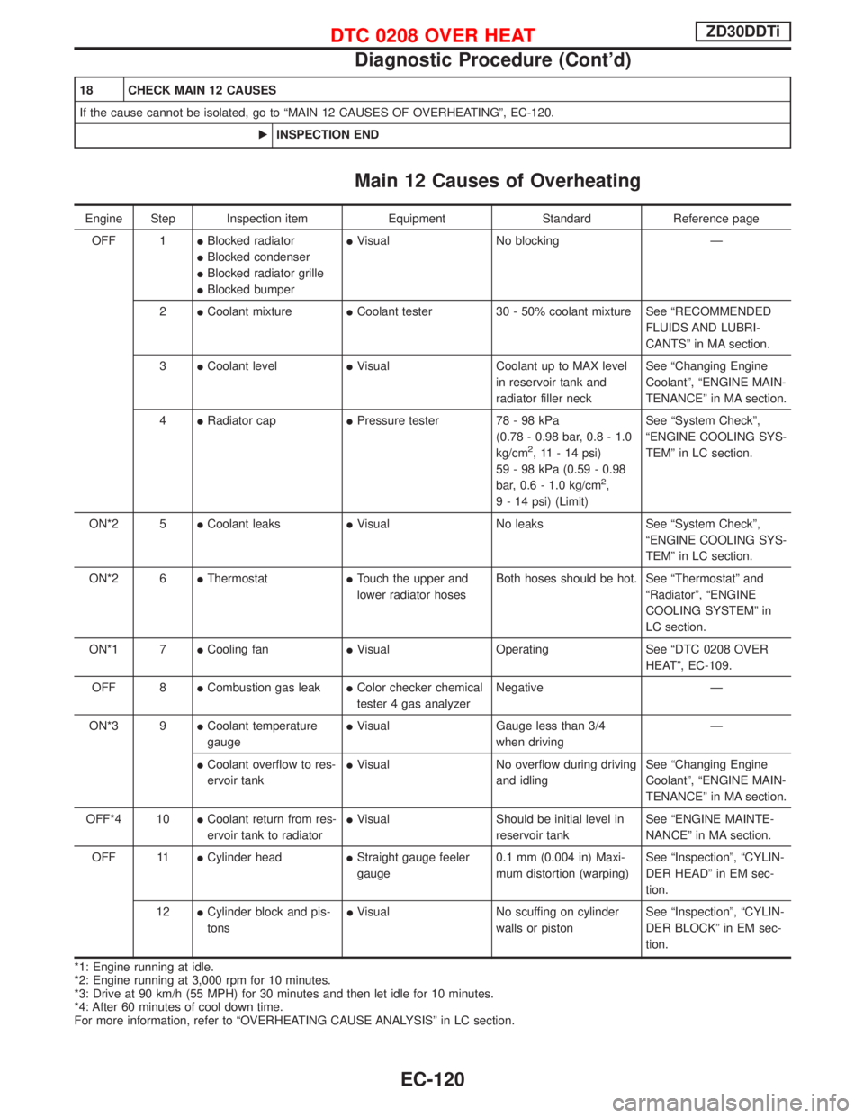
Main 12 Causes of Overheating
Engine Step Inspection item Equipment Standard Reference page
OFF 1IBlocked radiator
IBlocked condenser
IBlocked radiator grille
IBlocked bumperIVisual No blocking Ð
2ICoolant mixtureICoolant tester 30 - 50% coolant mixture See ªRECOMMENDED
FLUIDS AND LUBRI-
CANTSº in MA section.
3ICoolant levelIVisual Coolant up to MAX level
in reservoir tank and
radiator filler neckSee ªChanging Engine
Coolantº, ªENGINE MAIN-
TENANCEº in MA section.
4IRadiator capIPressure tester 78 - 98 kPa
(0.78 - 0.98 bar, 0.8 - 1.0
kg/cm
2, 11 - 14 psi)
59 - 98 kPa (0.59 - 0.98
bar, 0.6 - 1.0 kg/cm
2,
9 - 14 psi) (Limit)See ªSystem Checkº,
ªENGINE COOLING SYS-
TEMº in LC section.
ON*2 5ICoolant leaksIVisual No leaks See ªSystem Checkº,
ªENGINE COOLING SYS-
TEMº in LC section.
ON*2 6IThermostatITouch the upper and
lower radiator hosesBoth hoses should be hot. See ªThermostatº and
ªRadiatorº, ªENGINE
COOLING SYSTEMº in
LC section.
ON*1 7ICooling fanIVisual Operating See ªDTC 0208 OVER
HEATº, EC-109.
OFF 8ICombustion gas leakIColor checker chemical
tester 4 gas analyzerNegative Ð
ON*3 9ICoolant temperature
gaugeIVisual Gauge less than 3/4
when drivingÐ
ICoolant overflow to res-
ervoir tankIVisual No overflow during driving
and idlingSee ªChanging Engine
Coolantº, ªENGINE MAIN-
TENANCEº in MA section.
OFF*4 10ICoolant return from res-
ervoir tank to radiatorIVisual Should be initial level in
reservoir tankSee ªENGINE MAINTE-
NANCEº in MA section.
OFF 11ICylinder headIStraight gauge feeler
gauge0.1 mm (0.004 in) Maxi-
mum distortion (warping)See ªInspectionº, ªCYLIN-
DER HEADº in EM sec-
tion.
12ICylinder block and pis-
tonsIVisual No scuffing on cylinder
walls or pistonSee ªInspectionº, ªCYLIN-
DER BLOCKº in EM sec-
tion.
*1: Engine running at idle.
*2: Engine running at 3,000 rpm for 10 minutes.
*3: Drive at 90 km/h (55 MPH) for 30 minutes and then let idle for 10 minutes.
*4: After 60 minutes of cool down time.
For more information, refer to ªOVERHEATING CAUSE ANALYSISº in LC section.
DTC 0208 OVER HEATZD30DDTi
Diagnostic Procedure (Cont'd)
EC-120
Page 781 of 1767
Overall Function Check
Use this procedure to check the overall function of the cooling fan.
During this check, a DTC might not be confirmed.
WARNING:
Never remove the radiator cap when the engine is hot. Serious
burns could be caused by high pressure fluid escaping from
the radiator.
Wrap a thick cloth around the cap. Carefully remove the cap
by turning it a quarter turn to allow built-up pressure to
escape. Then turn the cap all the way off.
WITH CONSULT-II
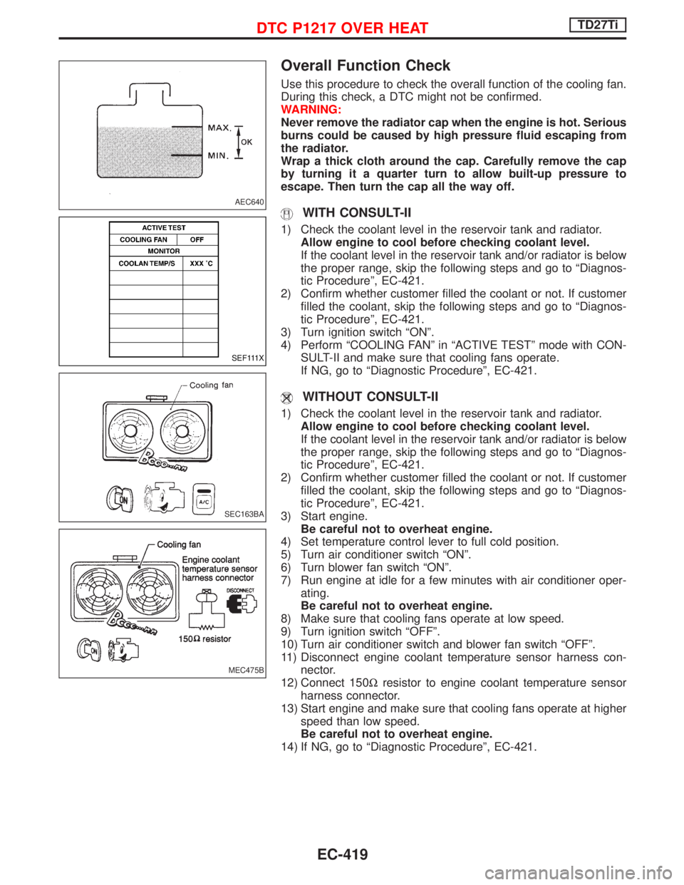
1) Check the coolant level in the reservoir tank and radiator.
Allow engine to cool before checking coolant level.
If the coolant level in the reservoir tank and/or radiator is below
the proper range, skip the following steps and go to ªDiagnos-
tic Procedureº, EC-421.
2) Confirm whether customer filled the coolant or not. If customer
filled the coolant, skip the following steps and go to ªDiagnos-
tic Procedureº, EC-421.
3) Turn ignition switch ªONº.
4) Perform ªCOOLING FANº in ªACTIVE TESTº mode with CON-
SULT-II and make sure that cooling fans operate.
If NG, go to ªDiagnostic Procedureº, EC-421.
WITHOUT CONSULT-II
1) Check the coolant level in the reservoir tank and radiator.
Allow engine to cool before checking coolant level.
If the coolant level in the reservoir tank and/or radiator is below
the proper range, skip the following steps and go to ªDiagnos-
tic Procedureº, EC-421.
2) Confirm whether customer filled the coolant or not. If customer
filled the coolant, skip the following steps and go to ªDiagnos-
tic Procedureº, EC-421.
3) Start engine.
Be careful not to overheat engine.
4) Set temperature control lever to full cold position.
5) Turn air conditioner switch ªONº.
6) Turn blower fan switch ªONº.
7) Run engine at idle for a few minutes with air conditioner oper-
ating.
Be careful not to overheat engine.
8) Make sure that cooling fans operate at low speed.
9) Turn ignition switch ªOFFº.
10) Turn air conditioner switch and blower fan switch ªOFFº.
11) Disconnect engine coolant temperature sensor harness con-
nector.
12) Connect 150Wresistor to engine coolant temperature sensor
harness connector.
13) Start engine and make sure that cooling fans operate at higher
speed than low speed.
Be careful not to overheat engine.
14) If NG, go to ªDiagnostic Procedureº, EC-421.
AEC640
SEF111X
SEC163BA
MEC475B
DTC P1217 OVER HEATTD27Ti
EC-419
Page 787 of 1767
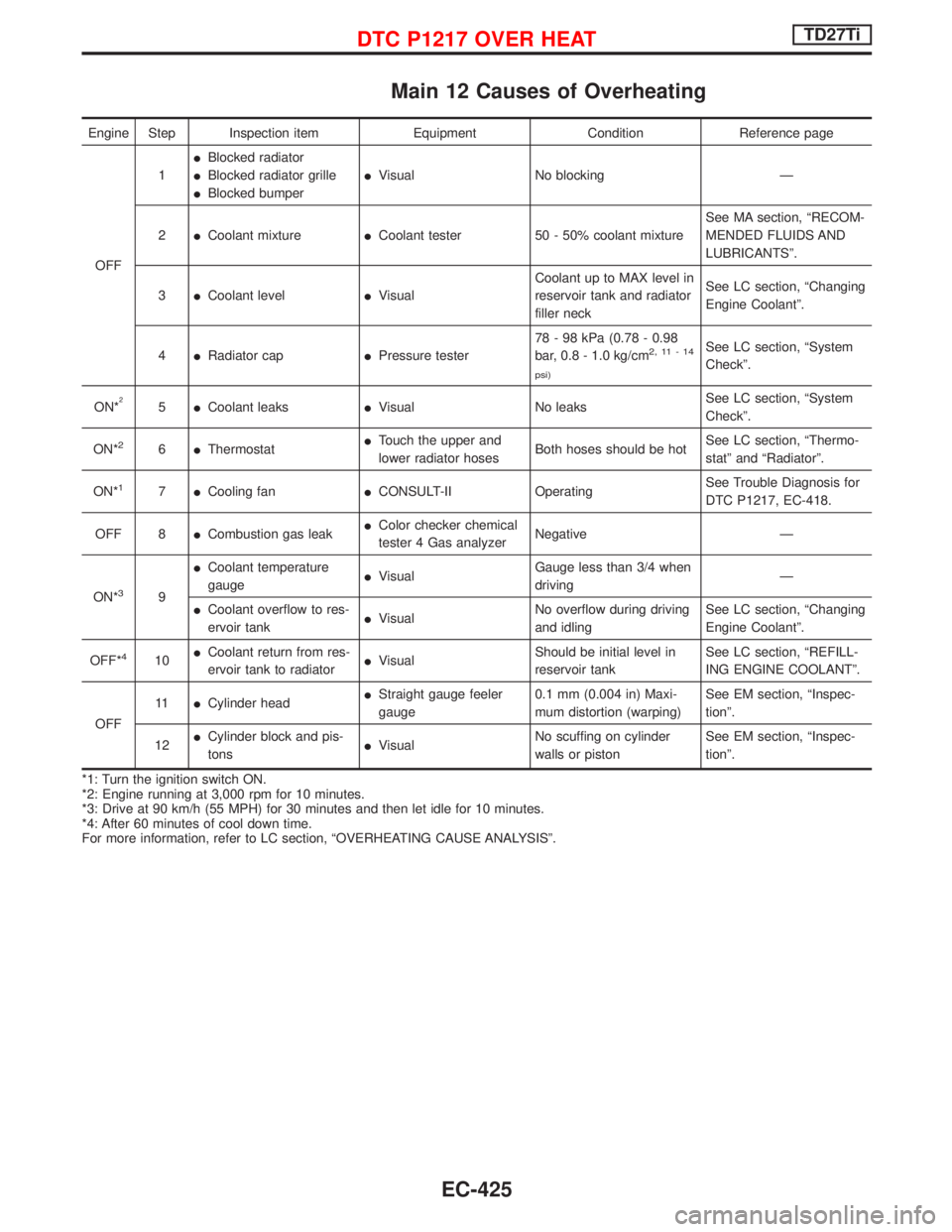
Main 12 Causes of Overheating
Engine Step Inspection item Equipment Condition Reference page
OFF1IBlocked radiator
IBlocked radiator grille
IBlocked bumperIVisual No blocking Ð
2ICoolant mixtureICoolant tester 50 - 50% coolant mixtureSee MA section, ªRECOM-
MENDED FLUIDS AND
LUBRICANTSº.
3ICoolant levelIVisualCoolant up to MAX level in
reservoir tank and radiator
filler neckSee LC section, ªChanging
Engine Coolantº.
4IRadiator capIPressure tester78 - 98 kPa (0.78 - 0.98
bar, 0.8 - 1.0 kg/cm
2,11-14
psi)See LC section, ªSystem
Checkº.
ON*
25ICoolant leaksIVisual No leaksSee LC section, ªSystem
Checkº.
ON*
26IThermostatITouch the upper and
lower radiator hosesBoth hoses should be hotSee LC section, ªThermo-
statº and ªRadiatorº.
ON*
17ICooling fanICONSULT-II OperatingSee Trouble Diagnosis for
DTC P1217, EC-418.
OFF 8ICombustion gas leakIColor checker chemical
tester 4 Gas analyzerNegative Ð
ON*
39ICoolant temperature
gaugeIVisualGauge less than 3/4 when
drivingÐ
ICoolant overflow to res-
ervoir tankIVisualNo overflow during driving
and idlingSee LC section, ªChanging
Engine Coolantº.
OFF*
410ICoolant return from res-
ervoir tank to radiatorIVisualShould be initial level in
reservoir tankSee LC section, ªREFILL-
ING ENGINE COOLANTº.
OFF11ICylinder headIStraight gauge feeler
gauge0.1 mm (0.004 in) Maxi-
mum distortion (warping)See EM section, ªInspec-
tionº.
12ICylinder block and pis-
tonsIVisualNo scuffing on cylinder
walls or pistonSee EM section, ªInspec-
tionº.
*1: Turn the ignition switch ON.
*2: Engine running at 3,000 rpm for 10 minutes.
*3: Drive at 90 km/h (55 MPH) for 30 minutes and then let idle for 10 minutes.
*4: After 60 minutes of cool down time.
For more information, refer to LC section, ªOVERHEATING CAUSE ANALYSISº.
DTC P1217 OVER HEATTD27Ti
EC-425
Page 1172 of 1767
Engine room (Left)
3. Remove air duct and air cleaner case.
4. Disconnect vacuum hose to the vehicle on the engine.
5. Disconnect harness connectors from alternator and air com-
pressor.
6. Remove alternator.
7. After removing refrigerant, remove pipes of air compressor and
inlet/outlet.
8. Disconnect heating hose, install blank cap to hose to prevent
coolant from leaking.
9. Remove heating pipe.
10. Remove heat insulator.
11. Remove catalytic converter.
Engine room (Right)
12. Remove power steering reservoir tank from bracket, and fix it
to the vehicle with a rope.
CAUTION:
Keep the reservoir tank level when fixing to prevent oil leak.
13. Remove fuel feed and return hoses.
CAUTION:
Install blank caps immediately to avoid fuel leakage.
14. Remove all harness connectors on the engine, and move har-
nesses to the side of the vehicle.
Vehicle underfloor
15. Remove starter motor.
16. Detach A/T oil cooler pipes from oil pan. (A/T model)
17. Remove rear propeller shaft.
18. Remove mounting bolts to secure the engine to transmission.
1) Remove torque converter installation bolt. (A/T model)
2) Lift transmission bottom with transmission jack, and remove
rear mount members from the vehicle.
3) Lower transmission with the jack, and remove upper mounting
bolts securing the engine to transmission.
4) Lift transmission with the jack, and reinstall rear mount mem-
bers to the vehicle.
5) Position the jack to the front side of transmission.
6) Remove remaining mounting bolts securing the engine to trans-
mission.
Removal operation
19. Remove air conditioner high pressure pipes at the rear of the
engine room.
IThis is due to some inconvenience in the rear slinger installa-
tion.
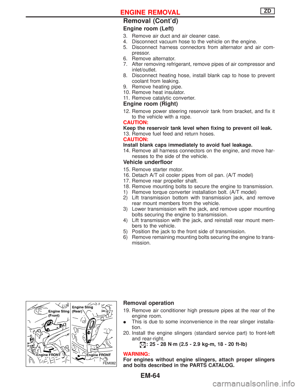
20. Install the engine slingers (standard service part) to front-left
and rear-right.
:25-28N×m (2.5 - 2.9 kg-m, 18 - 20 ft-lb)
WARNING:
For engines without engine slingers, attach proper slingers
and bolts described in the PARTS CATALOG.
FEM082
ENGINE REMOVALZD
Removal (Cont'd)
EM-64
Page 1440 of 1767
REMOVAL AND INSTALLATION
1. Remove under cover.
2. Drain engine coolant. Refer to MA section, ªChanging Engine
Coolantº.
3. Remove air cleaner case, air duct and resonator.
4. Remove battery (right side).
5. Remove radiator shroud (lower).
6. Remove radiator shroud (front).
7. Disconnect radiator hose (upper and lower).
8. Disconnect reservoir tank hose.
9. Disconnect A/T oil cooler hose (Only A/T models).
10. Remove radiator.
11. After repairing or replacing radiator, install all removed parts in
reverse order of removal.
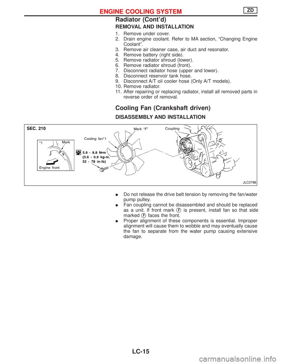
Cooling Fan (Crankshaft driven)
DISASSEMBLY AND INSTALLATION
IDo not release the drive belt tension by removing the fan/water
pump pulley.
IFan coupling cannot be disassembled and should be replaced
as a unit. If front markq
Fis present, install fan so that side
markedq
Ffaces the front.
IProper alignment of these components is essential. Improper
alignment will cause them to wobble and may eventually cause
the fan to separate from the water pump causing extensive
damage.
JLC379B
ENGINE COOLING SYSTEMZD
Radiator (Cont'd)
LC-15
Page 1462 of 1767
Shown below are Pre-delivery Inspection items required for the new vehicle. It is recommended that
necessary items other than those listed here be added, paying due regard to the conditions in each
country.
Perform applicable items on each model. Consult text of this section for specifications.
UNDER HOOD Ð engine off
lRadiator coolant level and coolant hose connections for leaks
lBattery fluid level, specific gravity and conditions of battery terminals
lBrake and clutch reservoirs fluid level and fluid lines for leaks
lWindshield and rear window washer and headlamp cleaner reservoir fluid level
lDrive belts tension
lFuel filter for water or dust, and fuel lines and connections for leaks
lPower steering reservoir fluid level and hose connections for leaks
lEngine oil level and oil leaks
INSIDE AND OUTSIDE
lOperation of all instruments, gauges, lights, anti-theft system and accessories
lOperation of horn(s), wiper and washer
lSteering lock for operation
lAir conditioner for gas leaks
lFront and rear seats, and seat belts for operation
lAll moldings, trims and fittings for fit and alignment
lAll windows for operation and alignment
lHood, tailgate, door panels for fit and alignment
lLatches, keys and locks for operation
lWeatherstrips for adhesion and fit
lHeadlamp aiming
lTighten wheel nuts
lTire pressure (Inc. spare tire)
lCheck front wheels for toe-in
lInstall clock/room lamp fuse
lRemove wiper blade protectors (if necessary)
UNDER BODY
lManual transmission/transaxle and differential gear oil level
lBrake and fuel lines and oil/fluid reservoirs for leaks
lTighten bolts and nuts of steering linkage and gear box, suspension, propeller shafts and drive shafts
ROAD TEST
lClutch operation
lParking brake operation
lService brake operation
lSteering control and returnability
lEngine performance
lSqueaks and rattles
ENGINE OPERATING AND HOT
lAdjust idle mixture and speed (and ignition timing) (Petrol only)
FINAL INSPECTION
lInstall necessary parts (outside mirror, wheel covers, seat belts, mat, carpet or mud flaps)
lInspect for interior and exterior metal and paint damage
lCheck for spare tire, jack, tools and literature
lWash, clean interior and exterior
PRE-DELIVERY INSPECTION ITEMS
MA-3
Page 1463 of 1767
General maintenance includes those items which should be checked during normal day-to-day operation of
the vehicle. They are essential if the vehicle is to continue functioning correctly. Owners can perform the
checks and inspections themselves, or they can be carried out by a NISSAN dealer.
Item Reference pages
OUTSIDE THE VEHICLE
The maintenance items listed here should be checked periodically, unless otherwise specified.
TiresCheck the pressure with a gauge weekly when at a service station, including the spare,
and adjust to the specified pressure if necessary. Check carefully for damage, cuts or excessive
wear.Ð
Windshield wiper bladesCheck for cracks or wear if not functioning correctly. Ð
Doors and engine hoodCheck that all doors, the engine hood, the trunk lid and back door
function correctly. Also ensure that all latches lock securely. Lubricate if necessary. Make sure
that the secondary latch prevents the hood from opening when the primary latch is released.
When driving in areas using road salt or other corrosive materials, check for lubrication more
often.MA-45
Tire rotationTires should be rotated every 5,000 km (3,000 miles). MA-43
INSIDE THE VEHICLE
The maintenance items listed here should be checked on a regular basis, such as when per-
forming periodic maintenance, cleaning the vehicle etc.
LightsMake sure that the headlights, stop lights, tail lights, turn signal lights, and other lights
are all operating correctly and installed securely. Also check headlight aim.Ð
Warning lights and buzzers/chimesMake sure that all warning lights and buzzers/chimes are
functioning correctly.Ð
Steering wheelCheck that it has the specified play. Check for changes in the steering
operation, such as excessive free play, hard steering or strange noises.
Free play: Less than 35 mm (1.38 in)Ð
Seat beltsCheck that all parts of the seat belt system (e.g. buckles, anchors, adjusters and
retractors) operate properly and smoothly, and are installed securely. Check the belt webbing for
cuts, fraying, wear of damage.MA-46
UNDER THE HOOD AND VEHICLE
The maintenance items listed here should be checked periodically e.g. each time you check the
engine oil or refuel.
Windshield washer fluidCheck that there is adequate fluid in the tank.
Engine coolant levelCheck the coolant level when the engine is cold. MA-22
Engine oil levelCheck the level after parking the vehicle (on level ground) and turning off the
engine.MA-21
Brake and clutch fluid levelMake sure that the brake fluid level is between the ªMAXº and
ªMINº lines on the reservoir.MA-36/MA-40
BatteryCheck the fluid level in each cell. It should be between the ªMAXº and ªMINº lines. Ð
GENERAL MAINTENANCE
MA-4
Page 1476 of 1767
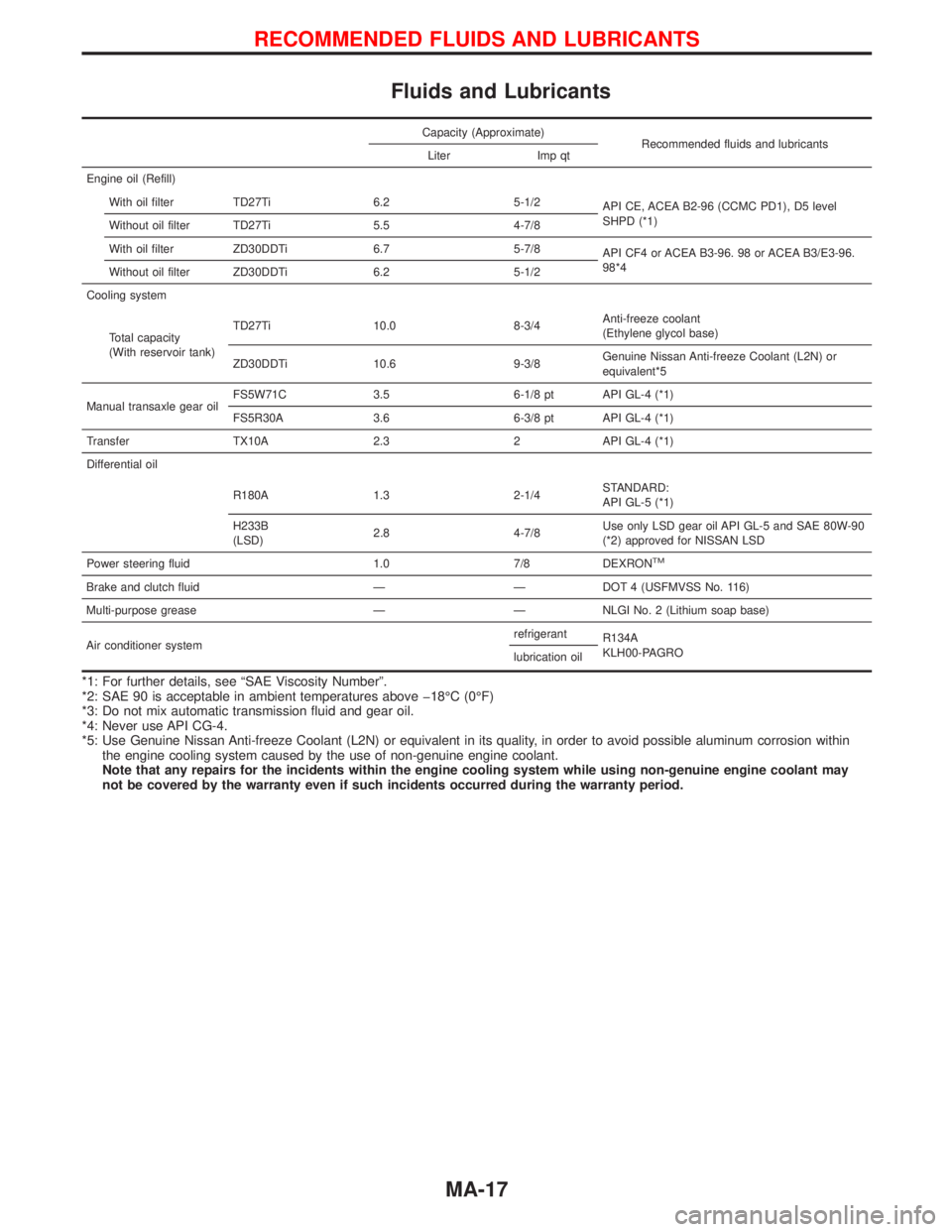
Fluids and Lubricants
Capacity (Approximate)
Recommended fluids and lubricants
Liter Imp qt
Engine oil (Refill)
With oil filter TD27Ti 6.2 5-1/2
API CE, ACEA B2-96 (CCMC PD1), D5 level
SHPD (*1)
Without oil filter TD27Ti 5.5 4-7/8
With oil filter ZD30DDTi 6.7 5-7/8
API CF4 or ACEA B3-96. 98 or ACEA B3/E3-96.
98*4
Without oil filter ZD30DDTi 6.2 5-1/2
Cooling system
Total capacity
(With reservoir tank)TD27Ti 10.0 8-3/4Anti-freeze coolant
(Ethylene glycol base)
ZD30DDTi 10.6 9-3/8Genuine Nissan Anti-freeze Coolant (L2N) or
equivalent*5
Manual transaxle gear oilFS5W71C 3.5 6-1/8 pt API GL-4 (*1)
FS5R30A 3.6 6-3/8 pt API GL-4 (*1)
Transfer TX10A 2.3 2 API GL-4 (*1)
Differential oil
R180A 1.3 2-1/4STANDARD:
API GL-5 (*1)
H233B
(LSD)2.8 4-7/8Use only LSD gear oil API GL-5 and SAE 80W-90
(*2) approved for NISSAN LSD
Power steering fluid 1.0 7/8 DEXRON
TM
Brake and clutch fluid Ð Ð DOT 4 (USFMVSS No. 116)
Multi-purpose grease Ð Ð NLGI No. 2 (Lithium soap base)
Air conditioner systemrefrigerant
R134A
KLH00-PAGRO
lubrication oil
*1: For further details, see ªSAE Viscosity Numberº.
*2: SAE 90 is acceptable in ambient temperatures above þ18ÉC (0ÉF)
*3: Do not mix automatic transmission fluid and gear oil.
*4: Never use API CG-4.
*5: Use Genuine Nissan Anti-freeze Coolant (L2N) or equivalent in its quality, in order to avoid possible aluminum corrosion within
the engine cooling system caused by the use of non-genuine engine coolant.
Note that any repairs for the incidents within the engine cooling system while using non-genuine engine coolant may
not be covered by the warranty even if such incidents occurred during the warranty period.
RECOMMENDED FLUIDS AND LUBRICANTS
MA-17
Page 1481 of 1767
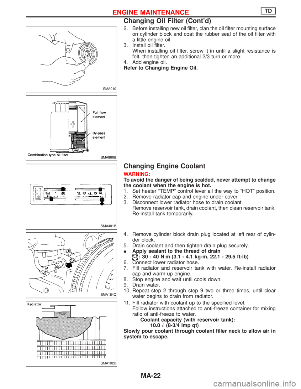
2. Before installing new oil filter, clan the oil filter mounting surface
on cylinder block and coat the rubber seal of the oil filter with
a little engine oil.
3. Install oil filter.
When installing oil filter, screw it in until a slight resistance is
felt, then tighten an additional 2/3 turn or more.
4. Add engine oil.
Refer to Changing Engine Oil.
Changing Engine Coolant
WARNING:
To avoid the danger of being scalded, never attempt to change
the coolant when the engine is hot.
1. Set heater ªTEMPº control lever all the way to ªHOTº position.
2. Remove radiator cap and engine under cover.
3. Disconnect lower radiator hose to drain coolant.
Remove reservoir tank, drain coolant, then clean reservoir tank.
Re-install tank temporarily.
4. Remove cylinder block drain plug located at left rear of cylin-
der block.
5. Drain coolant and then tighten drain plug securely.
IApply sealant to the thread of drain
:30-40N×m (3.1 - 4.1 kg-m, 22.1 - 29.5 ft-lb)
6. Connect lower radiator hose.
7. Fill radiator and reservoir tank with water. Re-install radiator
cap and warm up engine.
8. Stop engine and wait until cools down.
9. Drain water.
10. Repeat step 2 through step 9 two or three times, until clear
water begins to drain from radiator.
11. Fill radiator with coolant up to the specified level.
Follow instructions attached to anti-freeze container for mixing
ratio of anti-freeze to water.
Coolant capacity (with reservoir tank):
10.0(8-3/4 Imp qt)
Slowly pour coolant through coolant filler neck to allow air in
system to escape.
SMA010
SMA860B
SMA401B
SMA164C
SMA182B
ENGINE MAINTENANCETD
Changing Oil Filter (Cont'd)
MA-22