pump NISSAN TERRANO 2002 Service Repair Manual
[x] Cancel search | Manufacturer: NISSAN, Model Year: 2002, Model line: TERRANO, Model: NISSAN TERRANO 2002Pages: 1767, PDF Size: 41.51 MB
Page 4 of 1767
1. SPORT Indicator Lamp Does Not Come On ........94
2. SPORT or SNOW Indicator Lamp Does Not
Come On...................................................................95
3. O/D OFF Indicator Lamp Does Not Come On......95
4. SPORT Indicator Lamp Does Not Come On ........96
5. Engine Cannot Be Started In²P²and²N²
Position......................................................................97
6. In²P²Position, Vehicle Moves Forward Or
Backward When Pushed...........................................97
7. In²N²Position, Vehicle Moves .............................98
8. Large Shock.²N²->²R²Position .........................99
9. Vehicle Does Not Creep Backward In²R²
Position....................................................................100
10. Vehicle Does Not Creep Forward In²D²,²2²
Or²1²Position.........................................................101
11. Vehicle Cannot Be Started From D
1.................102
12. A/T Does Not Shift: D
1-> D2Or Does Not
Kickdown: D
4-> D2..................................................103
13. A/T Does Not Shift: D
2-> D3............................104
14. A/T Does Not Shift: D
3-> D4.............................105
15. A/T Does Not Perform Lock-up .........................106
16. A/T Does Not Hold Lock-up Condition ..............107
17. Lock-up Is Not Released ...................................107
18. Engine Speed Does Not Return To Idle (Light
Braking D
4-> D3) .....................................................108
19. Vehicle Does Not Start From D
1.......................109
20. A/T Does Not Shift: D
2-> D1When
Depressing Accelerator Pedal................................. 110
21. A/T Does Not Shift: D
4-> D3, When
Overdrive Control Switch²ON²->²OFF²............... 111
22. A/T Does Not Shift: D
3-> 22, When Selector
Lever²D²->²2²Position......................................... 111
23. A/T Does Not Shift: 2
2-> 11, When Selector
Lever²2²->²1²Position ......................................... 112
24. Vehicle Does Not Decelerate By Engine
Brake........................................................................ 112
ON-VEHICLE SERVICE.............................................. 113Control Valve Assembly and Accumulators ............. 113
Revolution Sensor Replacement ............................. 114
Rear Oil Seal Replacement ..................................... 114
Parking Components Inspection.............................. 114
Park/neutral Position Switch Adjustment ................. 114
Manual Control Linkage Adjustment........................ 115
REMOVAL AND INSTALLATION................................ 116
Removal ................................................................... 116
Installation ................................................................ 117
MAJOR OVERHAUL................................................... 119
Oil Channel ..............................................................121
Locations of Needle Bearings, Thrust Washers
and Snap Rings .......................................................122
DISASSEMBLY............................................................123
Disassembly.............................................................123
REPAIR FOR COMPONENT PARTS..........................134
Oil Pump ..................................................................134
Control Valve Assembly ...........................................138
Control Valve Upper Body .......................................144
Control Valve Lower Body .......................................149
Reverse Clutch ........................................................151
High Clutch ..............................................................155
Forward and Overrun Clutches ...............................157
Low & Reverse Brake..............................................161
Forward Clutch Drum Assembly ..............................165
Rear Internal Gear and Forward Clutch Hub ..........168
Band Servo Piston Assembly ..................................171
Parking Pawl Components ......................................175
ASSEMBLY..................................................................177
Assembly (1) ............................................................177
Adjustment ...............................................................185
Assembly (2) ............................................................188
A/T FLUID COOLER SYSTEM...................................195
A/T Fluid Cooler.......................................................195
SERVICE DATA AND SPECIFICATIONS (SDS)........196
General Specifications .............................................196
Specifications and Adjustment.................................196
When you read wiring diagrams:
IRead GI section, ªHOW TO READ WIRING DIAGRAMSº.
ISee EL section, ªPOWER SUPPLY ROUTINGº for power distribution circuit.
When you perform trouble diagnoses, read GI section, ªHOW TO FOLLOW FLOW CHART IN
TROUBLE DIAGNOSESº and ªHOW TO PERFORM EFFICIENT DIAGNOSIS FOR AN ELECTRI-
CAL INCIDENTº.
CONTENTS(Cont'd)
AT- 2
Page 5 of 1767
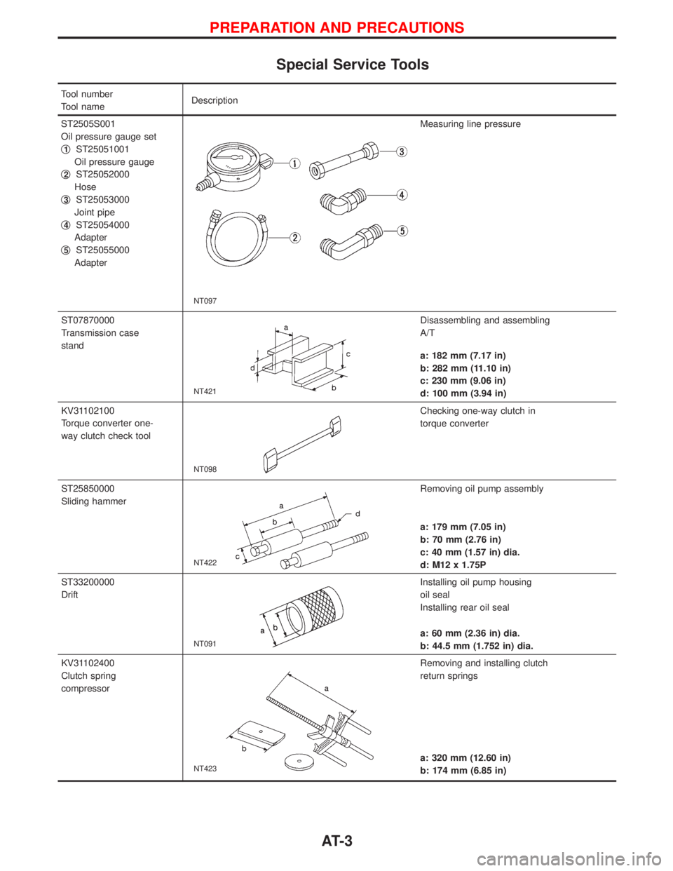
Special Service Tools
Tool number
Tool nameDescription
ST2505S001
Oil pressure gauge set
q
1ST25051001
Oil pressure gauge
q
2ST25052000
Hose
q
3ST25053000
Joint pipe
q
4ST25054000
Adapter
q
5ST25055000
Adapter
NT097
Measuring line pressure
ST07870000
Transmission case
stand
NT421
Disassembling and assembling
A/T
a: 182 mm (7.17 in)
b: 282 mm (11.10 in)
c: 230 mm (9.06 in)
d: 100 mm (3.94 in)
KV31102100
Torque converter one-
way clutch check tool
NT098
Checking one-way clutch in
torque converter
ST25850000
Sliding hammer
NT422
Removing oil pump assembly
a: 179 mm (7.05 in)
b: 70 mm (2.76 in)
c: 40 mm (1.57 in) dia.
d: M12 x 1.75P
ST33200000
Drift
NT091
Installing oil pump housing
oil seal
Installing rear oil seal
a: 60 mm (2.36 in) dia.
b: 44.5 mm (1.752 in) dia.
KV31102400
Clutch spring
compressor
NT423
Removing and installing clutch
return springs
a: 320 mm (12.60 in)
b: 174 mm (6.85 in)
PREPARATION AND PRECAUTIONS
AT- 3
Page 12 of 1767
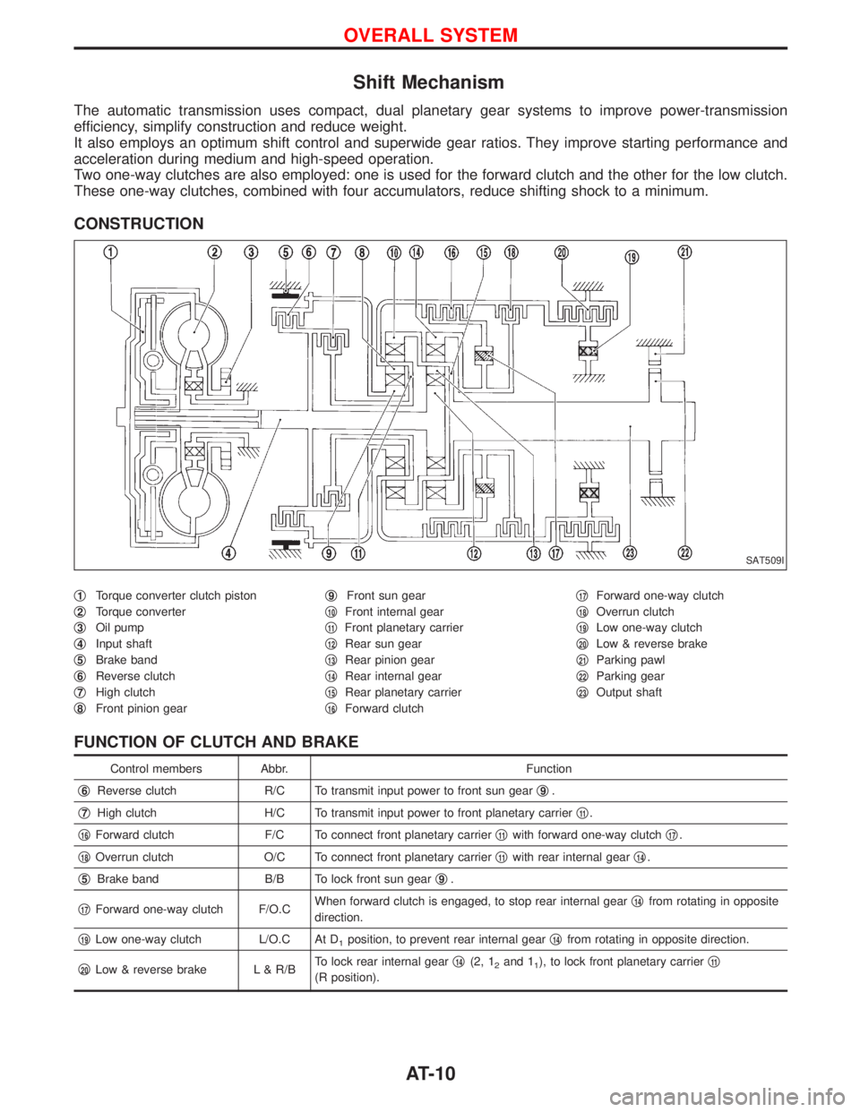
Shift Mechanism
The automatic transmission uses compact, dual planetary gear systems to improve power-transmission
efficiency, simplify construction and reduce weight.
It also employs an optimum shift control and superwide gear ratios. They improve starting performance and
acceleration during medium and high-speed operation.
Two one-way clutches are also employed: one is used for the forward clutch and the other for the low clutch.
These one-way clutches, combined with four accumulators, reduce shifting shock to a minimum.
CONSTRUCTION
q1Torque converter clutch piston
q
2Torque converter
q
3Oil pump
q
4Input shaft
q
5Brake band
q
6Reverse clutch
q
7High clutch
q
8Front pinion gearq
9Front sun gear
q
10Front internal gear
q
11Front planetary carrier
q
12Rear sun gear
q
13Rear pinion gear
q
14Rear internal gear
q
15Rear planetary carrier
q
16Forward clutchq
17Forward one-way clutch
q
18Overrun clutch
q
19Low one-way clutch
q
20Low & reverse brake
q
21Parking pawl
q
22Parking gear
q
23Output shaft
FUNCTION OF CLUTCH AND BRAKE
Control members Abbr. Function
q
6Reverse clutch R/C To transmit input power to front sun gearq9.
q
7High clutch H/C To transmit input power to front planetary carrierq11.
q
16Forward clutch F/C To connect front planetary carrierq11with forward one-way clutchq17.
q
18Overrun clutch O/C To connect front planetary carrierq11with rear internal gearq14.
q
5Brake band B/B To lock front sun gearq9.
q
17Forward one-way clutch F/O.CWhen forward clutch is engaged, to stop rear internal gearq14from rotating in opposite
direction.
q
19Low one-way clutch L/O.C At D1position, to prevent rear internal gearq14from rotating in opposite direction.
q
20Low & reverse brake L & R/BTo lock rear internal gearq14(2, 12and 11), to lock front planetary carrierq11
(R position).
SAT509I
OVERALL SYSTEM
AT-10
Page 33 of 1767
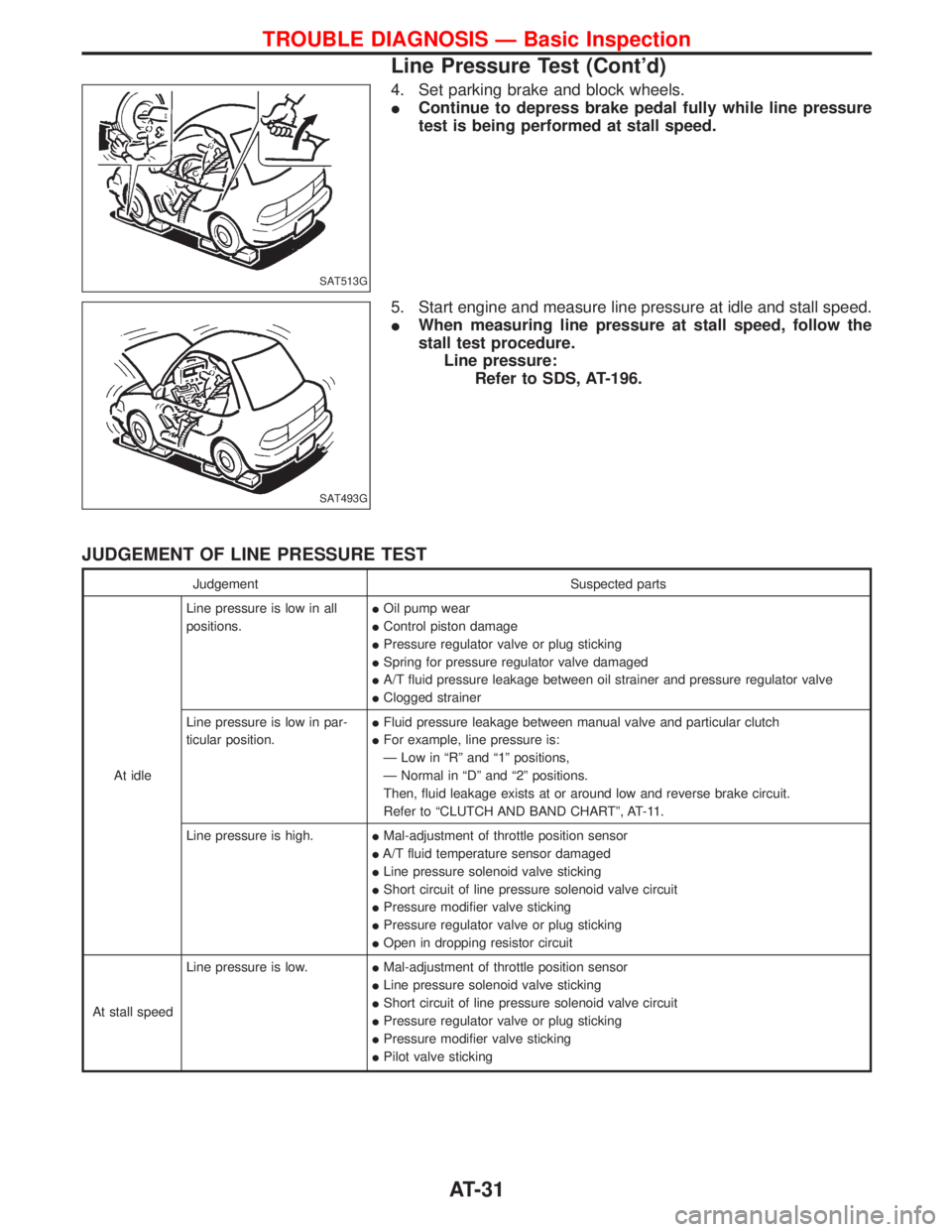
4. Set parking brake and block wheels.
IContinue to depress brake pedal fully while line pressure
test is being performed at stall speed.
5. Start engine and measure line pressure at idle and stall speed.
IWhen measuring line pressure at stall speed, follow the
stall test procedure.
Line pressure:
Refer to SDS, AT-196.
JUDGEMENT OF LINE PRESSURE TEST
Judgement Suspected parts
At idleLine pressure is low in all
positions.IOil pump wear
IControl piston damage
IPressure regulator valve or plug sticking
ISpring for pressure regulator valve damaged
IA/T fluid pressure leakage between oil strainer and pressure regulator valve
IClogged strainer
Line pressure is low in par-
ticular position.IFluid pressure leakage between manual valve and particular clutch
IFor example, line pressure is:
Ð Low in ªRº and ª1º positions,
Ð Normal in ªDº and ª2º positions.
Then, fluid leakage exists at or around low and reverse brake circuit.
Refer to ªCLUTCH AND BAND CHARTº, AT-11.
Line pressure is high.IMal-adjustment of throttle position sensor
IA/T fluid temperature sensor damaged
ILine pressure solenoid valve sticking
IShort circuit of line pressure solenoid valve circuit
IPressure modifier valve sticking
IPressure regulator valve or plug sticking
IOpen in dropping resistor circuit
At stall speedLine pressure is low.IMal-adjustment of throttle position sensor
ILine pressure solenoid valve sticking
IShort circuit of line pressure solenoid valve circuit
IPressure regulator valve or plug sticking
IPressure modifier valve sticking
IPilot valve sticking
SAT513G
SAT493G
TROUBLE DIAGNOSIS Ð Basic Inspection
Line Pressure Test (Cont'd)
AT-31
Page 45 of 1767
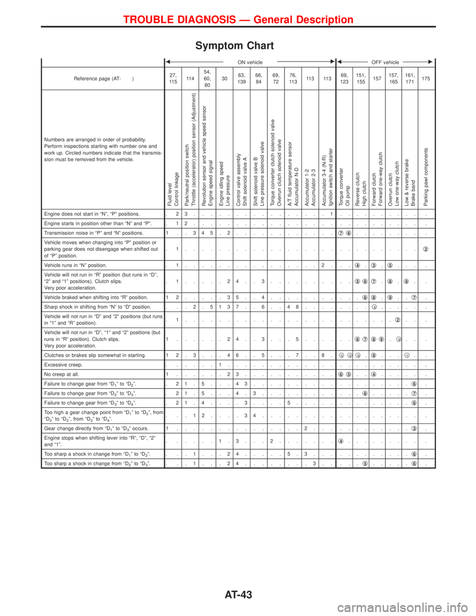
Symptom Chart
FON vehicleEFOFF vehicleE
Reference page (AT- )27,
11 511 454,
60,
803063,
13966,
8469,
7276,
11 311 3 11 369,
123151,
155157157,
165161,
171175
Numbers are arranged in order of probability.
Perform inspections starting with number one and
work up. Circled numbers indicate that the transmis-
sion must be removed from the vehicle.
Fluid level
Control linkage
Park/neutral position switch
Throttle (accelerator) position sensor (Adjustment)
Revolution sensor and vehicle speed sensor
Engine speed signal
Engine idling speed
Line pressure
Control valve assembly
Shift solenoid valve A
Shift solenoid valve B
Line pressure solenoid valve
Torque converter clutch solenoid valve
Overrun clutch solenoid valve
A/T fluid temperature sensor
Accumulator N-D
Accumulator 1-2
Accumulator 2-3
Accumulator 3-4 (N-R)
Ignition switch and starter
Torque converter
Oil pump
Reverse clutch
High clutch
Forward clutch
Forward one-way clutch
Overrun clutch
Low one-way clutch
Low & reverse brake
Brake band
Parking pawl components
Engine does not start in ªNº, ªPº positions. . 2 3................1.......... .
Engine starts in position other than ªNº and ªPº. . 1 2................. .......... .
Transmission noise in ªPº and ªNº positions. 1 . . 3 4 5 . 2............q
7q6........ .
Vehicle moves when changing into ªPº position or
parking gear does not disengage when shifted out
of ªPº position.. 1.................. ..........q
2
Vehicle runs in ªNº position. . 1................2. ..q4.q3.q5... .
Vehicle will not run in ªRº position (but runs in ªDº,
ª2º and ª1º positions). Clutch slips.
Very poor acceleration.. 1.....24..3........ ..q
5q6q7.q8.q9..
Vehicle braked when shifting into ªRº position. 1 2.....35..4........ ...q
6q8.q9..q7.
Sharp shock in shifting from ªNº to ªDº position. . . . 2 .5137 . . 6 . . 48.... ....q
10..... .
Vehicle will not run in ªDº and ª2º positions (but runs
in ª1º and ªRº position).. 1.................. .......q
2.. .
Vehicle will not run in ªDº, ª1º and ª2º positions (but
runs in ªRº position). Clutch slips.
Very poor acceleration.1 ......24..3...5.... ..q
6q7q8q9.q10.. .
Clutches or brakes slip somewhat in starting. 1 2 . 3 . . . 4 6 . . 5 . . . 7 . . 8 .q
13q12q10.q9...q11..
Excessive creep. ......1............. .......... .
No creep at all. 1......23...........q
6q5..q4..... .
Failure to change gear from ªD
1ºtoªD2º. . 21.5...43.......... .........q6.
Failure to change gear from ªD
2ºtoªD3º. . 21.5...4.3......... ...q6.....q7.
Failure to change gear from ªD
3ºtoªD4º. . 21.4....3....5..... .........q6.
Too high a gear change point from ªD
1ºtoªD2º, from
ªD2ºtoªD3º, from ªD3ºtoªD4º.. ..12....34......... .......... .
Gear change directly from ªD
1ºtoªD3º occurs. 1...............2... .........q3.
Engine stops when shifting lever into ªRº, ªDº, ª2º
and ª1º.. .....1.3...2.......q
4......... .
Too sharp a shock in change from ªD
1ºtoªD2º. . ..1...24.....5.3... .........q6.
Too sharp a shock in change from ªD
2ºtoªD3º. . ..1...24........3.. ...q5.....q6.
TROUBLE DIAGNOSIS Ð General Description
AT-43
Page 46 of 1767
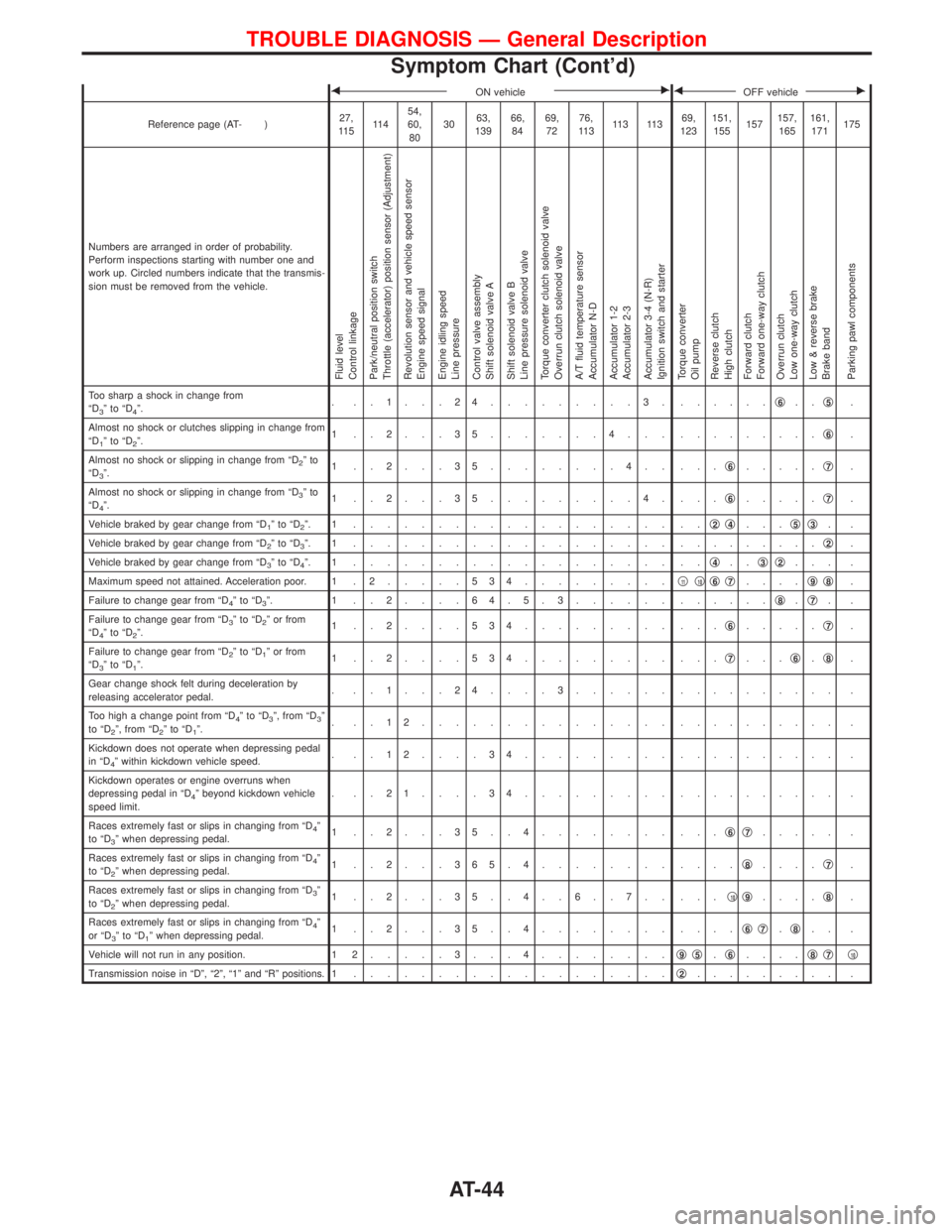
FON vehicleEFOFF vehicleE
Reference page (AT- )27,
11 511 454,
60,
803063,
13966,
8469,
7276,
11 311 3 11 369,
123151,
155157157,
165161,
171175
Numbers are arranged in order of probability.
Perform inspections starting with number one and
work up. Circled numbers indicate that the transmis-
sion must be removed from the vehicle.
Fluid level
Control linkage
Park/neutral position switch
Throttle (accelerator) position sensor (Adjustment)
Revolution sensor and vehicle speed sensor
Engine speed signal
Engine idling speed
Line pressure
Control valve assembly
Shift solenoid valve A
Shift solenoid valve B
Line pressure solenoid valve
Torque converter clutch solenoid valve
Overrun clutch solenoid valve
A/T fluid temperature sensor
Accumulator N-D
Accumulator 1-2
Accumulator 2-3
Accumulator 3-4 (N-R)
Ignition switch and starter
Torque converter
Oil pump
Reverse clutch
High clutch
Forward clutch
Forward one-way clutch
Overrun clutch
Low one-way clutch
Low & reverse brake
Brake band
Parking pawl components
Too sharp a shock in change from
ªD3ºtoªD4º.. ..1...24.........3. ......q6..q5.
Almost no shock or clutches slipping in change from
ªD
1ºtoªD2º.1 ..2...35.......4... .........q6.
Almost no shock or slipping in change from ªD
2ºto
ªD3º.1 ..2...35........4.. ...q6.....q7.
Almost no shock or slipping in change from ªD
3ºto
ªD4º.1 ..2...35.........4. ...q6.....q7.
Vehicle braked by gear change from ªD
1ºtoªD2º. 1 ................... ..q2q4...q5q3..
Vehicle braked by gear change from ªD
2ºtoªD3º. 1 ................... .........q2.
Vehicle braked by gear change from ªD
3ºtoªD4º. 1 ................... ..q4..q3q2... .
Maximum speed not attained. Acceleration poor. 1 . 2.....534.........q
11q10q6q7....q9q8.
Failure to change gear from ªD
4ºtoªD3º. 1 ..2....64.5.3...... ......q8.q7..
Failure to change gear from ªD
3ºtoªD2º or from
ªD4ºtoªD2º.1 ..2....534......... ...q6.....q7.
Failure to change gear from ªD
2ºtoªD1º or from
ªD3ºtoªD1º.1 ..2....534......... ...q7...q6.q8.
Gear change shock felt during deceleration by
releasing accelerator pedal.. ..1...24....3...... .......... .
Too high a change point from ªD
4ºtoªD3º, from ªD3º
to ªD2º, from ªD2ºtoªD1º.. ..12............... .......... .
Kickdown does not operate when depressing pedal
in ªD
4º within kickdown vehicle speed.. ..12....34......... .......... .
Kickdown operates or engine overruns when
depressing pedal in ªD
4º beyond kickdown vehicle
speed limit.. ..21....34......... .......... .
Races extremely fast or slips in changing from ªD
4º
to ªD3º when depressing pedal.1 ..2...35..4........ ...q6q7..... .
Races extremely fast or slips in changing from ªD
4º
to ªD2º when depressing pedal.1 ..2...365.4........ ....q8....q7.
Races extremely fast or slips in changing from ªD
3º
to ªD2º when depressing pedal.1 ..2...35..4..6..7.. ...q10q9....q8.
Races extremely fast or slips in changing from ªD
4º
or ªD3ºtoªD1º when depressing pedal.1 ..2...35..4........ ....q6q7.q8.. .
Vehicle will not run in any position. 1 2.....3...4........q
9q5.q6....q8q7q10
Transmission noise in ªDº, ª2º, ª1º and ªRº positions. 1...................q2......... .
TROUBLE DIAGNOSIS Ð General Description
Symptom Chart (Cont'd)
AT-44
Page 47 of 1767
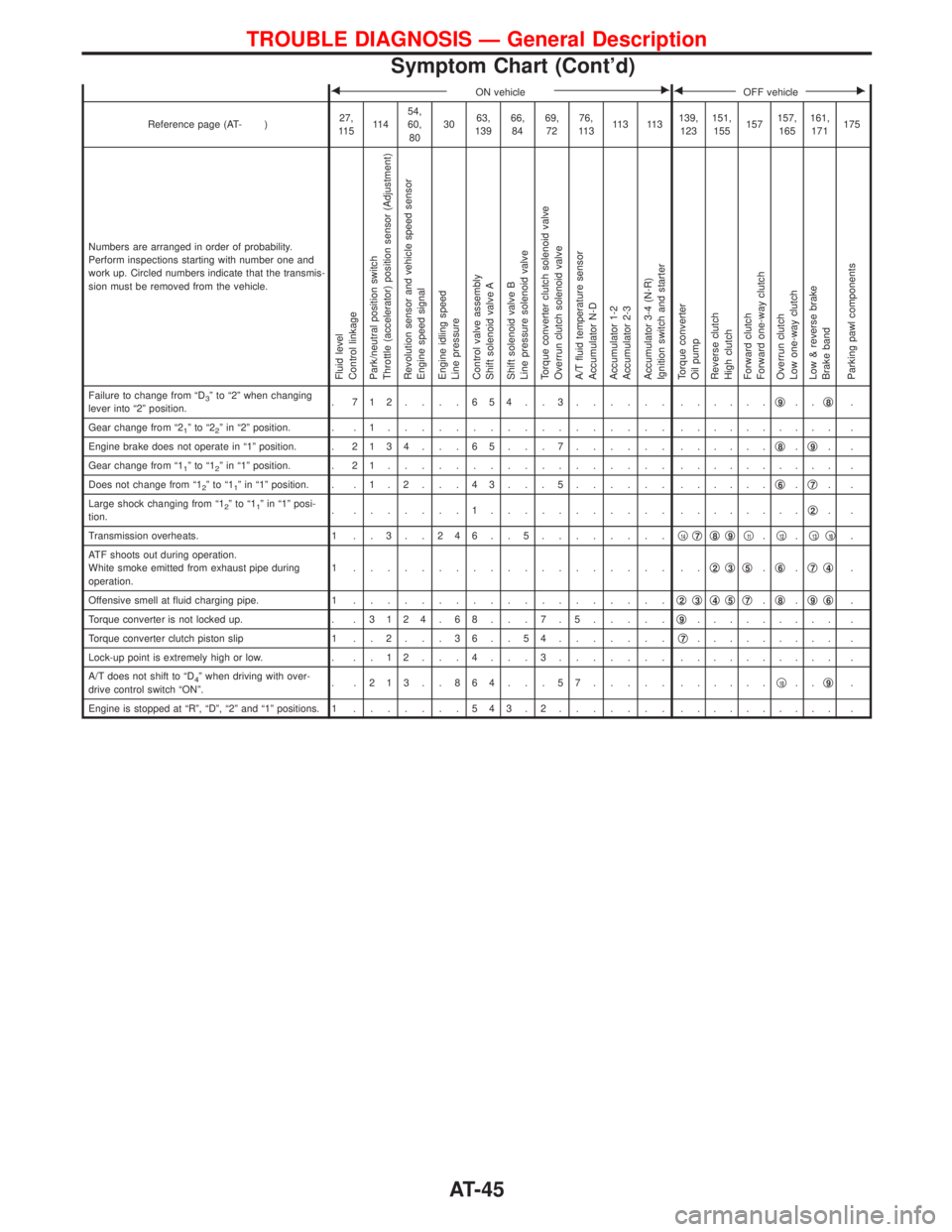
FON vehicleEFOFF vehicleE
Reference page (AT- )27,
11 511 454,
60,
803063,
13966,
8469,
7276,
11 311 3 11 3139,
123151,
155157157,
165161,
171175
Numbers are arranged in order of probability.
Perform inspections starting with number one and
work up. Circled numbers indicate that the transmis-
sion must be removed from the vehicle.
Fluid level
Control linkage
Park/neutral position switch
Throttle (accelerator) position sensor (Adjustment)
Revolution sensor and vehicle speed sensor
Engine speed signal
Engine idling speed
Line pressure
Control valve assembly
Shift solenoid valve A
Shift solenoid valve B
Line pressure solenoid valve
Torque converter clutch solenoid valve
Overrun clutch solenoid valve
A/T fluid temperature sensor
Accumulator N-D
Accumulator 1-2
Accumulator 2-3
Accumulator 3-4 (N-R)
Ignition switch and starter
Torque converter
Oil pump
Reverse clutch
High clutch
Forward clutch
Forward one-way clutch
Overrun clutch
Low one-way clutch
Low & reverse brake
Brake band
Parking pawl components
Failure to change from ªD3º to ª2º when changing
lever into ª2º position.. 712....654..3...... ......q9..q8.
Gear change from ª2
1ºtoª22º in ª2º position. . . 1................. .......... .
Engine brake does not operate in ª1º position. .2134 . . . 65 . . . 7...... ......q
8.q9..
Gear change from ª1
1ºtoª12º in ª1º position. . 2 1................. .......... .
Does not change from ª1
2ºtoª11º in ª1º position. . . 1 . 2 . . . 4 3 . . . 5...... ......q6.q7..
Large shock changing from ª1
2ºtoª11º in ª1º posi-
tion.. .......1........... ........q2..
Transmission overheats. 1 . . 3 . . 2 4 6 . . 5........q
14q7q8q9q11.q12.q13q10.
ATF shoots out during operation.
White smoke emitted from exhaust pipe during
operation.1 ................... ..q
2q3q5.q6.q7q4.
Offensive smell at fluid charging pipe. 1...................q
2q3q4q5q7.q8.q9q6.
Torque converter is not locked up. . .3124 . 68 . . . 7 . 5.....q
9......... .
Torque converter clutch piston slip 1 . . 2 . . . 3 6 . . 5 4.......q
7......... .
Lock-up point is extremely high or low. . . . 1 2 . . . 4 . . . 3....... .......... .
A/T does not shift to ªD
4º when driving with over-
drive control switch ªONº.. .213..864...57..... ......q10..q9.
Engine is stopped at ªRº, ªDº, ª2º and ª1º positions. 1.......543.2....... .......... .
TROUBLE DIAGNOSIS Ð General Description
Symptom Chart (Cont'd)
AT-45
Page 86 of 1767
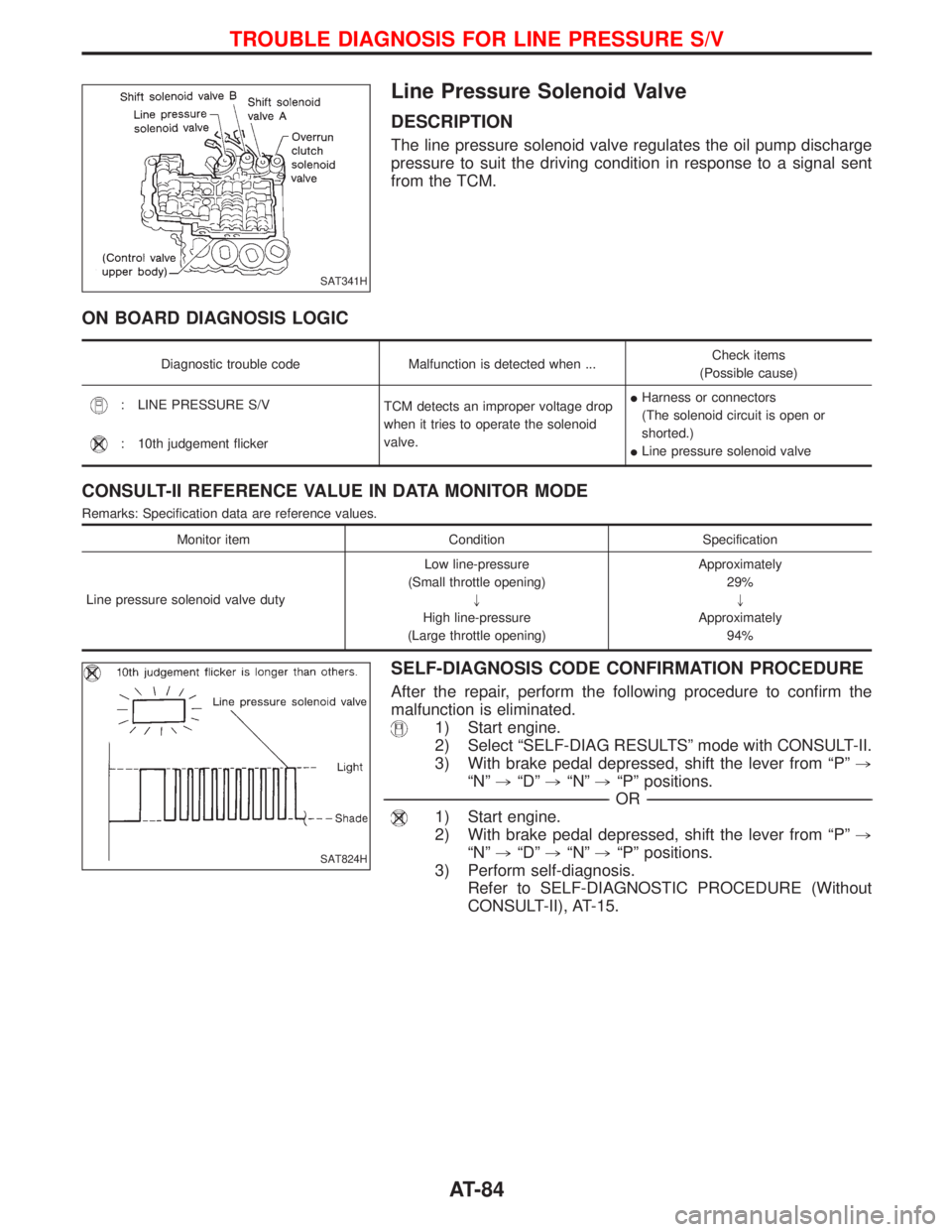
Line Pressure Solenoid Valve
DESCRIPTION
The line pressure solenoid valve regulates the oil pump discharge
pressure to suit the driving condition in response to a signal sent
from the TCM.
ON BOARD DIAGNOSIS LOGIC
Diagnostic trouble code Malfunction is detected when ...Check items
(Possible cause)
: LINE PRESSURE S/V
TCM detects an improper voltage drop
when it tries to operate the solenoid
valve.IHarness or connectors
(The solenoid circuit is open or
shorted.)
ILine pressure solenoid valve
: 10th judgement flicker
CONSULT-II REFERENCE VALUE IN DATA MONITOR MODE
Remarks: Specification data are reference values.
Monitor item Condition Specification
Line pressure solenoid valve dutyLow line-pressure
(Small throttle opening)
"
High line-pressure
(Large throttle opening)Approximately
29%
"
Approximately
94%
SELF-DIAGNOSIS CODE CONFIRMATION PROCEDURE
After the repair, perform the following procedure to confirm the
malfunction is eliminated.
1) Start engine.
2) Select ªSELF-DIAG RESULTSº mode with CONSULT-II.
3) With brake pedal depressed, shift the lever from ªPº,
ªNº,ªDº,ªNº,ªPº positions.
------------------------------------------------------------------------------------------------------------------------------------------------------------------------------------------------------------------------------------------------------------OR------------------------------------------------------------------------------------------------------------------------------------------------------------------------------------------------------------------------------------------------------------
1) Start engine.
2) With brake pedal depressed, shift the lever from ªPº,
ªNº,ªDº,ªNº,ªPº positions.
3) Perform self-diagnosis.
Refer to SELF-DIAGNOSTIC PROCEDURE (Without
CONSULT-II), AT-15.
SAT341H
SAT824H
TROUBLE DIAGNOSIS FOR LINE PRESSURE S/V
AT-84
Page 102 of 1767
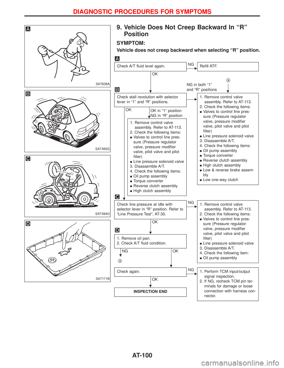
9. Vehicle Does Not Creep Backward In ªRº
Position
SYMPTOM:
Vehicle does not creep backward when selecting ªRº position.
Check A/T fluid level again.
OK
ENG
Refill ATF.
qA
NG in both ª1º
and ªRº positions
Check stall revolution with selector
lever in ª1º and ªRº positions.
OK
OK in ª1º position
NG in ªRº position
E1. Remove control valve
assembly. Refer to AT-113.
2. Check the following items:
IValves to control line pres-
sure (Pressure regulator
valve, pressure modifier
valve, pilot valve and pilot
filter)
ILine pressure solenoid valve
3. Disassemble A/T.
4. Check the following items:
IOil pump assembly
ITorque converter
IReverse clutch assembly
IHigh clutch assembly
ILow & reverse brake assem-
bly
ILow one-way clutch
1. Remove control valve
assembly. Refer to AT-113.
2. Check the following items:
IValves to control line pres-
sure (Pressure regulator
valve, pressure modifier
valve, pilot valve and pilot
filter)
ILine pressure solenoid valve
3. Disassemble A/T.
4. Check the following items:
IOil pump assembly
ITorque converter
IReverse clutch assembly
IHigh clutch assembly
Check line pressure at idle with
selector lever in ªRº position. Refer to
ªLine Pressure Testº, AT-30.
OK
ENG
1. Remove control valve
assembly. Refer to AT-113.
2. Check the following items:
IValves to control line pres-
sure (Pressure regulator
valve, pressure modifier
valve, pilot valve and pilot
filter)
ILine pressure solenoid valve
3. Disassemble A/T.
4. Check the following item:
IOil pump assembly
1. Remove oil pan.
2. Check A/T fluid condition.
NG OK
q
A
Check again.
OK
ENG
1. Perform TCM input/output
signal inspection.
2. If NG, recheck TCM pin ter-
minals for damage or loose
connection with harness con-
nector.
INSPECTION END
SAT638A
SAT493G
SAT494G
SAT171B
HH
H
H
H
H
H
H
DIAGNOSTIC PROCEDURES FOR SYMPTOMS
AT-100
Page 103 of 1767
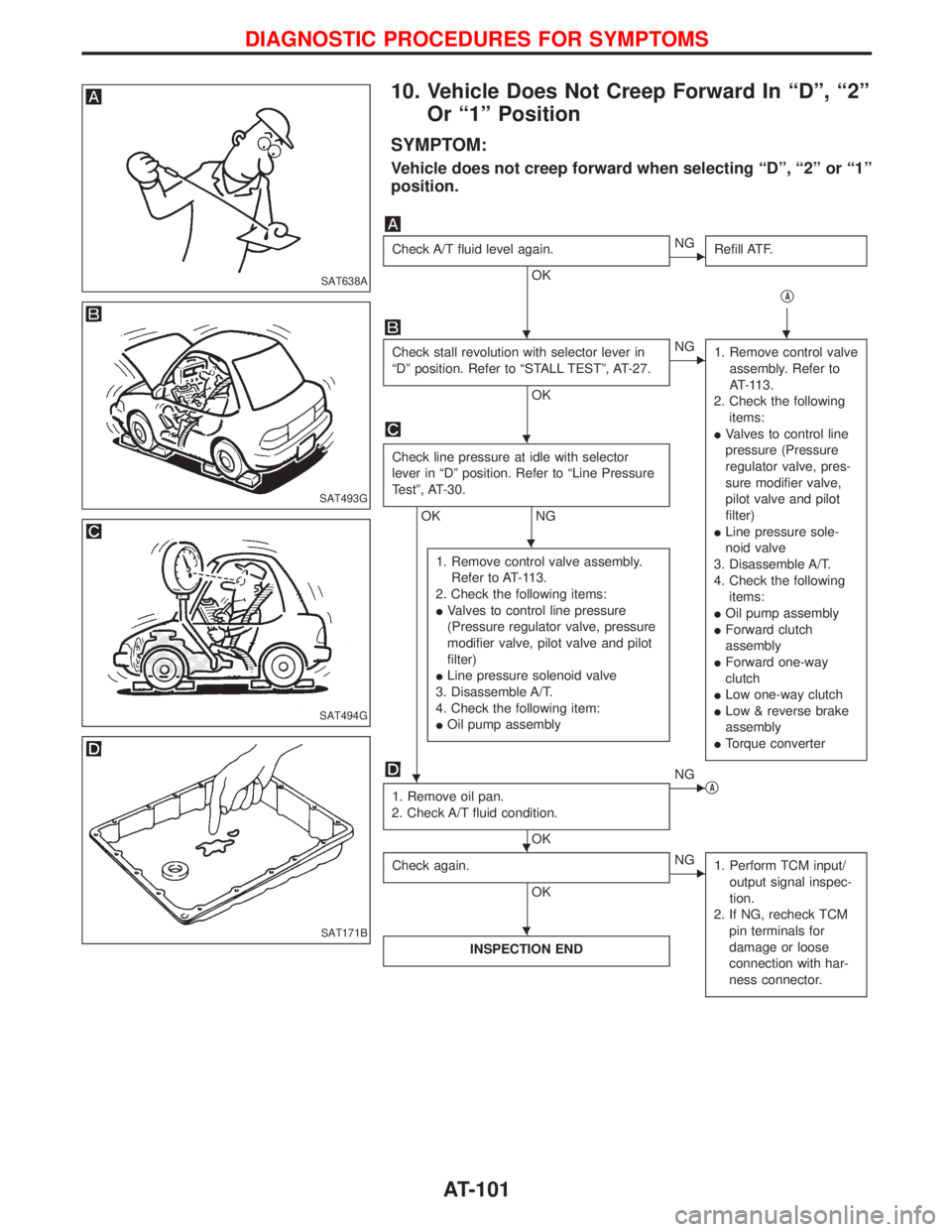
10. Vehicle Does Not Creep Forward In ªDº, ª2º
Or ª1º Position
SYMPTOM:
Vehicle does not creep forward when selecting ªDº, ª2º or ª1º
position.
Check A/T fluid level again.
OK
ENG
Refill ATF.
qA
Check stall revolution with selector lever in
ªDº position. Refer to ªSTALL TESTº, AT-27.
OK
ENG
1. Remove control valve
assembly. Refer to
AT-113.
2. Check the following
items:
IValves to control line
pressure (Pressure
regulator valve, pres-
sure modifier valve,
pilot valve and pilot
filter)
ILine pressure sole-
noid valve
3. Disassemble A/T.
4. Check the following
items:
IOil pump assembly
IForward clutch
assembly
IForward one-way
clutch
ILow one-way clutch
ILow & reverse brake
assembly
ITorque converter
Check line pressure at idle with selector
lever in ªDº position. Refer to ªLine Pressure
Testº, AT-30.
OK NG
1. Remove control valve assembly.
Refer to AT-113.
2. Check the following items:
IValves to control line pressure
(Pressure regulator valve, pressure
modifier valve, pilot valve and pilot
filter)
ILine pressure solenoid valve
3. Disassemble A/T.
4. Check the following item:
IOil pump assembly
1. Remove oil pan.
2. Check A/T fluid condition.
OK
ENG
qA
Check again.
OK
ENG
1. Perform TCM input/
output signal inspec-
tion.
2. If NG, recheck TCM
pin terminals for
damage or loose
connection with har-
ness connector.
INSPECTION END
SAT638A
SAT493G
SAT494G
SAT171B
HH
H
H
H
H H
H
DIAGNOSTIC PROCEDURES FOR SYMPTOMS
AT-101