oil NISSAN TERRANO 2004 Service Repair Manual
[x] Cancel search | Manufacturer: NISSAN, Model Year: 2004, Model line: TERRANO, Model: NISSAN TERRANO 2004Pages: 1833, PDF Size: 53.42 MB
Page 1495 of 1833
Oil Pressure Switch Check ...................................... 110
Wiring Diagram - CHIME - ...................................... 111
WIPER AND WASHER ................................................ 112
Wiring Diagram - WIPER - ...................................... 112
Wiring Diagram - WIP/R -........................................ 114
Installation ................................................................ 116
Washer Nozzle Adjustment ..................................... 117
Check Valve ............................................................. 117
Wiring Diagram - HLC - ........................................... 118
HORN, CIGARETTE LIGHTER AND CLOCK ............122
Wiring Diagram - HORN - .......................................122
Wiring Diagram - CIGAR -.......................................123
Wiring Diagram - CLOCK -......................................124
REAR WINDOW DEFOGGER AND DOOR
MIRROR DEFOGGER .................................................125
System Description ..................................................125
Wiring Diagram - DEF - ...........................................126
Trouble Diagnoses...................................................128
Filament Check ........................................................132
Filament Repair .......................................................133
AUDIO ........................................................................\
..134
System Description ..................................................134
Schematic ................................................................136
Wiring Diagram - AUDIO - .......................................138
Wiring Diagram - REMOTE -...................................145
Trouble Diagnoses...................................................147
Inspection.................................................................149
Location of Roof Mounted Antenna .........................150
HEATED SEAT ............................................................151
Wiring Diagram - HSEAT - ......................................151
SUNROOF ....................................................................153
Wiring Diagram - SROOF - .....................................153
DOOR MIRROR ...........................................................154
Wiring Diagram - MIRROR - ...................................154
POWER WINDOW .......................................................156
System Description ..................................................156
Schematic ................................................................158
Wiring Diagram - WINDOW - ..................................159
Trouble Diagnoses...................................................162
POWER DOOR LOCK .................................................163
System Description ..................................................163
Schematic ................................................................164
Wiring Diagram - D/LOCK -.....................................166
Trouble Diagnoses...................................................171
POWER DOOR LOCK - SUPER LOCK - ...................179
Component Parts Location ......................................179
System Description ..................................................180
Schematic ................................................................182 Wiring Diagram - S/LOCK - .....................................184
Trouble Diagnoses...................................................192
MULTI-REMOTE CONTROL SYSTEM .......................202
System Description ..................................................202
Schematic ................................................................204
Wiring Diagram - MULTI - .......................................205
Trouble Diagnoses...................................................213
ID Code Entry Procedure ........................................215
TIME CONTROL UNIT (TCU) .....................................216
System Description ..................................................216
Trouble Diagnosis ....................................................218
Schematic ................................................................220
NATS (Nissan Anti-Theft System) .............................222
System Description ..................................................222
System Composition ................................................223
Component Parts Location ......................................224
Wiring Diagram - NATS -.........................................225
CONSULT-II .............................................................229
Trouble Diagnoses...................................................231
How to Replace NATS IMMU ..................................242
THEFT WARNING SYSTEM .......................................243
Components Parts and Harness Connector
Location ...................................................................243
System Description ..................................................244
Theft Warning System/Schematic ...........................247
Wiring Diagram - THEFT -.......................................248
Trouble Diagnoses...................................................264
LOCATION OF ELECTRICAL UNITS .........................275
Engine Compartment ...............................................275
Passenger Compartment/LHD Models ....................276
Passenger Compartment/RHD Models ...................278
HARNESS LAYOUT ....................................................280
How to Read Harness Layout .................................280
Outline......................................................................281
Main Harness...........................................................282
EFC Harness ...........................................................298
Engine Harness .......................................................310
Body Harness ..........................................................312
Chassis Harness......................................................320
Room Lamp Harness...............................................321
Tailgate Harness ......................................................322
Door Harness (LH side)...........................................323
Door Harness (RH side) ..........................................324
BULB SPECIFICATIONS ............................................325
Headlamps ...............................................................325
Exterior Lamps.........................................................325
Interior Lamps ..........................................................325
WIRING DIAGRAM CODES (CELL CODES) .............326
CONTENTS(Cont'd)
EL-2
http://vnx.su/
Page 1540 of 1833
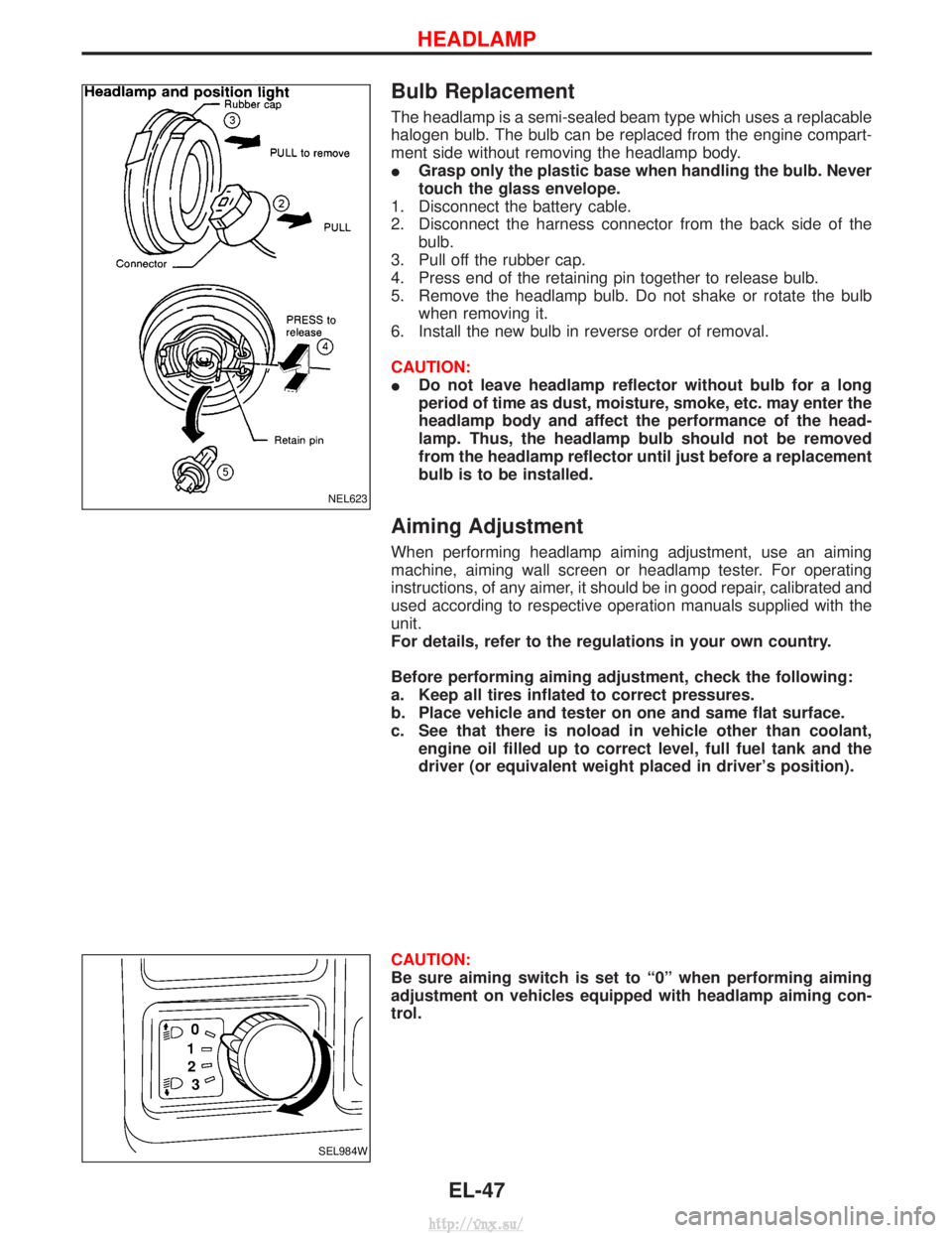
Bulb Replacement
The headlamp is a semi-sealed beam type which uses a replacable
halogen bulb. The bulb can be replaced from the engine compart-
ment side without removing the headlamp body.
IGrasp only the plastic base when handling the bulb. Never
touch the glass envelope.
1. Disconnect the battery cable.
2. Disconnect the harness connector from the back side of the bulb.
3. Pull off the rubber cap.
4. Press end of the retaining pin together to release bulb.
5. Remove the headlamp bulb. Do not shake or rotate the bulb when removing it.
6. Install the new bulb in reverse order of removal.
CAUTION:
I Do not leave headlamp reflector without bulb for a long
period of time as dust, moisture, smoke, etc. may enter the
headlamp body and affect the performance of the head-
lamp. Thus, the headlamp bulb should not be removed
from the headlamp reflector until just before a replacement
bulb is to be installed.
Aiming Adjustment
When performing headlamp aiming adjustment, use an aiming
machine, aiming wall screen or headlamp tester. For operating
instructions, of any aimer, it should be in good repair, calibrated and
used according to respective operation manuals supplied with the
unit.
For details, refer to the regulations in your own country.
Before performing aiming adjustment, check the following:
a. Keep all tires inflated to correct pressures.
b. Place vehicle and tester on one and same flat surface.
c. See that there is noload in vehicle other than coolant,
engine oil filled up to correct level, full fuel tank and the
driver (or equivalent weight placed in driver's position).
CAUTION:
Be sure aiming switch is set to ª0º when performing aiming
adjustment on vehicles equipped with headlamp aiming con-
trol.
NEL623
SEL984W
HEADLAMP
EL-47
http://vnx.su/
Page 1550 of 1833
Front Fog Lamp Aiming Adjustment
When performing fog lamp aiming adjustment, use an aiming
machine, aiming wall screen or headlamp tester. The aimer should
be in good operational condition, calibrated and used according to
the relevant operation manuals supplied with the unit.
If an aimer is not available, aiming adjustment can be done as fol-
lows:
For details, refer to the regulations in your own country.
CAUTION:
IKeep all tires inflated to correct pressures.
I Place vehicle and tester on one and the same flat surface.
I Ensure that there is no-load in the vehicle other than
coolant, engine oil (filled up to correct level), full fuel tank
and the driver (or equivalent weight placed in driver's posi-
tion).
For details of front fog lamp aiming adjustment, refer to ªAiming
Adjustmentº, EL-47.
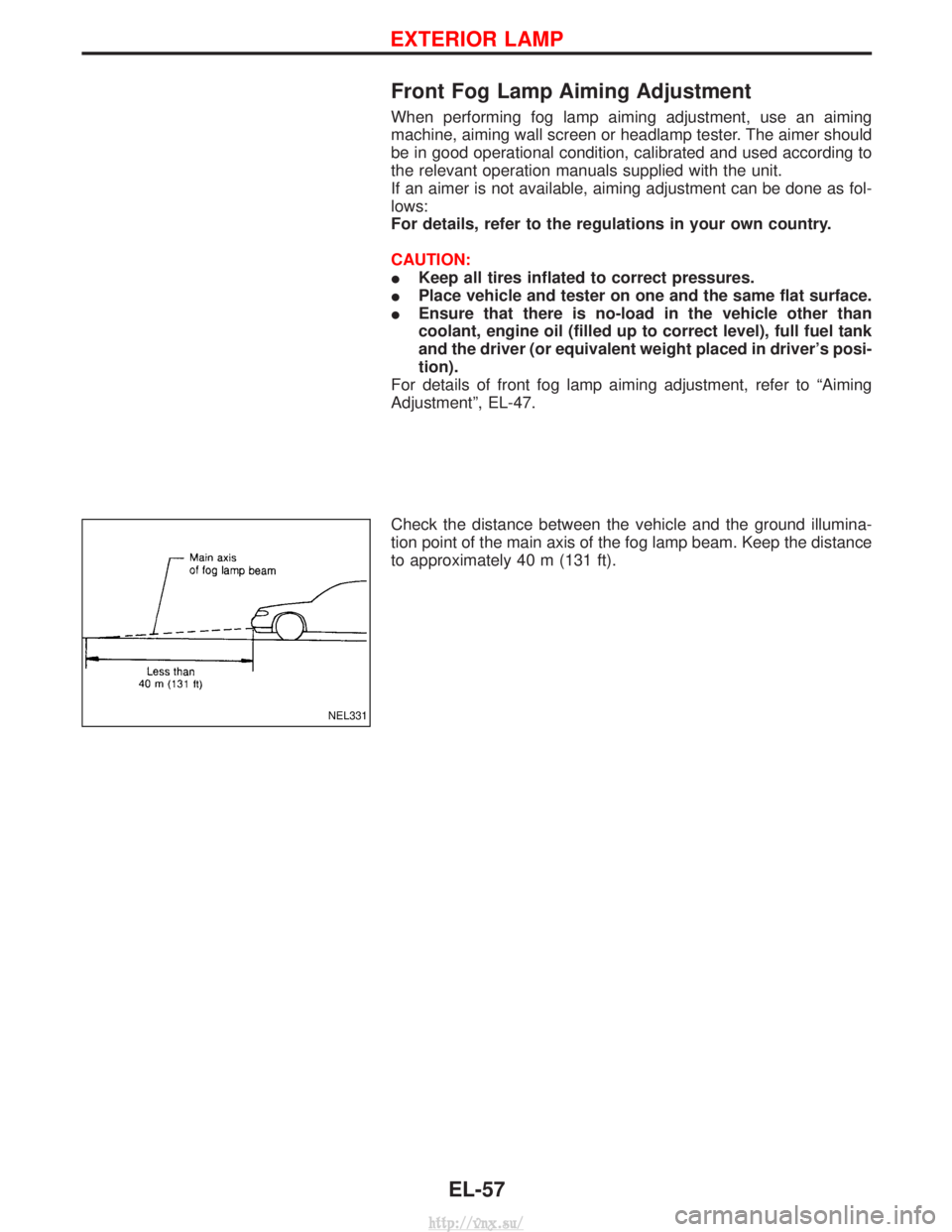
Check the distance between the vehicle and the ground illumina-
tion point of the main axis of the fog lamp beam. Keep the distance
to approximately 40 m (131 ft).
NEL331
EXTERIOR LAMP
EL-57
http://vnx.su/
Page 1603 of 1833
Electrical Components Inspection
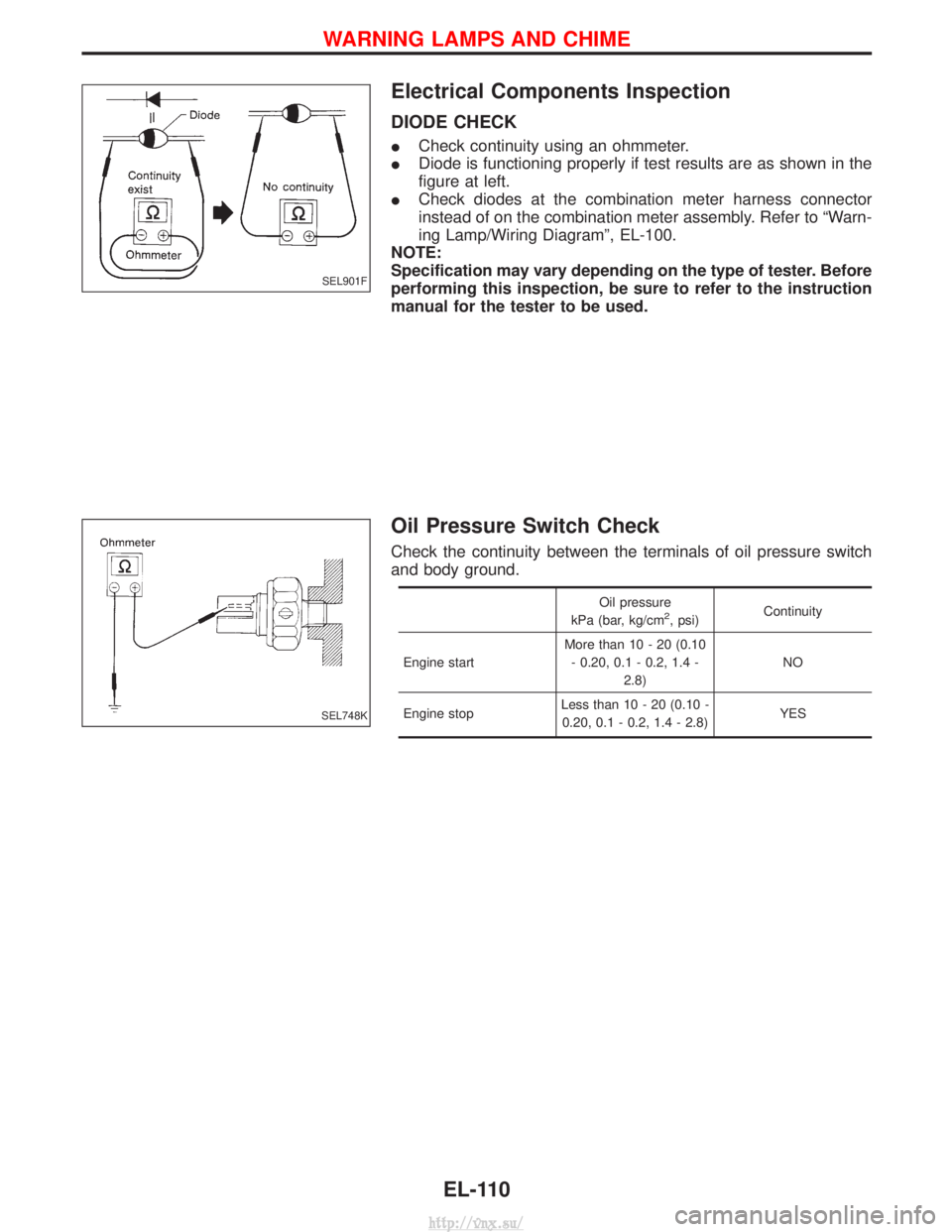
DIODE CHECK
ICheck continuity using an ohmmeter.
I Diode is functioning properly if test results are as shown in the
figure at left.
I Check diodes at the combination meter harness connector
instead of on the combination meter assembly. Refer to ªWarn-
ing Lamp/Wiring Diagramº, EL-100.
NOTE:
Specification may vary depending on the type of tester. Before
performing this inspection, be sure to refer to the instruction
manual for the tester to be used.
Oil Pressure Switch Check
Check the continuity between the terminals of oil pressure switch
and body ground.
Oil pressure
kPa (bar, kg/cm2, psi) Continuity
Engine start More than 10 - 20 (0.10
- 0.20, 0.1 - 0.2, 1.4 - 2.8) NO
Engine stop Less than 10 - 20 (0.10 -
0.20, 0.1 - 0.2, 1.4 - 2.8) YES
SEL901F
SEL748K
WARNING LAMPS AND CHIME
EL-110
http://vnx.su/
Page 1618 of 1833
System Description
The rear window defogger system is controlled by the time control unit. The rear window defogger operates
only for approximately 15 minutes.
Rear window defogger switch is built into the A/C control panel.
Power is supplied at all times
Ithrough 10A fuse [No. 5, located in the fuse block (J/B)]
I to time control unit terminal U09.
With the ignition switch in the ON or START position, power is supplied
I through 10A fuse [No. 26, located in the fuse block (J/B)]
I to time control unit terminal U01
I to rear window defogger relay coil power side.
Ground is supplied
I to time control unit terminal U16
I through terminal MM2 of fuse block (J/B)
I through body grounds F36, F47 (LHD models) or M33, M754 (RHD models)
I to terminal 5 of A/C control panel (rear window defogger switch)
I through body grounds M33 and M754.
When the rear defogger switch is turned ON, ground is supplied
I through terminals 3 and 5 of A/C control panel (rear defogger switch)
I through terminal M19 of fuse block (J/B)
I to time control unit terminal U03.
Terminal U13 of time control unit then supplies ground to the rear window defogger relay coil ground side.
With power and ground supplied, the rear window defogger relay is energized.
Power is supplied
I through 15A fuse [No. 14 and No. 15, located in the fuse block (J/B)]
I to the rear window defogger terminal 1
I through 10A fuse [No. 1, located in the fuse block (J/B)]
I to door mirror LH/RH (defogger) terminal 3.
Ground is supplied
I to rear window defogger terminal 2
I to door mirror LH/RH terminal 2
I through body grounds B10 and B18.
With power and ground supplied, the rear window defogger filaments heat and defog the rear window.
When the system is activated, the rear window defogger indicator illuminates in the rear window defogger
switch.
REAR WINDOW DEFOGGER AND DOOR MIRROR DEFOGGER
EL-125
http://vnx.su/
Page 1625 of 1833
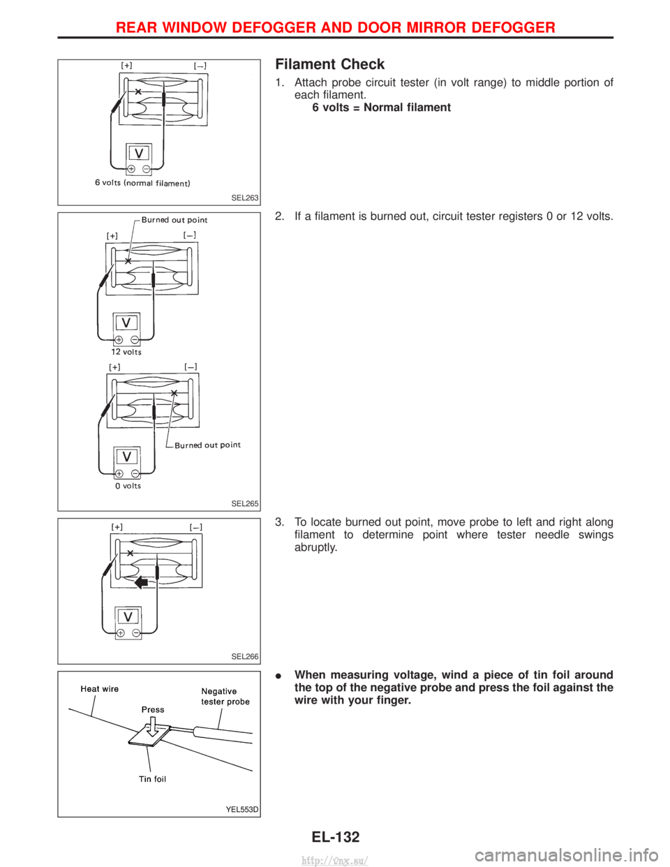
Filament Check
1. Attach probe circuit tester (in volt range) to middle portion ofeach filament.6 volts = Normal filament
2. If a filament is burned out, circuit tester registers 0 or 12 volts.
3. To locate burned out point, move probe to left and right along filament to determine point where tester needle swings
abruptly.
I When measuring voltage, wind a piece of tin foil around
the top of the negative probe and press the foil against the
wire with your finger.
SEL263
SEL265
SEL266
YEL553D
REAR WINDOW DEFOGGER AND DOOR MIRROR DEFOGGER
EL-132
http://vnx.su/
Page 1640 of 1833
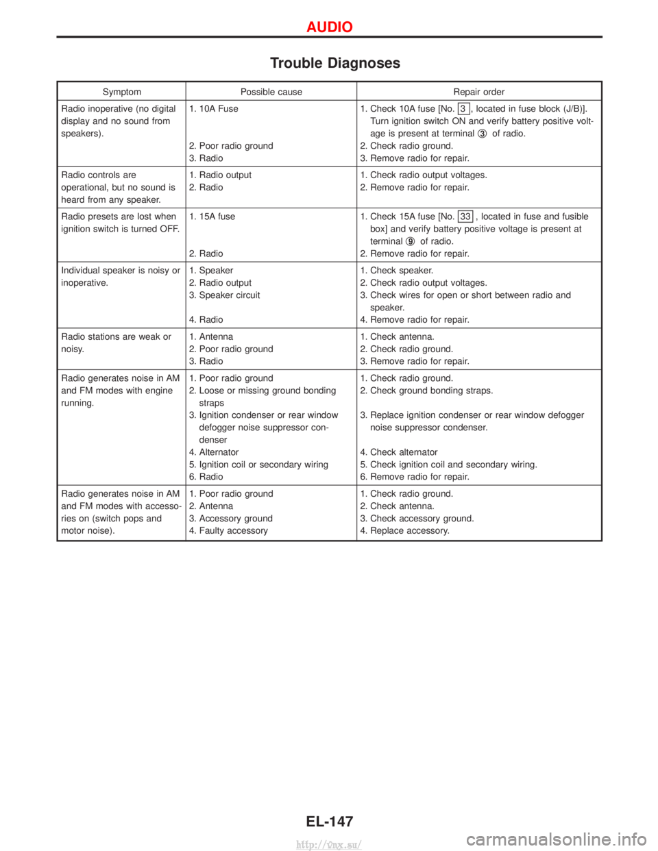
Trouble Diagnoses
SymptomPossible cause Repair order
Radio inoperative (no digital
display and no sound from
speakers). 1. 10A Fuse
2. Poor radio ground
3. Radio 1. Check 10A fuse [No.
3 , located in fuse block (J/B)].
Turn ignition switch ON and verify battery positive volt-
age is present at terminal q
3of radio.
2. Check radio ground.
3. Remove radio for repair.
Radio controls are
operational, but no sound is
heard from any speaker. 1. Radio output
2. Radio
1. Check radio output voltages.
2. Remove radio for repair.
Radio presets are lost when
ignition switch is turned OFF. 1. 15A fuse
2. Radio 1. Check 15A fuse [No.
33 , located in fuse and fusible
box] and verify battery positive voltage is present at
terminal q
9of radio.
2. Remove radio for repair.
Individual speaker is noisy or
inoperative. 1. Speaker
2. Radio output
3. Speaker circuit
4. Radio 1. Check speaker.
2. Check radio output voltages.
3. Check wires for open or short between radio and
speaker.
4. Remove radio for repair.
Radio stations are weak or
noisy. 1. Antenna
2. Poor radio ground
3. Radio 1. Check antenna.
2. Check radio ground.
3. Remove radio for repair.
Radio generates noise in AM
and FM modes with engine
running. 1. Poor radio ground
2. Loose or missing ground bonding
straps
3. Ignition condenser or rear window defogger noise suppressor con-
denser
4. Alternator
5. Ignition coil or secondary wiring
6. Radio 1. Check radio ground.
2. Check ground bonding straps.
3. Replace ignition condenser or rear window defogger
noise suppressor condenser.
4. Check alternator
5. Check ignition coil and secondary wiring.
6. Remove radio for repair.
Radio generates noise in AM
and FM modes with accesso-
ries on (switch pops and
motor noise). 1. Poor radio ground
2. Antenna
3. Accessory ground
4. Faulty accessory 1. Check radio ground.
2. Check antenna.
3. Check accessory ground.
4. Replace accessory.
AUDIO
EL-147
http://vnx.su/
Page 1641 of 1833
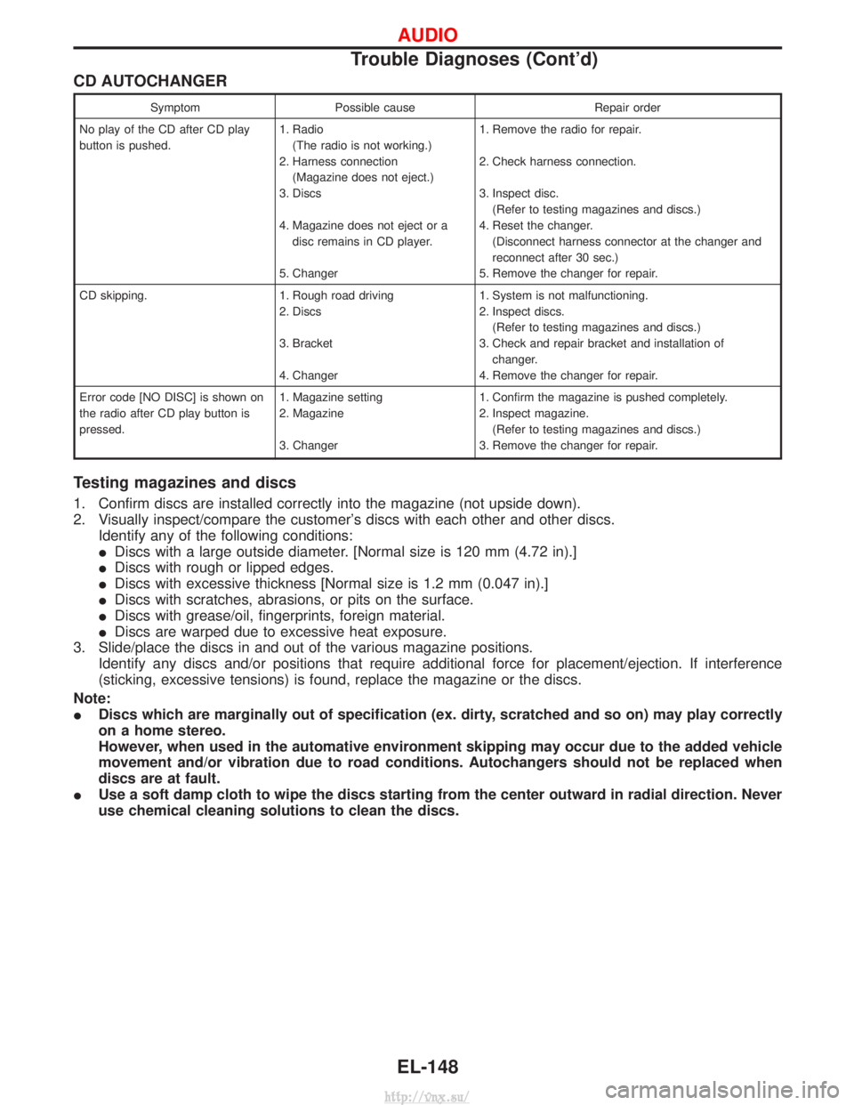
CD AUTOCHANGER
SymptomPossible cause Repair order
No play of the CD after CD play
button is pushed. 1. Radio
(The radio is not working.)
2. Harness connection (Magazine does not eject.)
3. Discs
4. Magazine does not eject or a disc remains in CD player.
5. Changer 1. Remove the radio for repair.
2. Check harness connection.
3. Inspect disc.
(Refer to testing magazines and discs.)
4. Reset the changer. (Disconnect harness connector at the changer and
reconnect after 30 sec.)
5. Remove the changer for repair.
CD skipping. 1. Rough road driving 2. Discs
3. Bracket
4. Changer1. System is not malfunctioning.
2. Inspect discs.
(Refer to testing magazines and discs.)
3. Check and repair bracket and installation of changer.
4. Remove the changer for repair.
Error code [NO DISC] is shown on
the radio after CD play button is
pressed. 1. Magazine setting
2. Magazine
3. Changer1. Confirm the magazine is pushed completely.
2. Inspect magazine.
(Refer to testing magazines and discs.)
3. Remove the changer for repair.
Testing magazines and discs
1. Confirm discs are installed correctly into the magazine (not upside down).
2. Visually inspect/compare the customer's discs with each other and other discs. Identify any of the following conditions:
IDiscs with a large outside diameter. [Normal size is 120 mm (4.72 in).]
I Discs with rough or lipped edges.
I Discs with excessive thickness [Normal size is 1.2 mm (0.047 in).]
I Discs with scratches, abrasions, or pits on the surface.
I Discs with grease/oil, fingerprints, foreign material.
I Discs are warped due to excessive heat exposure.
3. Slide/place the discs in and out of the various magazine positions. Identify any discs and/or positions that require additional force for placement/ejection. If interference
(sticking, excessive tensions) is found, replace the magazine or the discs.
Note:
I Discs which are marginally out of specification (ex. dirty, scratched and so on) may play correctly
on a home stereo.
However, when used in the automative environment skipping may occur due to the added vehicle
movement and/or vibration due to road conditions. Autochangers should not be replaced when
discs are at fault.
I Use a soft damp cloth to wipe the discs starting from the center outward in radial direction. Never
use chemical cleaning solutions to clean the discs.
AUDIO
Trouble Diagnoses (Cont'd)
EL-148
http://vnx.su/
Page 1819 of 1833
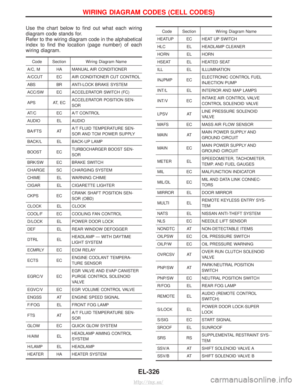
Use the chart below to find out what each wiring
diagram code stands for.
Refer to the wiring diagram code in the alphabetical
index to find the location (page number) of each
wiring diagram.
Code Section Wiring Diagram Name
A/C, M HA MANUAL AIR CONDITIONER
A/CCUT EC AIR CONDITIONER CUT CONTROL
ABS BR ANTI-LOCK BRAKE SYSTEM
ACC/SW EC ACCELERATOR SWITCH (FC)
APS AT, EC ACCELERATOR POSITION SEN-
SOR
AT/C EC A/T CONTROL
AUDIO EL AUDIO
BA/FTS AT A/T FLUID TEMPERATURE SEN-
SOR AND TCM POWER SUPPLY
BACK/L EL BACK-UP LAMP
BOOST EC TURBOCHARGER BOOST SEN-
SOR
BRK/SW EC BRAKE SWITCH
CHARGE SC CHARGING SYSTEM
CHIME EL WARNING CHIME
CIGAR EL CIGARETTE LIGHTER
CKPS EC CRANK SHAFT POSITION SEN-
SOR (OBD)
CLOCK EL CLOCK
COOL/F EC COOLING FAN CONTROL
D/LOCK EL POWER DOOR LOCK
DEF EL REAR WINDOW DEFOGGER
DTRL EL HEADLAMP Ð WITH DAYTIME
LIGHT SYSTEM
ECMRLY EC ECM RELAY
ECTS EC ENGINE COOLANT TEMPERA-
TURE SENSOR
EGRC/V EC EGR VALVE AND EVAP CANISTER
PURGE CONTROL SOLENOID
VA LV E
EGVC/V EC EGR VOLUME CONTROL VALVE
ENGSS AT ENGINE SPEED SIGNAL
F/FOG EL FRONT FOG LAMP
FTS AT A/T FLUID TEMPERATURE SEN-
SOR
GLOW EC QUICK GLOW SYSTEM
H/AIM EL HEADLAMP AIMING CONTROL
SYSTEM
H/LAMP EL HEADLAMP
HEATER HA HEATER SYSTEM
Code Section Wiring Diagram Name
HEATUP EC HEAT UP SWITCH
HLC EL HEADLAMP CLEANER
HORN EL HORN
HSEAT EL HEATED SEAT
ILL EL ILLUMINATION
INJPMP EC ELECTRONIC CONTROL FUEL
INJECTION PUMP
INT/L EL INTERIOR AND MAP LAMPS
INT/V EC INTAKE AIR CONTROL VALVE
CONTROL SOLENOID VALVE
LPSV AT LINE PRESSURE SOLENOID
VA LV E
MAFS EC MASS AIR FLOW SENSOR
MAIN AT MAIN POWER SUPPLY AND
GROUND CIRCUIT
MAIN EC MAIN POWER SUPPLY AND
GROUND CIRCUIT
METER EL SPEEDOMETER, TACHOMETER,
TEMP. AND FUEL GAUGES
MIL EC MALFUNCTION INDICATOR
MIL/DL EC MIL AND DATA LINK CONNEC-
TORS
MIRROR EL DOOR MIRROR
MULTI EL REMOTE KEYLESS ENTRY SYS-
TEM
NATS EL NISSAN ANTI-THEFT SYSTEM
NLS EC NEEDLE LIFT SENSOR
NONDTC AT NON-DETECTABLE ITEMS
OILPSW EC OIL PRESSURE SWITCH
OILP/W EC OIL PRESSURE WARNING
OVRCSV AT OVER RUN CLUTCH SOLENOID
VA LV E
PNP/SW AT PARK/NEUTRAL POSITION
SWITCH
PNP/SW EC NEUTRAL POSITION SWITCH
R/FOG EL REAR FOG LAMP
REMOTE EL AUDIO (REMOTE CONTROL
SWITCH)
S/LOCK EL POWER DOOR LOCK-SUPER
LOCK
S/SIG EC START SIGNAL
SROOF EL SUNROOF
SRS RS SUPPLEMENTAL RESTRAINT SYS-
TEM
SSV/A AT SHIFT SOLENOID VALVE A
SSV/B AT SHIFT SOLENOID VALVE B
WIRING DIAGRAM CODES (CELL CODES)
EL-326
http://vnx.su/
Page 1828 of 1833
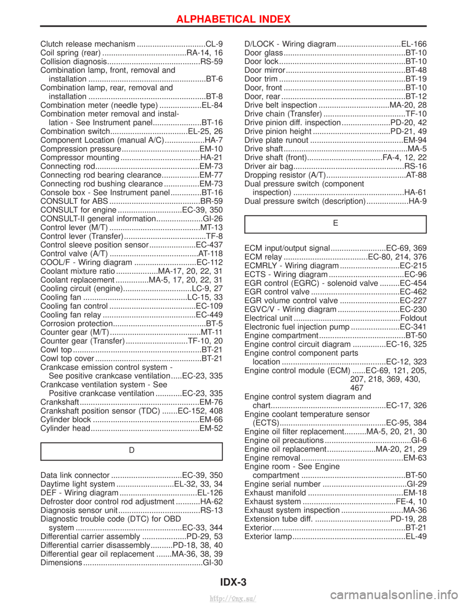
Clutch release mechanism ...............................CL-9
Coil spring (rear) ......................................RA-14, 16
Collision diagnosis..........................................RS-59
Combination lamp, front, removal andinstallation .....................................................BT-6
Combination lamp, rear, removal and installation .....................................................BT-8
Combination meter (needle type) ...................EL-84
Combination meter removal and instal- lation - See Instrument panel......................BT-16
Combination switch...................................EL-25, 26
Component Location (manual A/C) ..................HA-7
Compression pressure ...................................EM-10
Compressor mounting ....................................HA-21
Connecting rod...............................................EM-73
Connecting rod bearing clearance.................EM-77
Connecting rod bushing clearance ................EM-73
Console box - See Instrument panel ..............BT-16
CONSULT for ABS .........................................BR-59
CONSULT for engine .............................EC-39, 350
CONSULT-II general information.....................GI-26
Control lever (M/T) .........................................MT-13
Control lever (Transfer) .....................................TF-8
Control sleeve position sensor .....................EC-437
Control valve (A/T) ........................................AT-118
COOL/F - Wiring diagram ............................EC-112
Coolant mixture ratio ...................MA-17, 20, 22, 31
Coolant replacement ...............MA-5, 17, 20, 22, 31
Cooling circuit (engine)...............................LC-9, 27
Cooling fan ...............................................LC-15, 33
Cooling fan control .......................................EC-109
Cooling fan relay ..........................................EC-449
Corrosion protection..........................................BT-5
Counter gear (M/T) .........................................MT-11
Counter gear (Transfer) ............................TF-10, 20
Cowl top ..........................................................BT-21
Cowl top cover ................................................BT-21
Crankcase emission control system - See positive crankcase ventilation .....EC-23, 335
Crankcase ventilation system - See Positive crankcase ventilation ............EC-23, 335
Crankshaft ......................................................EM-76
Crankshaft position sensor (TDC) .......EC-152, 408
Cylinder block ................................................EM-66
Cylinder head .................................................EM-52
D
Data link connector ................................EC-39, 350
Daytime light system ..........................EL-32, 33, 34
DEF - Wiring diagram ...................................EL-126
Defroster door control rod adjustment ...........HA-62
Diagnosis sensor unit .....................................RS-13
Diagnostic trouble code (DTC) for OBDsystem ................................................EC-33, 344
Differential carrier assembly ....................PD-29, 53
Differential carrier disassembly..........PD-18, 38, 40
Differential gear oil replacement .......MA-36, 38, 39
Dimensions ......................................................GI-30 D/LOCK - Wiring diagram .............................EL-166
Door glass .......................................................BT-10
Door lock .........................................................BT-10
Door mirror ......................................................BT-48
Door trim .........................................................BT-19
Door, front .......................................................BT-10
Door, rear ........................................................BT-12
Drive belt inspection ................................MA-20, 28
Drive chain (Transfer) .....................................TF-10
Drive pinion diff. inspection ......................PD-20, 42
Drive pinion height ...................................PD-21, 49
Drive plate runout ..........................................EM-94
Drive shaft ........................................................MA-5
Drive shaft (front)..................................FA-4, 12, 22
Driver air bag..................................................RS-16
Dropping resistor (A/T)....................................AT-88
Dual pressure switch (component
inspection) ..................................................HA-61
Dual pressure switch (description) ...................HA-9
E
ECM input/output signal .........................EC-69, 369
ECM relay ......................................EC-80, 214, 376
ECMRLY - Wiring diagram ...........................EC-215
ECTS - Wiring diagram ..................................EC-96
EGR control (EGRC) - solenoid valve .........EC-454
EGR control valve ........................................EC-462
EGR volume control valve ...........................EC-227
EGVC/V - Wiring diagram ............................EC-230
Electrical unit ................................................Foldout
Electronic fuel injection pump ......................EC-341
Engine compartment .......................................BT-50
Engine control circuit diagram ...............EC-16, 325
Engine control component partslocation ...............................................EC-12, 323
Engine control module (ECM) ......EC-69, 121, 205, 207, 218, 369, 430,
467
Engine control system diagram and chart....................................................EC-17, 326
Engine coolant temperature sensor (ECTS)................................................EC-95, 384
Engine oil filter replacement..........MA-5, 20, 21, 30
Engine oil precautions .......................................GI-6
Engine oil replacement ......................MA-20, 21, 29
Engine removal ..............................................EM-63
Engine room - See Engine compartment ...............................................BT-50
Engine serial number ......................................GI-29
Exhaust manifold ...........................................EM-18
Exhaust system ..........................................FE-4, 10
Exhaust system inspection ............................MA-36
Extension tube diff. ..................................PD-19, 28
Exterior ............................................................BT-21
Exterior lamp ...................................................EL-49
ALPHABETICAL INDEX
IDX-3
http://vnx.su/