fuel pump NISSAN TERRANO 2004 Service Owner's Guide
[x] Cancel search | Manufacturer: NISSAN, Model Year: 2004, Model line: TERRANO, Model: NISSAN TERRANO 2004Pages: 1833, PDF Size: 53.42 MB
Page 316 of 1833
![NISSAN TERRANO 2004 Service Owners Guide Monitored item
[Unit]ECM
input
signals Main
signals Description Remarks
FUEL TEMP SEN
[ÉC] or [ÉF] qqI
The fuel temperature (sent from elec-
tronic control fuel injection pump) is dis-
played.
ACCEL](/img/5/57394/w960_57394-315.png "NISSAN TERRANO 2004 Service Owners Guide Monitored item
[Unit]ECM
input
signals Main
signals Description Remarks
FUEL TEMP SEN
[ÉC] or [ÉF] qqI
The fuel temperature (sent from elec-
tronic control fuel injection pump) is dis-
played.
ACCEL")
Monitored item
[Unit]ECM
input
signals Main
signals Description Remarks
FUEL TEMP SEN
[ÉC] or [ÉF] qqI
The fuel temperature (sent from elec-
tronic control fuel injection pump) is dis-
played.
ACCEL POS SEN [V] qqI
The accelerator position sensor signal
voltage is displayed.
FULL ACCEL SW
[ON/OFF] qqI
Indicates [ON/OFF] condition from the
accelerator position switch signal.
ACCEL SW (FC)
[OPEN/CLOSE] qqI
Indicates [OPEN/CLOSE] condition from
the accelerator switch (FC) signal.
OFF ACCEL SW
[ON/OFF] qqI
Indicates [ON/OFF] condition from the
accelerator position switch signal.
SPILL/V [ÉCA] qI
The control position of spill valve (sent
from electronic control fuel injection
pump) is displayed.
BATTERY VOLT [V] qqI
The power supply voltage of ECM is dis-
played.
P/N POSI SW
[ON/OFF] qqI
Indicates [ON/OFF] condition from the
park/neutral position switch signal.
START SIGNAL
[ON/OFF] qqI
Indicates [ON/OFF] condition from the
starter signal. I
After starting the engine, [OFF] is dis-
played regardless of the starter signal.
AIR COND SIG
[ON/OFF] qqI
Indicates [ON/OFF] condition of the air
conditioner switch as determined by the
air conditioner signal.
BRAKE SW [ON/OFF] qqI
Indicates [ON/OFF] condition from the
stop lamp switch signal.
IGN SW
[ON/OFF] qqI
Indicates [ON/OFF] condition from igni-
tion switch signal.
WARM UP SW
[ON/OFF] qI
Indicates [ON/OFF] condition from the
heat up switch signal.
MAS AIR/FL SE [V] qqI
The signal voltage of the mass air flow
sensor is displayed. I
When the engine is stopped, a certain
value is indicated.
DECELER F/CUT
[ON/OFF] qI
The [ON/OFF] condition from decelera-
tion fuel cut signal (sent from electronic
control fuel injection pump) is displayed.
INJ TIMG C/V [%] qI
The duty ratio of fuel injection timing
control valve (sent from electronic control
fuel injection pump) is displayed.
AIR COND RLY
[ON/OFF] qI
Indicates the control condition of the air
conditioner relay (determined by ECM
according to the input signals).
GLOW RLY [ON/OFF] qI
The glow relay control condition (deter-
mined by ECM according to the input
signal) is displayed.
COOLING FAN
[ON/OFF] qI
Indicates the control condition of the
cooling fans (determined by ECM
according to the input signal).
I ON ... Operates.
OFF ... Stopped.
ON BOARD DIAGNOSTIC SYSTEM DESCRIPTIONZD30DDTi
CONSULT-II (Cont'd)
EC-41
http://vnx.su/
Page 318 of 1833
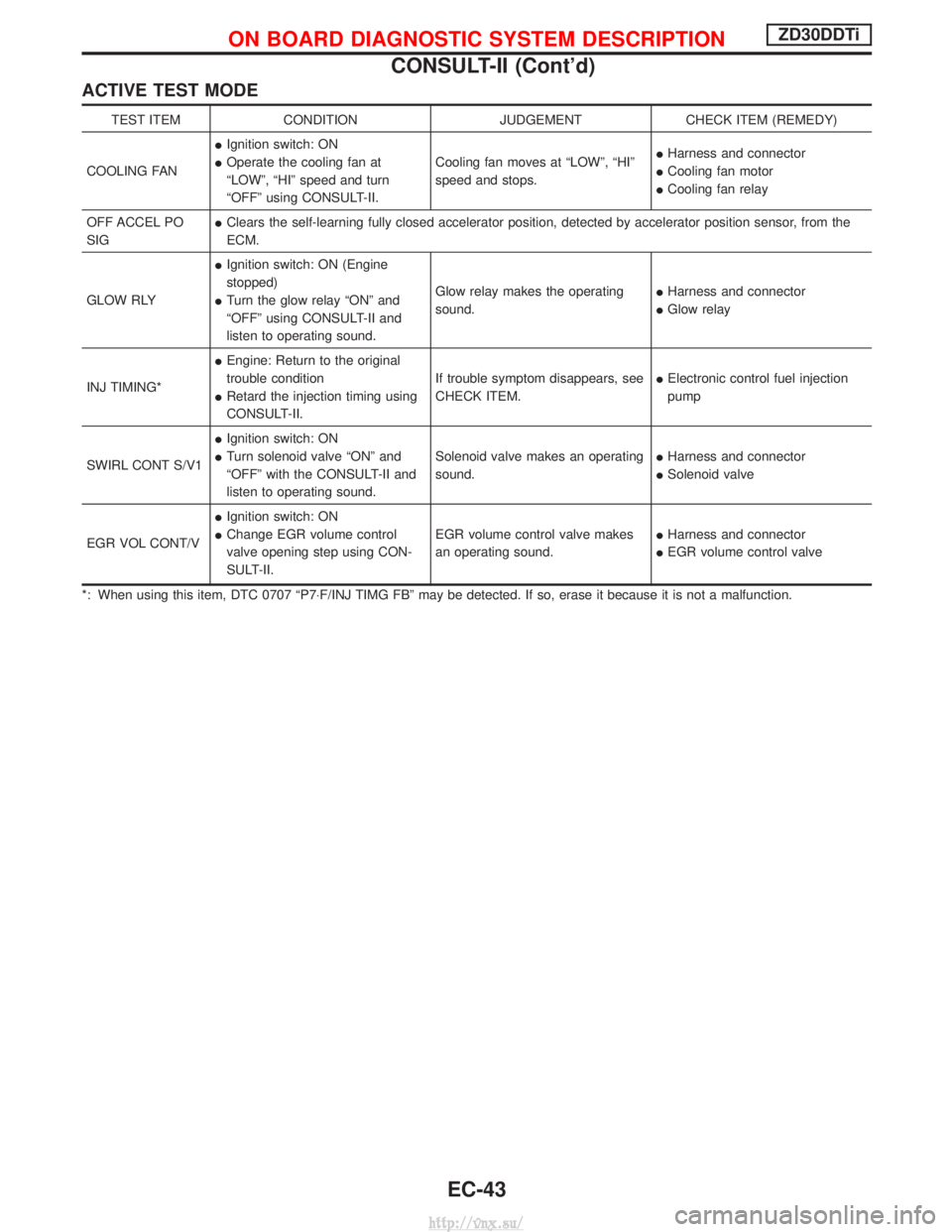
ACTIVE TEST MODE
TEST ITEMCONDITION JUDGEMENTCHECK ITEM (REMEDY)
COOLING FAN I
Ignition switch: ON
I Operate the cooling fan at
ªLOWº, ªHIº speed and turn
ªOFFº using CONSULT-II. Cooling fan moves at ªLOWº, ªHIº
speed and stops.
I
Harness and connector
I Cooling fan motor
I Cooling fan relay
OFF ACCEL PO
SIG I
Clears the self-learning fully closed accelerator position, detected by accelerator position sensor, from the
ECM.
GLOW RLY I
Ignition switch: ON (Engine
stopped)
I Turn the glow relay ªONº and
ªOFFº using CONSULT-II and
listen to operating sound. Glow relay makes the operating
sound.
I
Harness and connector
I Glow relay
INJ TIMING* I
Engine: Return to the original
trouble condition
I Retard the injection timing using
CONSULT-II. If trouble symptom disappears, see
CHECK ITEM.
I
Electronic control fuel injection
pump
SWIRL CONT S/V1 I
Ignition switch: ON
I Turn solenoid valve ªONº and
ªOFFº with the CONSULT-II and
listen to operating sound. Solenoid valve makes an operating
sound.
I
Harness and connector
I Solenoid valve
EGR VOL CONT/V I
Ignition switch: ON
I Change EGR volume control
valve opening step using CON-
SULT-II. EGR volume control valve makes
an operating sound.
I
Harness and connector
I EGR volume control valve
*: When using this item, DTC 0707 ªP7 ×F/INJ TIMG FBº may be detected. If so, erase it because it is not a malfunction.
ON BOARD DIAGNOSTIC SYSTEM DESCRIPTIONZD30DDTi
CONSULT-II (Cont'd)
EC-43
http://vnx.su/
Page 321 of 1833
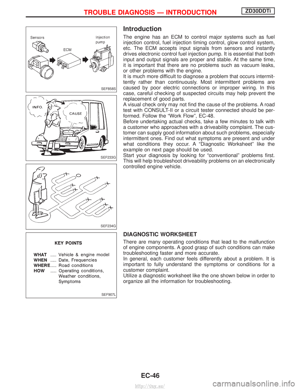
Introduction
The engine has an ECM to control major systems such as fuel
injection control, fuel injection timing control, glow control system,
etc. The ECM accepts input signals from sensors and instantly
drives electronic control fuel injection pump. It is essential that both
input and output signals are proper and stable. At the same time,
it is important that there are no problems such as vacuum leaks,
or other problems with the engine.
It is much more difficult to diagnose a problem that occurs intermit-
tently rather than continuously. Most intermittent problems are
caused by poor electric connections or improper wiring. In this
case, careful checking of suspected circuits may help prevent the
replacement of good parts.
A visual check only may not find the cause of the problems. A road
test with CONSULT-II or a circuit tester connected should be per-
formed. Follow the ªWork Flowº, EC-48.
Before undertaking actual checks, take a few minutes to talk with
a customer who approaches with a driveability complaint. The cus-
tomer can supply good information about such problems, especially
intermittent ones. Find out what symptoms are present and under
what conditions they occur. A ªDiagnostic Worksheetº like the
example on next page should be used.
Start your diagnosis by looking for ªconventionalº problems first.
This will help troubleshoot driveability problems on an electronically
controlled engine vehicle.
DIAGNOSTIC WORKSHEET
There are many operating conditions that lead to the malfunction
of engine components. A good grasp of such conditions can make
troubleshooting faster and more accurate.
In general, each customer feels differently about a problem. It is
important to fully understand the symptoms or conditions for a
customer complaint.
Utilize a diagnostic worksheet like the one shown below in order to
organize all the information for troubleshooting.
SEF858S
SEF233G
SEF234G
SEF907L
TROUBLE DIAGNOSIS Ð INTRODUCTIONZD30DDTi
EC-46
http://vnx.su/
Page 326 of 1833
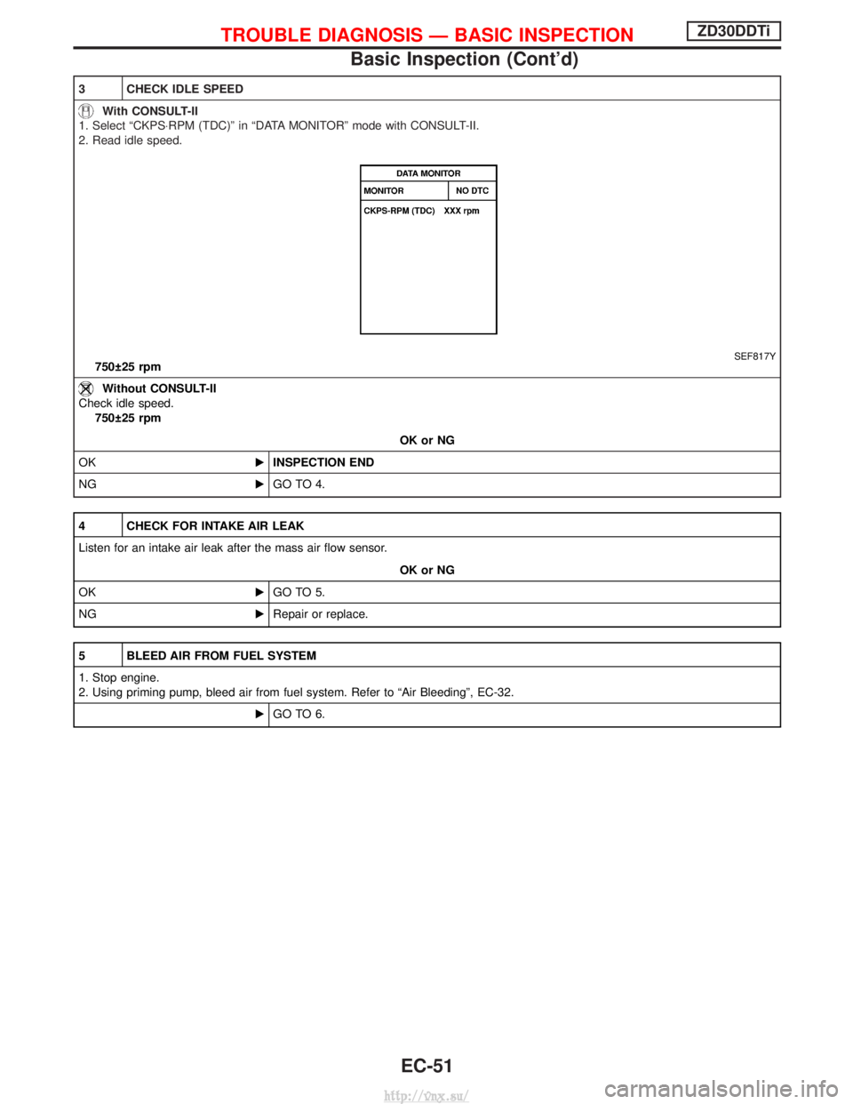
3 CHECK IDLE SPEED
With CONSULT-II
1. Select ªCKPS×RPM (TDC)º in ªDATA MONITORº mode with CONSULT-II.
2. Read idle speed.
SEF817Y750 25 rpm
Without CONSULT-II
Check idle speed. 750 25 rpm
OK or NG
OK EINSPECTION END
NG EGO TO 4.
4 CHECK FOR INTAKE AIR LEAK
Listen for an intake air leak after the mass air flow sensor.
OK or NG
OK EGO TO 5.
NG ERepair or replace.
5 BLEED AIR FROM FUEL SYSTEM
1. Stop engine.
2. Using priming pump, bleed air from fuel system. Refer to ªAir Bleedingº, EC-32.
EGO TO 6.
TROUBLE DIAGNOSIS Ð BASIC INSPECTIONZD30DDTi
Basic Inspection (Cont'd)
EC-51
http://vnx.su/
Page 330 of 1833
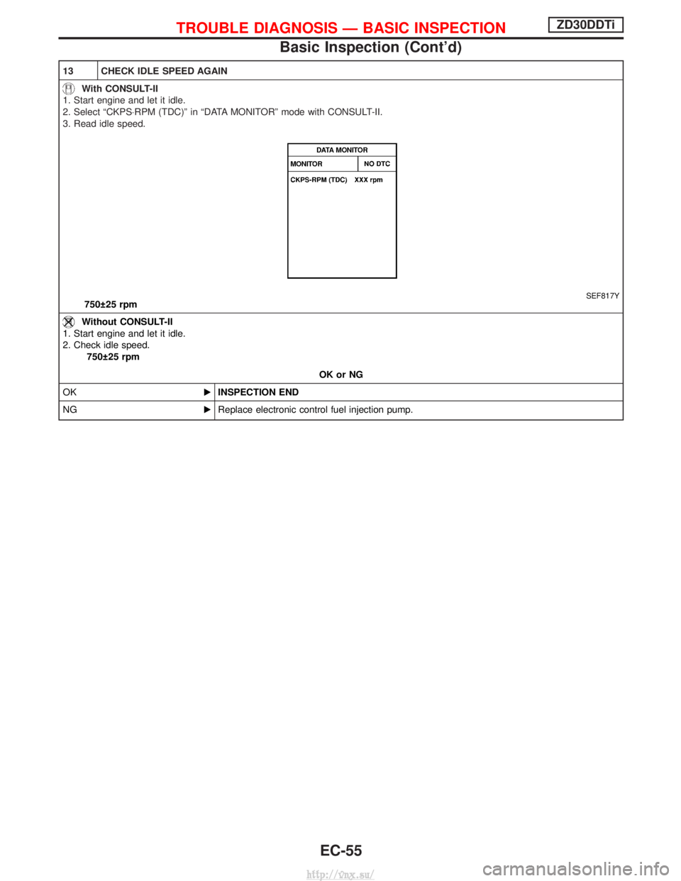
13 CHECK IDLE SPEED AGAIN
With CONSULT-II
1. Start engine and let it idle.
2. Select ªCKPS×RPM (TDC)º in ªDATA MONITORº mode with CONSULT-II.
3. Read idle speed.
SEF817Y750 25 rpm
Without CONSULT-II
1. Start engine and let it idle.
2. Check idle speed. 750 25 rpm
OK or NG
OK EINSPECTION END
NG EReplace electronic control fuel injection pump.
TROUBLE DIAGNOSIS Ð BASIC INSPECTIONZD30DDTi
Basic Inspection (Cont'd)
EC-55
http://vnx.su/
Page 331 of 1833
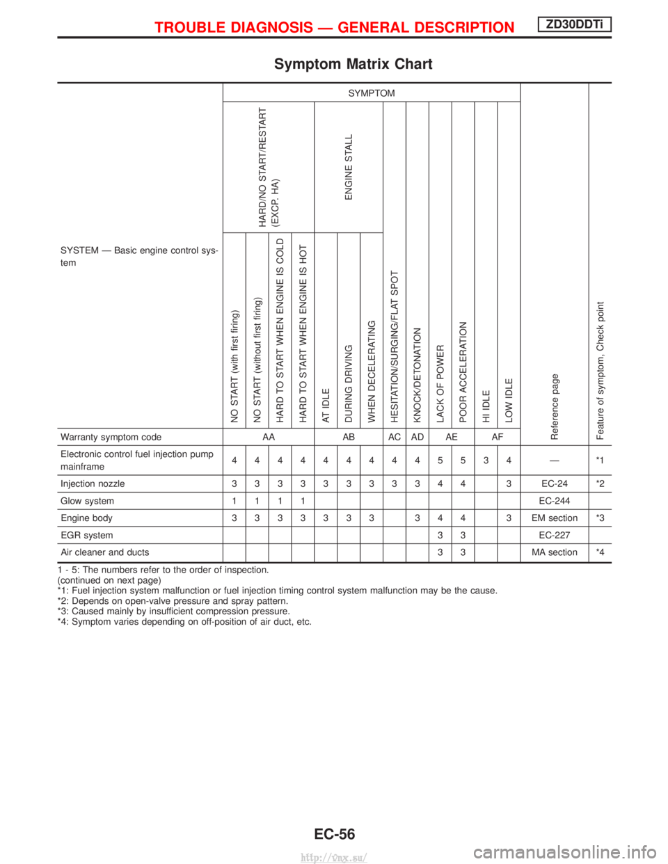
Symptom Matrix Chart
SYSTEM Ð Basic engine control sys-
temSYMPTOM
Reference page
Feature of symptom, Check pointHARD/NO START/RESTART
(EXCP. HA)
ENGINE STALL
HESITATION/SURGING/FLAT SPOT
KNOCK/DETONATION
LACK OF POWER
POOR ACCELERATION
HI IDLE
LOW IDLE NO START (with first firing)
NO START (without first firing)
HARD TO START WHEN ENGINE IS COLD
HARD TO START WHEN ENGINE IS HOT
AT IDLE
DURING DRIVING
WHEN DECELERATINGWarranty symptom code AAAB AC AD AE AF
Electronic control fuel injection pump
mainframe 4444444445534 Ð *1
Injection nozzle 33333333344 3 EC-24 *2
Glow system 1111 EC-244
Engine body 3333333 344 3 EM section *3
EGR system 3 3 EC-227
Air cleaner and ducts 3 3 MA section *4
1 - 5: The numbers refer to the order of inspection.
(continued on next page)
*1: Fuel injection system malfunction or fuel injection timing control system malfunction may be the cause.
*2: Depends on open-valve pressure and spray pattern.
*3: Caused mainly by insufficient compression pressure.
*4: Symptom varies depending on off-position of air duct, etc.
TROUBLE DIAGNOSIS Ð GENERAL DESCRIPTIONZD30DDTi
EC-56
http://vnx.su/
Page 332 of 1833
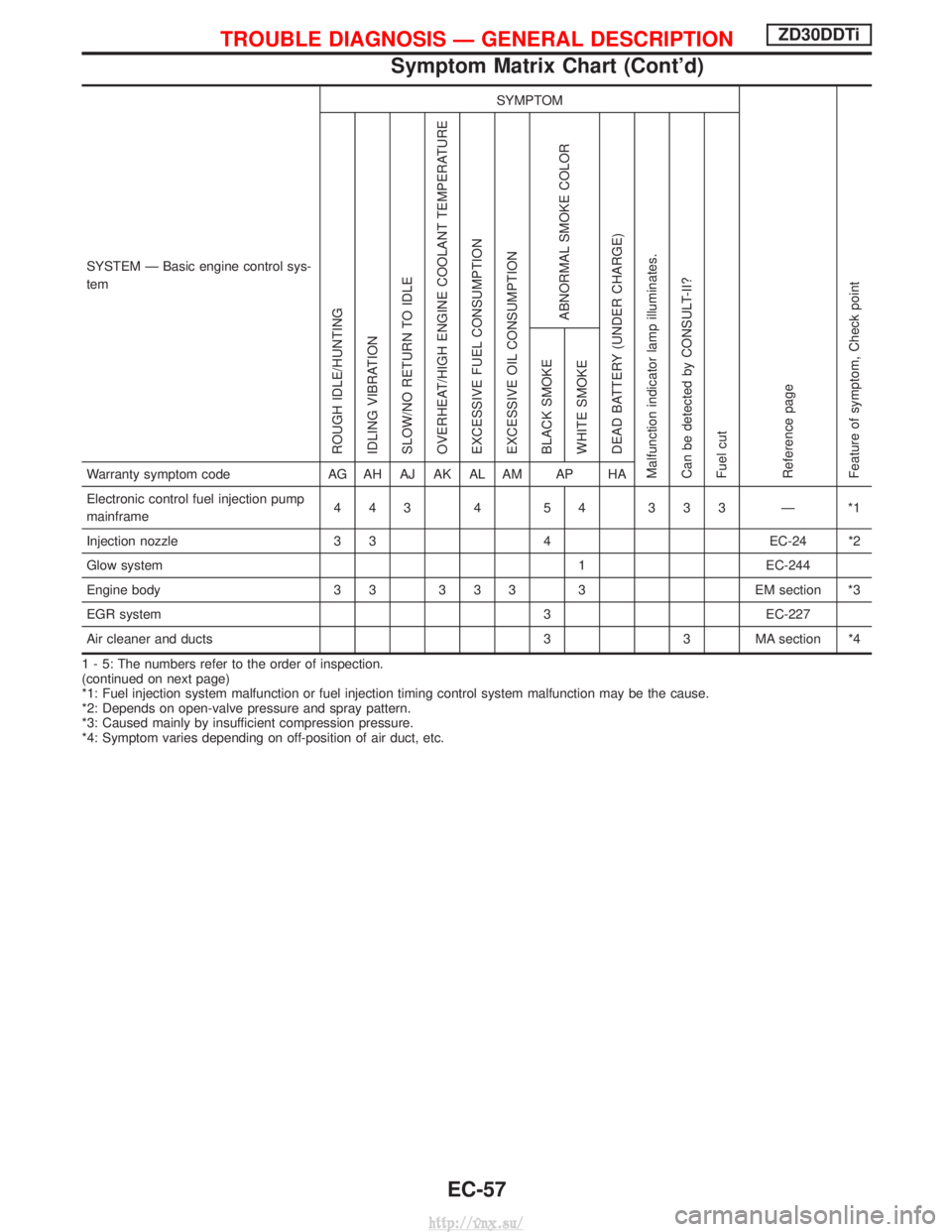
SYSTEM Ð Basic engine control sys-
temSYMPTOM
Reference page
Feature of symptom, Check pointROUGH IDLE/HUNTING
IDLING VIBRATION
SLOW/NO RETURN TO IDLE
OVERHEAT/HIGH ENGINE COOLANT TEMPERATURE
EXCESSIVE FUEL CONSUMPTION
EXCESSIVE OIL CONSUMPTION
ABNORMAL SMOKE COLOR
DEAD BATTERY (UNDER CHARGE)
Malfunction indicator lamp illuminates.
Can be detected by CONSULT-II?
Fuel cut BLACK SMOKE
WHITE SMOKEWarranty symptom code
AG AH AJ AK AL AM AP HA
Electronic control fuel injection pump
mainframe 443 4 54 333 Ð *1
Injection nozzle 3 34 EC-24 *2
Glow system 1 EC-244
Engine body 3 3 3 3 3 3 EM section *3
EGR system 3 EC-227
Air cleaner and ducts 3 3 MA section *4
1 - 5: The numbers refer to the order of inspection.
(continued on next page)
*1: Fuel injection system malfunction or fuel injection timing control system malfunction may be the cause.
*2: Depends on open-valve pressure and spray pattern.
*3: Caused mainly by insufficient compression pressure.
*4: Symptom varies depending on off-position of air duct, etc.
TROUBLE DIAGNOSIS Ð GENERAL DESCRIPTIONZD30DDTi
Symptom Matrix Chart (Cont'd)
EC-57
http://vnx.su/
Page 333 of 1833
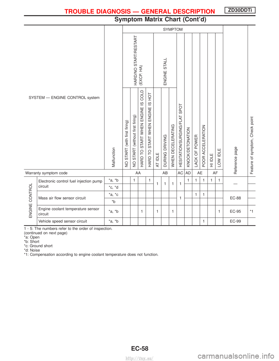
SYSTEM Ð ENGINE CONTROL system
Malfunction
SYMPTOM
Reference page
Feature of symptom, Check pointHARD/NO START/RESTART
(EXCP. HA)
ENGINE STALL
HESITATION/SURGING/FLAT SPOT
KNOCK/DETONATION
LACK OF POWER
POOR ACCELERATION
HI IDLE
LOW IDLE NO START (with first firing)
NO START (without first firing)
HARD TO START WHEN ENGINE IS COLD
HARD TO START WHEN ENGINE IS HOT
AT IDLE
DURING DRIVING
WHEN DECELERATINGWarranty symptom code AAAB AC AD AE AF
ENGINE CONTROL
Electronic control fuel injection pump
circuit *a, *b 1 1
111111111
Ð
*c, *d
Mass air flow sensor circuit *a, *c
111
EC-88
*b
Engine coolant temperature sensor
circuit *a, *b 1 1 1 1 EC-95 *1
Vehicle speed sensor circuit *a, *b 1 EC-99
1 - 5: The numbers refer to the order of inspection.
(continued on next page)
*a: Open
*b: Short
*c: Ground short
*d: Noise
*1: Compensation according to engine coolant temperature does not function.
TROUBLE DIAGNOSIS Ð GENERAL DESCRIPTIONZD30DDTi
Symptom Matrix Chart (Cont'd)
EC-58
http://vnx.su/
Page 334 of 1833
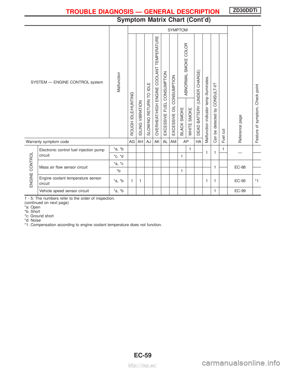
SYSTEM Ð ENGINE CONTROL system
Malfunction
SYMPTOM
Reference page
Feature of symptom, Check pointROUGH IDLE/HUNTING
IDLING VIBRATION
SLOW/NO RETURN TO IDLE
OVERHEAT/HIGH ENGINE COOLANT TEMPERATURE
EXCESSIVE FUEL CONSUMPTION
EXCESSIVE OIL CONSUMPTION
ABNORMAL SMOKE COLOR
DEAD BATTERY (UNDER CHARGE)
Malfunction indicator lamp illuminates.
Can be detected by CONSULT-II?
Fuel cut BLACK SMOKE
WHITE SMOKEWarranty symptom code
AG AH AJ AK AL AM AP HA
ENGINE CONTROL
Electronic control fuel injection pump
circuit*a, *b 1
111
Ð
*c, *d 1
Mass air flow sensor circuit *a, *c
1 EC-88
*b 1
Engine coolant temperature sensor
circuit *a, *b 1 1 1 1 EC-95 *1
Vehicle speed sensor circuit *a, *b 1 EC-99
1 - 5: The numbers refer to the order of inspection.
(continued on next page)
*a: Open
*b: Short
*c: Ground short
*d: Noise
*1: Compensation according to engine coolant temperature does not function.
TROUBLE DIAGNOSIS Ð GENERAL DESCRIPTIONZD30DDTi
Symptom Matrix Chart (Cont'd)
EC-59
http://vnx.su/
Page 341 of 1833
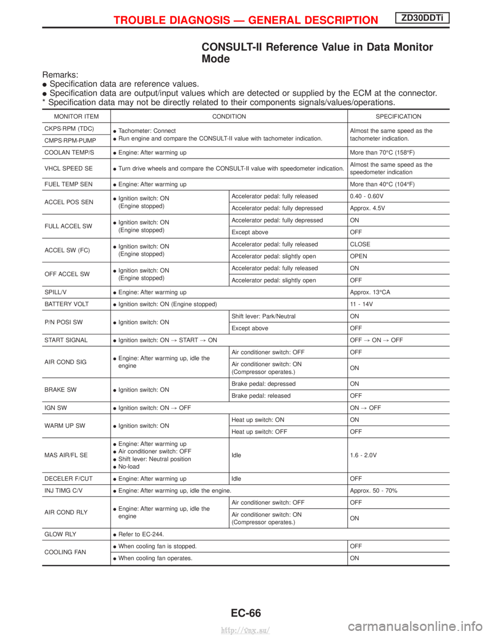
CONSULT-II Reference Value in Data Monitor
Mode
Remarks:
ISpecification data are reference values.
I Specification data are output/input values which are detected or supplied by the ECM at the connector.
* Specification data may not be directly related to their components signals/values/operations.
MONITOR ITEM CONDITION SPECIFICATION
CKPS×RPM (TDC) ITachometer: Connect
I Run engine and compare the CONSULT-II value with tachometer indication. Almost the same speed as the
tachometer indication.
CMPS×RPM-PUMP
COOLAN TEMP/S IEngine: After warming up More than 70ÉC (158ÉF)
VHCL SPEED SE ITurn drive wheels and compare the CONSULT-II value with speedometer indication. Almost the same speed as the
speedometer indication
FUEL TEMP SEN IEngine: After warming up More than 40ÉC (104ÉF)
ACCEL POS SEN I
Ignition switch: ON
(Engine stopped) Accelerator pedal: fully released
0.40 - 0.60V
Accelerator pedal: fully depressed Approx. 4.5V
FULL ACCEL SW I
Ignition switch: ON
(Engine stopped) Accelerator pedal: fully depressed ON
Except above
OFF
ACCEL SW (FC) I
Ignition switch: ON
(Engine stopped) Accelerator pedal: fully released
CLOSE
Accelerator pedal: slightly open OPEN
OFF ACCEL SW I
Ignition switch: ON
(Engine stopped) Accelerator pedal: fully released
ON
Accelerator pedal: slightly open OFF
SPILL/V IEngine: After warming up Approx. 13ÉCA
BATTERY VOLT IIgnition switch: ON (Engine stopped) 11 - 14V
P/N POSI SW IIgnition switch: ON Shift lever: Park/Neutral
ON
Except above OFF
START SIGNAL IIgnition switch: ON ,START ,ON OFF ,ON ,OFF
AIR COND SIG I
Engine: After warming up, idle the
engine Air conditioner switch: OFF OFF
Air conditioner switch: ON
(Compressor operates.)
ON
BRAKE SW IIgnition switch: ON Brake pedal: depressed ON
Brake pedal: released OFF
IGN SW IIgnition switch: ON ,OFF ON ,OFF
WARM UP SW IIgnition switch: ON Heat up switch: ON ON
Heat up switch: OFF OFF
MAS AIR/FL SE I
Engine: After warming up
I Air conditioner switch: OFF
I Shift lever: Neutral position
I No-load Idle 1.6 - 2.0V
DECELER F/CUT IEngine: After warming up Idle OFF
INJ TIMG C/V IEngine: After warming up, idle the engine. Approx. 50 - 70%
AIR COND RLY I
Engine: After warming up, idle the
engine Air conditioner switch: OFF OFF
Air conditioner switch: ON
(Compressor operates.)
ON
GLOW RLY IRefer to EC-244.
COOLING FAN I
When cooling fan is stopped. OFF
I When cooling fan operates. ON
TROUBLE DIAGNOSIS Ð GENERAL DESCRIPTIONZD30DDTi
EC-66
http://vnx.su/