steering wheel NISSAN TERRANO 2004 Service Service Manual
[x] Cancel search | Manufacturer: NISSAN, Model Year: 2004, Model line: TERRANO, Model: NISSAN TERRANO 2004Pages: 1833, PDF Size: 53.42 MB
Page 1334 of 1833
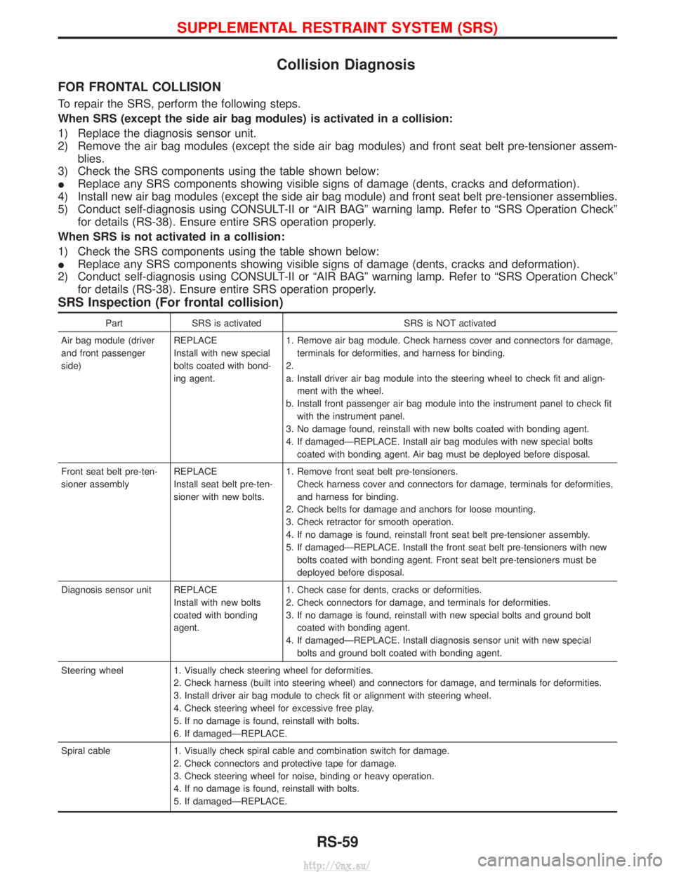
Collision Diagnosis
FOR FRONTAL COLLISION
To repair the SRS, perform the following steps.
When SRS (except the side air bag modules) is activated in a collision:
1) Replace the diagnosis sensor unit.
2) Remove the air bag modules (except the side air bag modules) and front seat belt pre-tensioner assem-blies.
3) Check the SRS components using the table shown below:
I Replace any SRS components showing visible signs of damage (dents, cracks and deformation).
4) Install new air bag modules (except the side air bag module) and front seat belt pre-tensioner assemblies.
5) Conduct self-diagnosis using CONSULT-II or ªAIR BAGº warning lamp. Refer to ªSRS Operation Checkº for details (RS-38). Ensure entire SRS operation properly.
When SRS is not activated in a collision:
1) Check the SRS components using the table shown below:
I Replace any SRS components showing visible signs of damage (dents, cracks and deformation).
2) Conduct self-diagnosis using CONSULT-II or ªAIR BAGº warning lamp. Refer to ªSRS Operation Checkº for details (RS-38). Ensure entire SRS operation properly.
SRS Inspection (For frontal collision)
Part SRS is activated SRS is NOT activated
Air bag module (driver
and front passenger
side) REPLACE
Install with new special
bolts coated with bond-
ing agent.1. Remove air bag module. Check harness cover and connectors for damage,
terminals for deformities, and harness for binding.
2.
a. Install driver air bag module into the steering wheel to check fit and align- ment with the wheel.
b. Install front passenger air bag module into the instrument panel to check fit with the instrument panel.
3. No damage found, reinstall with new bolts coated with bonding agent.
4. If damagedÐREPLACE. Install air bag modules with new special bolts coated with bonding agent. Air bag must be deployed before disposal.
Front seat belt pre-ten-
sioner assembly REPLACE
Install seat belt pre-ten-
sioner with new bolts.1. Remove front seat belt pre-tensioners.
Check harness cover and connectors for damage, terminals for deformities,
and harness for binding.
2. Check belts for damage and anchors for loose mounting.
3. Check retractor for smooth operation.
4. If no damage is found, reinstall front seat belt pre-tensioner assembly.
5. If damagedÐREPLACE. Install the front seat belt pre-tensioners with new bolts coated with bonding agent. Front seat belt pre-tensioners must be
deployed before disposal.
Diagnosis sensor unit REPLACE Install with new bolts
coated with bonding
agent.1. Check case for dents, cracks or deformities.
2. Check connectors for damage, and terminals for deformities.
3. If no damage is found, reinstall with new special bolts and ground bolt
coated with bonding agent.
4. If damagedÐREPLACE. Install diagnosis sensor unit with new special bolts and ground bolt coated with bonding agent.
Steering wheel 1. Visually check steering wheel for deformities. 2. Check harness (built into steering wheel) and connectors for damage, and terminals for deformities.
3. Install driver air bag module to check fit or alignment with steering wheel.
4. Check steering wheel for excessive free play.
5. If no damage is found, reinstall with bolts.
6. If damagedÐREPLACE.
Spiral cable 1. Visually check spiral cable and combination switch for damage. 2. Check connectors and protective tape for damage.
3. Check steering wheel for noise, binding or heavy operation.
4. If no damage is found, reinstall with bolts.
5. If damagedÐREPLACE.
SUPPLEMENTAL RESTRAINT SYSTEM (SRS)
RS-59
http://vnx.su/
Page 1519 of 1833
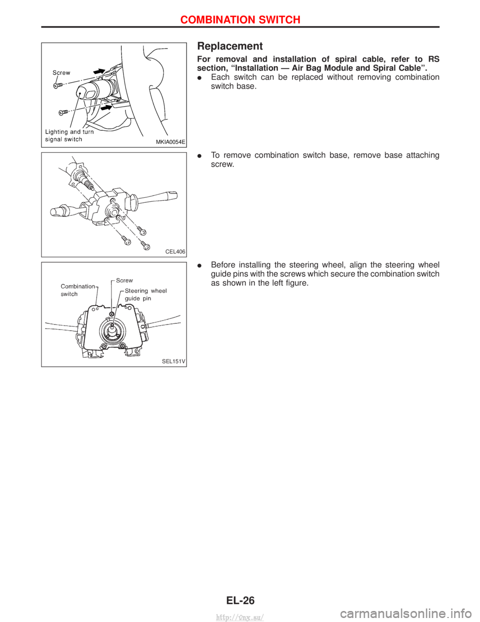
Replacement
For removal and installation of spiral cable, refer to RS
section, ªInstallation Ð Air Bag Module and Spiral Cableº.
IEach switch can be replaced without removing combination
switch base.
I To remove combination switch base, remove base attaching
screw.
I Before installing the steering wheel, align the steering wheel
guide pins with the screws which secure the combination switch
as shown in the left figure.
MKIA0054E
CEL406
SEL151V
COMBINATION SWITCH
EL-26
http://vnx.su/
Page 1831 of 1833
Power steering hydraulic pressure ...................ST-7
Power steering oil pump ...........................ST-16, 22
Power steering system bleeding.......................ST-5
Power supply routing ..................................EL-8, 10
Power window.......................................EL-156, 158
Pre-delivery inspection.....................................MA-3
Priming pump .................................................EC-50
Propeller shaft ............................................PD-5, 57
Propeller shaft greasing...........................MA-36, 38
Propeller shaft inspection ........................MA-36, 38
Propeller shaft on vehicle service ....................PD-6
Pump communication line (ElectronicFuel Injection Pump) ................................EC-180
Pump control module (Electronic Fuel Injection Pump).........................................EC-194
R
Radiator ....................................................LC-14, 32
Rear axle................................................RA-4, 6, 12
Rear bumper .....................................................BT-8
Rear case (Transfer)...................................TF-9, 24
Rear combination lamp removal andinstallation .....................................................BT-8
Rear door ........................................................BT-12
Rear door trim...........................................BT-18, 19
Rear drum brake ............................................BR-32
Rear fog lamp .................................................EL-58
Rear side window .....................................BT-21, 43
Rear suspension ........................................RA-4, 12
Rear window defogger .................EL-125, 132, 133
Refrigerant connection precaution ...................HA-4
Refrigerant general precaution.........................HA-3
Refrigerant lines .............................................HA-17
Refrigeration cycle............................................HA-9
REMOTE - Wiring diagram ...........................EL-145
Removal and installation (A/T)......................AT-121
Removal and installation (Transfer) ..................TF-7
Reverse clutch ..............................................AT-156
Reverse idler shaft (M/T)................................MT-11
Reverse main gear (M/T) ...............................MT-11
Revolution sensor (A/T) ..........................AT-52, 119
R/FOG - Wiring diagram .................................EL-58
Ring gear diff. inspection .........................PD-20, 42
Rocker cover ..................................................EM-20
Roof trim .........................................................BT-20
Rotor disc (front) .............................................FA-18
S
Screw jack .......................................................GI-31
Seal - See Exterior .........................................BT-21
Seat belt inspection .................................MA-36, 45
Seat belt pre-tensioner ...............................RS-2, 11
Seat belt pre-tensioner disposal ....................RS-22
Seat belt, front ..................................................RS-4
Seat, front .......................................................BT-34
Seat, second (2nd) .........................................BT-37 Seat, third (3rd) ...............................................BT-39
Second (2nd) seat ..........................................BT-37
Self-diagnostic results ............................EC-35, 347
Shift control (Transfer) ..............................TF-11, 24
Shift control components
(M/T) ............................MT-13, 14, 15, 21, 23, 31
Shift fork (M/T) ...............................................MT-13
Shift schedule................................................AT-201
Shift solenoid valve A (A/T).............................AT-65
Shift solenoid valve B (A/T) ............................AT-68
Shock absorber (front) ....................................FA-30
Shock absorber (rear) ..............................RA-14, 16
Side air bag ....................................................RS-20
Side air bag (satellite) sensor ........................RS-15
Side bearing preload diff. ...............................PD-24
Side trim....................................................BT-18, 21
Side window - See Rear side window ............BT-21
S/LOCK - Wiring diagram .............................EL-184
SMJ (super multiple junction) .......................Foldout
Speedometer...................................................EL-86
Spill valve .....................................................EC-187
Spiral cable.....................................................RS-16
SROOF - Wiring diagram .............................EL-153
SRS - See Supplemental Restraint System ..........................................................RS-8
SRS - Wiring diagram ....................................RS-34
SRS Trouble diagnoses .................................RS-28
S/SIG - Wiring diagram ................................EC-253
Stabilizer bar (front) ....................................FA-4, 33
Stabilizer bar (rear) ..................................RA-15, 16
Stall test (A/T) .........................................AT-27, 201
Standardized relay ............................................EL-6
START - Wiring diagram ................................SC-14
Start signal ...................................................EC-253
Starter .............................................................SC-17
Starting system...............................................SC-13
Steering gear and linkage inspection ......MA-36, 43
Steering gear oil level ..............................MA-36, 44
Steering gear, linkage and transfer gear inspection ..............................MA-36, 43, 44
Steering linkage ........................................ST-17, 22
Steering switch................................................EL-27
Steering wheel and column ........................ST-8, 22
Steering wheel play ..........................................ST-4
Steering wheel turning force .............................ST-6
Stop lamp ........................................................EL-52
Stop lamp switch ..................................EC-209, 426
STOP/L - Wiring diagram................................EL-52
Striking rod (M/T) ...........................................MT-13
Sub-gear (M/T) ...............................................MT-11
Sunroof............................................................BT-40
Sunroof, electric ............................................EL-153
Super lock ....................EL-171, 179, 180, 182, 192
Supplemental Restraint System .......................RS-8
Swirl control valve control solenoid valve .........................................................EC-271
SWL/V - Wiring diagram ..............................EC-273
Symptom matrix chart ............................EC-56, 363
ALPHABETICAL INDEX
IDX-6
http://vnx.su/