Ignition wiring NISSAN TERRANO 2004 Service Repair Manual
[x] Cancel search | Manufacturer: NISSAN, Model Year: 2004, Model line: TERRANO, Model: NISSAN TERRANO 2004Pages: 1833, PDF Size: 53.42 MB
Page 18 of 1833

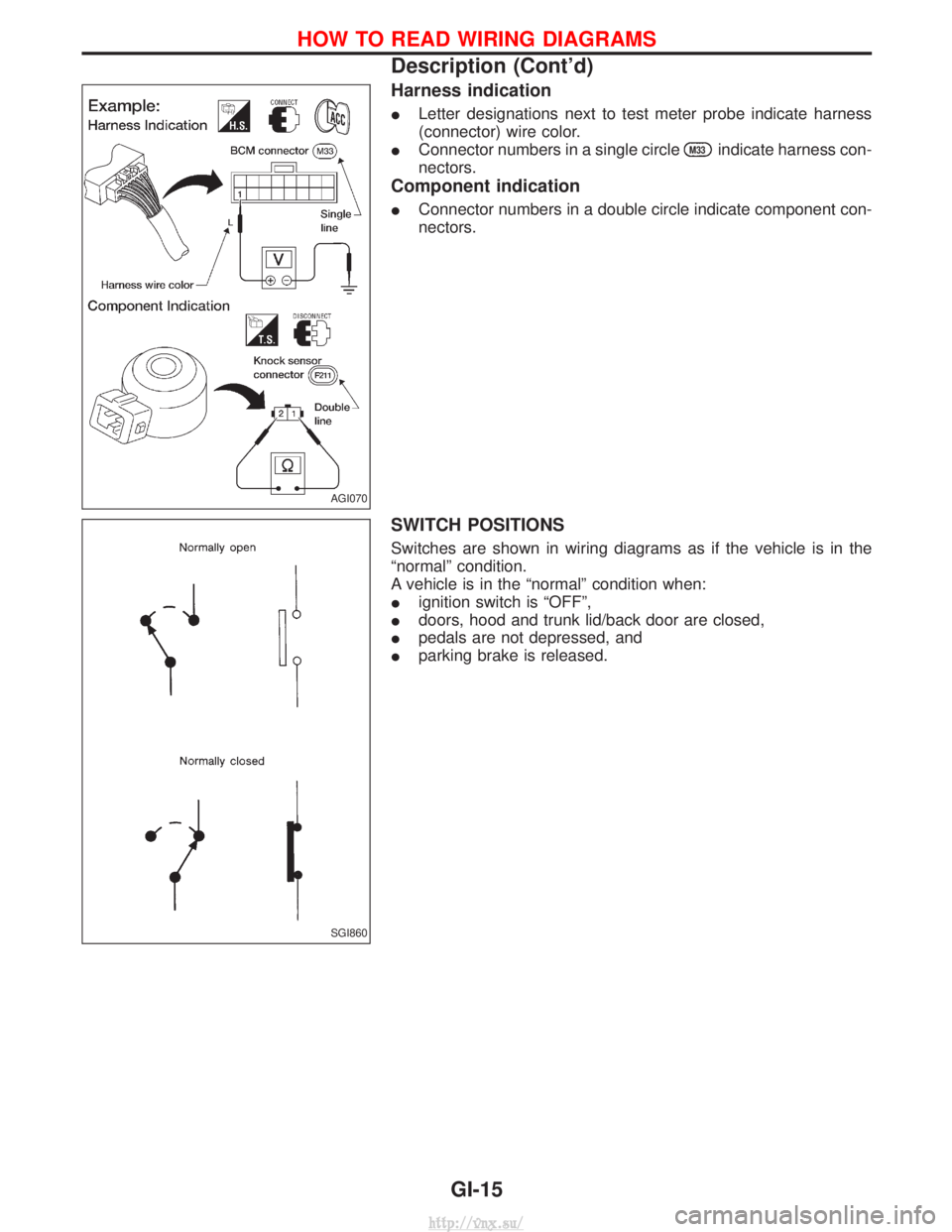
Harness indication
ILetter designations next to test meter probe indicate harness
(connector) wire color.
I Connector numbers in a single circle
M33indicate harness con-
nectors.
Component indication
I Connector numbers in a double circle indicate component con-
nectors.
SWITCH POSITIONS
Switches are shown in wiring diagrams as if the vehicle is in the
ªnormalº condition.
A vehicle is in the ªnormalº condition when:
Iignition switch is ªOFFº,
I doors, hood and trunk lid/back door are closed,
I pedals are not depressed, and
I parking brake is released.
AGI070
SGI860
HOW TO READ WIRING DIAGRAMS
Description (Cont'd)
GI-15
http://vnx.su/
Page 357 of 1833

DIAGNOSTIC PROCEDURE
1 INSPECTION START
Start engine.
Is engine running?YesorNo
Ye s EGO TO 14.
No EGO TO 2.
2 CHECK ECM POWER SUPPLY CIRCUIT-I
1. Turn ignition switch ªONº.
2. Check voltage between ECM terminal 38 and ground with CONSULT-II or tester.
SEF397Y
OK or NG
OK EGO TO 4.
NG EGO TO 3.
3 DETECT MALFUNCTIONING PART
Check the following.
I10A fuse
I Harness for open or short between ECM and fuse
ERepair open circuit or short to ground or short to power in harness or connectors.
4 CHECK ECM GROUND CIRCUIT FOR OPEN AND SHORT
1. Turn ignition switch ªOFFº.
2. Disconnect ECM harness connector.
3. Check harness continuity between ECM terminals 39, 43, 106, 112, 118 and engine ground. Refer to Wiring Diagram.
Continuity should exist.
4. Also check harness for short to ground and short to power.
OK or NG
OK EGO TO 6.
NG EGO TO 5.
TROUBLE DIAGNOSIS FOR POWER SUPPLYZD30DDTi
Main Power Supply and Ground Circuit
(Cont'd)
EC-82
http://vnx.su/
Page 361 of 1833

14 CHECK ECM POWER SUPPLY CIRCUIT-V
1. Reconnect all harness connectors disconnected.
2. Turn ignition switch ªONº.
3. Check voltage between ECM terminal 102 and ground with CONSULT-II or tester.
SEF290Z
OK or NG
OK EGO TO 16.
NG EGO TO 15.
15 DETECT MALFUNCTIONING PART
Check the following.
I10A fuse
I Harness for open or short between ECM and fuse
ERepair open circuit or short to ground or short to power in harness or connectors.
16 CHECK ECM POWER SUPPLY CIRCUIT-VI
1. Turn ignition switch ªOFFº.
2. Disconnect ECM relay.
MEC021E
3. Disconnect ECM harness connector.
4. Check harness continuity between ECM terminals 56, 61, 116 and ECM relay terminal 5. Refer to Wiring Diagram.
Continuity should exist.
5. Also check harness for short to ground and short to power.
OK or NG
OK EGO TO 18.
NG EGO TO 17.
TROUBLE DIAGNOSIS FOR POWER SUPPLYZD30DDTi
Main Power Supply and Ground Circuit
(Cont'd)
EC-86
http://vnx.su/
Page 368 of 1833

3 CHECK MAFS GROUND CIRCUIT FOR OPEN AND SHORT
1. Turn ignition switch ªOFFº.
2. Loosen and retighten engine ground screws.
MEC994D
3. Check harness continuity between mass air flow sensor terminal 3 and engine ground. Refer to Wiring Diagram.Continuity should exist.
4. Also check harness for short to ground and short to power.
OK or NG
OK EGO TO 5.
NG EGO TO 4.
4 DETECT MALFUNCTIONING PART
Check the following.
IHarness connectors F135, M842 (RHD models)
I Harness for open or short between mass air flow sensor and ECM
ERepair open circuit or short to ground or short to power in harness or connectors.
5 CHECK MAFS INPUT SIGNAL CIRCUIT FOR OPEN AND SHORT
1. Disconnect ECM harness connector.
2. Check harness continuity between mass air flow sensor terminal 5 and ECM terminal 35. Refer to Wiring Diagram.
Continuity should exist.
3. Also check harness for short to ground and short to power.
OK or NG
OK EGO TO 7.
NG EGO TO 6.
6 DETECT MALFUNCTIONING PART
Check the following.
IHarness connectors F135, M842 (RHD models)
I Harness for open or short between mass air flow sensor and ECM
ERepair open circuit or short to ground or short to power in harness or connectors.
DTC 0102 MASS AIR FLOW SENZD30DDTi
Diagnostic Procedure (Cont'd)
EC-93
http://vnx.su/
Page 372 of 1833

Diagnostic Procedure
1 CHECK ECTS POWER SUPPLY CIRCUIT
1. Turn ignition switch ªOFFº.
2. Disconnect engine coolant temperature sensor harness connector.
MEC022E
3. Turn ignition switch ªONº.
4. Check voltage between ECTS terminal 2 and ground with CONSULT-II or tester.
SEF401Y
OK or NG
OK EGO TO 3.
NG EGO TO 2.
2 DETECT MALFUNCTIONING PART
Check the following.
IHarness connectors E225, F108
I Harness connectors F135, M842 (RHD models)
I Harness for open or short between engine control temperature sensor and ECM
ERepair open circuit or short to ground or short to power in harness or connectors.
3 CHECK ECTS GROUND CIRCUIT FOR OPEN AND SHORT
1. Turn ignition switch ªOFFº.
2. Check harness continuity between ECTS terminal 1 and engine ground. Refer to Wiring Diagram.
Continuity should exist.
3. Also check harness for short to ground and short to power.
OK or NG
OK EGO TO 5.
NG EGO TO 4.
DTC 0103 COOLANT TEMP SENZD30DDTi
EC-97
http://vnx.su/
Page 378 of 1833

Diagnostic Procedure
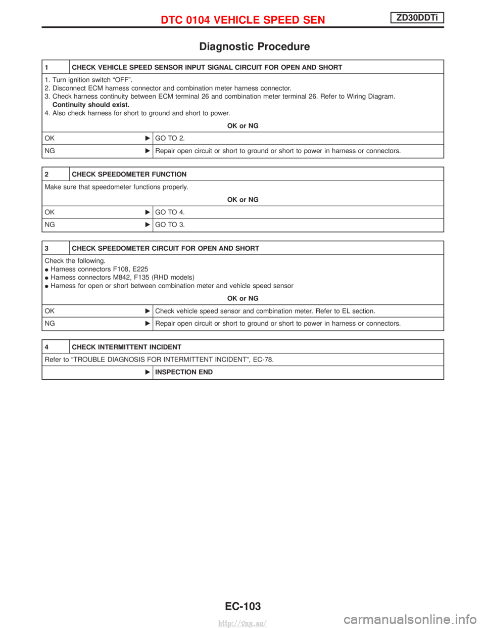
1 CHECK VEHICLE SPEED SENSOR INPUT SIGNAL CIRCUIT FOR OPEN AND SHORT
1. Turn ignition switch ªOFFº.
2. Disconnect ECM harness connector and combination meter harness connector.
3. Check harness continuity between ECM terminal 26 and combination meter terminal 26. Refer to Wiring Diagram.Continuity should exist.
4. Also check harness for short to ground and short to power.
OK or NG
OK EGO TO 2.
NG ERepair open circuit or short to ground or short to power in harness or connectors.
2 CHECK SPEEDOMETER FUNCTION
Make sure that speedometer functions properly.
OK or NG
OK EGO TO 4.
NG EGO TO 3.
3 CHECK SPEEDOMETER CIRCUIT FOR OPEN AND SHORT
Check the following.
IHarness connectors F108, E225
I Harness connectors M842, F135 (RHD models)
I Harness for open or short between combination meter and vehicle speed sensor
OK or NG
OK ECheck vehicle speed sensor and combination meter. Refer to EL section.
NG ERepair open circuit or short to ground or short to power in harness or connectors.
4 CHECK INTERMITTENT INCIDENT
Refer to ªTROUBLE DIAGNOSIS FOR INTERMITTENT INCIDENTº, EC-78.
EINSPECTION END
DTC 0104 VEHICLE SPEED SENZD30DDTi
EC-103
http://vnx.su/
Page 382 of 1833

Diagnostic Procedure
1 CHECK ACCELERATOR SWITCH (F/C) GROUND CIRCUIT FOR OPEN AND SHORT
1. Turn ignition switch ªOFFº.
2. Loosen and retighten engine ground screws.
3. Disconnect accelerator switch (F/C) harness connector.
MEC995D
4. Check harness continuity between accelerator switch (F/C) terminal 3 and engine ground. Refer to Wiring Diagram.Continuity should exist.
5. Also check harness for short to ground and short to power.
OK or NG
OK EGO TO 3.
NG EGO TO 2.
2 DETECT MALFUNCTIONING PART
Check the following.
IHarness connectors F108, E225
I Harness connectors M842, F135 (RHD models)
I Harness for open or short between accelerator switch (F/C) and engine ground
ERepair open circuit or short to ground or short to power in harness or connectors.
3 CHECK ACCELERATOR SWITCH (F/C) INPUT SIGNAL CIRCUIT FOR OPEN AND SHORT
1. Disconnect ECM harness connector.
2. Check harness continuity between ECM terminal 29 and accelerator switch (F/C) terminal 1. Refer to Wiring Diagram.
Continuity should exist.
3. Also check harness for short to ground and short to power.
OK or NG
OK EGO TO 4.
NG ERepair open circuit or short to ground or short to power in harness or connectors.
DTC 0203 ACCEL POS SW (F/C)ZD30DDTi
EC-107
http://vnx.su/
Page 391 of 1833

6 CHECK COOLING FAN GROUND CIRCUIT FOR OPEN AND SHORT
1. Turn ignition switch ªOFFº.
2. Disconnect cooling fan motor harness connector.
MEC024E
3. Check harness continuity as follows. Refer to Wiring Diagram.
MTBL13224. Also check harness for short to ground and short to power.OK or NG
OK EGO TO 8.
NG EGO TO 7.
7 DETECT MALFUNCTIONING PART
Check the following.
IHarness connectors M785, F67 (M/T models)
I Harness for open or short between cooling fan relay and cooling fan motor
I Harness for open or short between cooling fan relay and condenser
I Harness for open or short between cooling fan motor and ground
I Harness for open or short between condenser and ground
ERepair open circuit or short to ground or short to power in harness or connectors.
8 CHECK COOLING FAN OUTPUT SIGNAL CIRCUIT FOR OPEN AND SHORT
1. Disconnect ECM harness connector.
2. Check harness continuity between ECM terminal 14 and cooling fan relay terminal 1. Refer to Wiring Diagram.
Continuity should exist.
3. Also check harness for short to ground and short to power.
OK or NG
OK EGO TO 10.
NG EGO TO 9.
9 DETECT MALFUNCTIONING PART
Check the following.
IHarness connectors M787, F66
I Harness for open or short between cooling fan relay and ECM
ERepair open circuit or short to ground or short to power in harness or connectors.
DTC 0208 OVER HEATZD30DDTi
Diagnostic Procedure (Cont'd)
EC-116
http://vnx.su/
Page 403 of 1833

Diagnostic Procedure
1 CHECK ELECTRONIC CONTROL FUEL INJECTION PUMP POWER SUPPLY CIRCUIT
1. Turn ignition switch ªOFFº.
2. Disconnect electronic control fuel injection pump harness connector.
MEC025E
3. Turn ignition switch ªONº.
4. Check voltage between electronic control fuel injection pump terminal 7 and ground.
MEC977DVoltage: Battery voltageOK or NG
OK EGO TO 3.
NG EGO TO 2.
2 DETECT MALFUNCTIONING PART
Check the following.
IHarness connectors M787, F66 (LHD models)
I Harness connectors F108, E225
I Harness connectors E220, E231
I Harness connectors M842, F135 (RHD models)
I Harness for open or short between electronic control fuel injection pump and ECM
I Harness for open or short between electronic control fuel injection pump and ECM relay
ERepair open circuit or short to ground or short to power in harness or connectors.
3 CHECK ELECTRONIC CONTROL FUEL INJECTION PUMP GROUND CIRCUIT FOR OPEN AND SHORT
1. Turn ignition switch ªOFFº.
2. Check harness continuity between electronic control fuel injection pump terminal 6 and ground. Refer to Wiring Diagram.
Continuity should exist.
3. Also check harness for short to ground and short to power.
OK or NG
OK EGO TO 5.
NG EGO TO 4.
DTC 0402 P9×FUEL TEMP SENZD30DDTi
EC-128
http://vnx.su/
Page 415 of 1833

4 CHECK ACCELERATOR POSITION SENSOR GROUND CIRCUIT FOR OPEN AND SHORT
1. Turn ignition switch ªOFFº.
2. Loosen and retighten engine ground screw.
MEC994D
3. Check harness continuity between accelerator position sensor terminal 3 and engine ground. Refer to Wiring Diagram.Continuity should exist.
4. Also check harness for short to ground and short to power.
OK or NG
OK EGO TO 5.
NG ERepair open circuit or short to ground or short to power in harness or connectors.
5 CHECK ACCELERATOR POSITION SENSOR INPUT SIGNAL CIRCUIT FOR OPEN AND SHORT
1. Disconnect ECM harness connector.
2. Check harness continuity between ECM terminal 23 and accelerator position sensor terminal 2. Refer to Wiring Diagram.
Continuity should exist.
3. Also check harness for short to ground and short to power.
OK or NG
OK (with CONSULT-II) EGO TO 6.
OK (without CONSULT-II) EGO TO 7.
NG ERepair open circuit or short to ground or short to power in harness or connectors.
DTC 0403 ACCEL POS SENSORZD30DDTi
Diagnostic Procedure (Cont'd)
EC-140
http://vnx.su/