brake sensor NISSAN TERRANO 2004 Service Repair Manual
[x] Cancel search | Manufacturer: NISSAN, Model Year: 2004, Model line: TERRANO, Model: NISSAN TERRANO 2004Pages: 1833, PDF Size: 53.42 MB
Page 316 of 1833
![NISSAN TERRANO 2004 Service Repair Manual Monitored item
[Unit]ECM
input
signals Main
signals Description Remarks
FUEL TEMP SEN
[ÉC] or [ÉF] qqI
The fuel temperature (sent from elec-
tronic control fuel injection pump) is dis-
played.
ACCEL NISSAN TERRANO 2004 Service Repair Manual Monitored item
[Unit]ECM
input
signals Main
signals Description Remarks
FUEL TEMP SEN
[ÉC] or [ÉF] qqI
The fuel temperature (sent from elec-
tronic control fuel injection pump) is dis-
played.
ACCEL](/img/5/57394/w960_57394-315.png)
Monitored item
[Unit]ECM
input
signals Main
signals Description Remarks
FUEL TEMP SEN
[ÉC] or [ÉF] qqI
The fuel temperature (sent from elec-
tronic control fuel injection pump) is dis-
played.
ACCEL POS SEN [V] qqI
The accelerator position sensor signal
voltage is displayed.
FULL ACCEL SW
[ON/OFF] qqI
Indicates [ON/OFF] condition from the
accelerator position switch signal.
ACCEL SW (FC)
[OPEN/CLOSE] qqI
Indicates [OPEN/CLOSE] condition from
the accelerator switch (FC) signal.
OFF ACCEL SW
[ON/OFF] qqI
Indicates [ON/OFF] condition from the
accelerator position switch signal.
SPILL/V [ÉCA] qI
The control position of spill valve (sent
from electronic control fuel injection
pump) is displayed.
BATTERY VOLT [V] qqI
The power supply voltage of ECM is dis-
played.
P/N POSI SW
[ON/OFF] qqI
Indicates [ON/OFF] condition from the
park/neutral position switch signal.
START SIGNAL
[ON/OFF] qqI
Indicates [ON/OFF] condition from the
starter signal. I
After starting the engine, [OFF] is dis-
played regardless of the starter signal.
AIR COND SIG
[ON/OFF] qqI
Indicates [ON/OFF] condition of the air
conditioner switch as determined by the
air conditioner signal.
BRAKE SW [ON/OFF] qqI
Indicates [ON/OFF] condition from the
stop lamp switch signal.
IGN SW
[ON/OFF] qqI
Indicates [ON/OFF] condition from igni-
tion switch signal.
WARM UP SW
[ON/OFF] qI
Indicates [ON/OFF] condition from the
heat up switch signal.
MAS AIR/FL SE [V] qqI
The signal voltage of the mass air flow
sensor is displayed. I
When the engine is stopped, a certain
value is indicated.
DECELER F/CUT
[ON/OFF] qI
The [ON/OFF] condition from decelera-
tion fuel cut signal (sent from electronic
control fuel injection pump) is displayed.
INJ TIMG C/V [%] qI
The duty ratio of fuel injection timing
control valve (sent from electronic control
fuel injection pump) is displayed.
AIR COND RLY
[ON/OFF] qI
Indicates the control condition of the air
conditioner relay (determined by ECM
according to the input signals).
GLOW RLY [ON/OFF] qI
The glow relay control condition (deter-
mined by ECM according to the input
signal) is displayed.
COOLING FAN
[ON/OFF] qI
Indicates the control condition of the
cooling fans (determined by ECM
according to the input signal).
I ON ... Operates.
OFF ... Stopped.
ON BOARD DIAGNOSTIC SYSTEM DESCRIPTIONZD30DDTi
CONSULT-II (Cont'd)
EC-41
http://vnx.su/
Page 347 of 1833
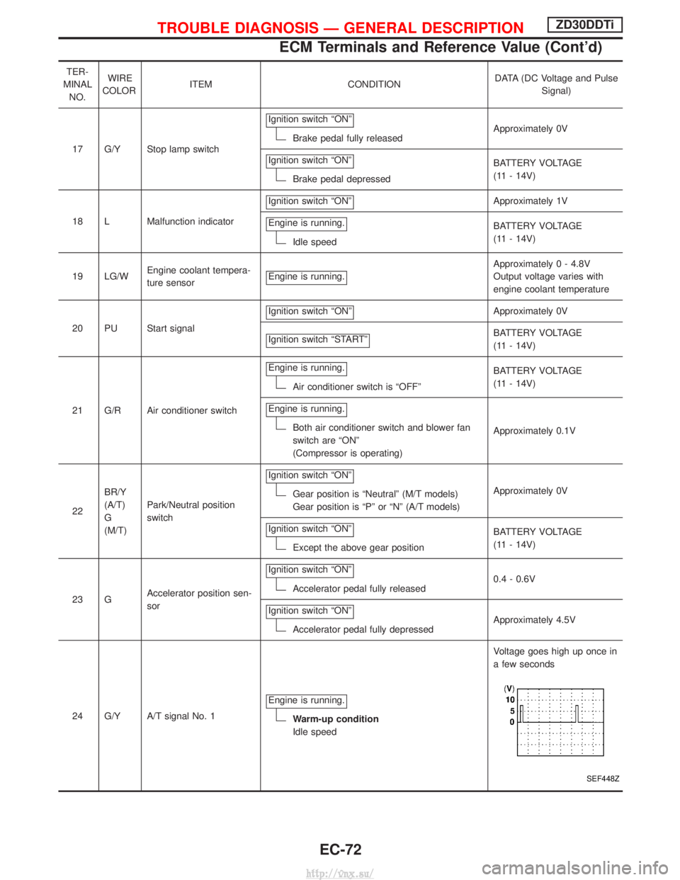
TER-
MINAL NO. WIRE
COLOR ITEM CONDITION DATA (DC Voltage and Pulse
Signal)
17 G/Y Stop lamp switch Ignition switch ªONº
Brake pedal fully released
Approximately 0V
Ignition switch ªONº
Brake pedal depressed BATTERY VOLTAGE
(11 - 14V)
18 L Malfunction indicator Ignition switch ªONº
Approximately 1V
Engine is running.
Idle speed BATTERY VOLTAGE
(11 - 14V)
19 LG/W Engine coolant tempera-
ture sensor Engine is running.
Approximately 0 - 4.8V
Output voltage varies with
engine coolant temperature
20 PU Start signal Ignition switch ªONº
Approximately 0V
Ignition switch ªSTARTº
BATTERY VOLTAGE
(11 - 14V)
21 G/R Air conditioner switch Engine is running.
Air conditioner switch is ªOFFº
BATTERY VOLTAGE
(11 - 14V)
Engine is running.
Both air conditioner switch and blower fan
switch are ªONº
(Compressor is operating) Approximately 0.1V
22 BR/Y
(A/T)
G
(M/T) Park/Neutral position
switch Ignition switch ªONº
Gear position is ªNeutralº (M/T models)
Gear position is ªPº or ªNº (A/T models)
Approximately 0V
Ignition switch ªONº
Except the above gear position BATTERY VOLTAGE
(11 - 14V)
23 G Accelerator position sen-
sor Ignition switch ªONº
Accelerator pedal fully released
0.4 - 0.6V
Ignition switch ªONº
Accelerator pedal fully depressed Approximately 4.5V
24 G/Y A/T signal No. 1 Engine is running.
Warm-up condition
Idle speed Voltage goes high up once in
a few seconds
SEF448Z
TROUBLE DIAGNOSIS Ð GENERAL DESCRIPTIONZD30DDTi
ECM Terminals and Reference Value (Cont'd)
EC-72
http://vnx.su/
Page 588 of 1833
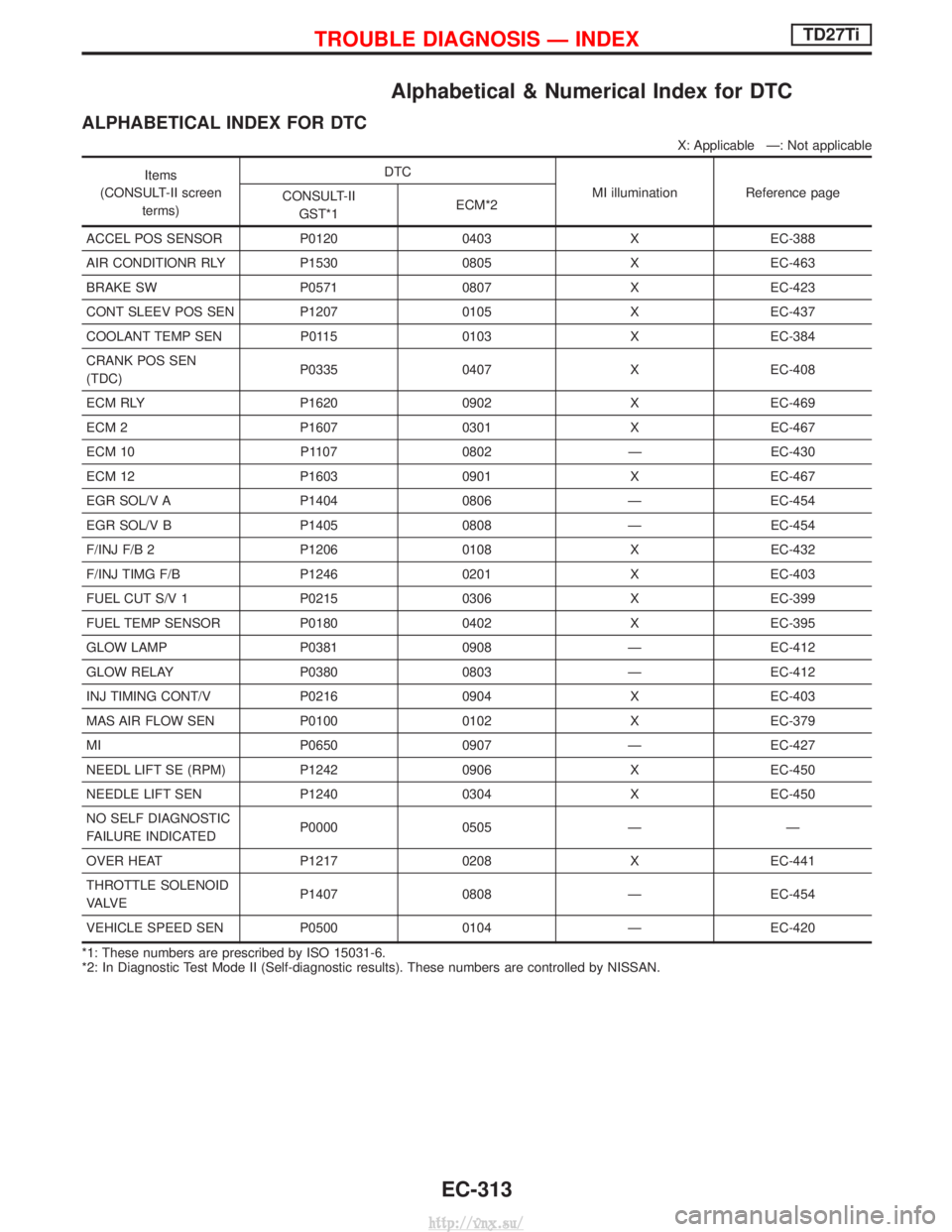
Alphabetical & Numerical Index for DTC
ALPHABETICAL INDEX FOR DTC
X: Applicable Ð: Not applicable
Items
(CONSULT-II screen terms) DTC
MI illuminationReference page
CONSULT-II
GST*1 ECM*2
ACCEL POS SENSOR P0120 0403 X EC-388
AIR CONDITIONR RLY P1530 0805 X EC-463
BRAKE SW P0571 0807 X EC-423
CONT SLEEV POS SEN P1207 0105 X EC-437
COOLANT TEMP SEN P0115 0103 X EC-384
CRANK POS SEN
(TDC) P0335 0407 X EC-408
ECM RLY P1620 0902 X EC-469
ECM 2 P1607 0301 X EC-467
ECM 10 P1107 0802 Ð EC-430
ECM 12 P1603 0901 X EC-467
EGR SOL/V A P1404 0806 Ð EC-454
EGR SOL/V B P1405 0808 Ð EC-454
F/INJ F/B 2 P1206 0108 X EC-432
F/INJ TIMG F/B P1246 0201 X EC-403
FUEL CUT S/V 1 P0215 0306 X EC-399
FUEL TEMP SENSOR P0180 0402 X EC-395
GLOW LAMP P0381 0908 Ð EC-412
GLOW RELAY P0380 0803 Ð EC-412
INJ TIMING CONT/V P0216 0904 X EC-403
MAS AIR FLOW SEN P0100 0102 X EC-379
MI P0650 0907 Ð EC-427
NEEDL LIFT SE (RPM) P1242 0906 X EC-450
NEEDLE LIFT SEN P1240 0304 X EC-450
NO SELF DIAGNOSTIC
FAILURE INDICATED P0000 0505 Ð Ð
OVER HEAT P1217 0208 X EC-441
THROTTLE SOLENOID
VA LV E P1407 0808 Ð EC-454
VEHICLE SPEED SEN P0500 0104 Ð EC-420
*1: These numbers are prescribed by ISO 15031-6.
*2: In Diagnostic Test Mode II (Self-diagnostic results). These numbers are controlled by NISSAN.
TROUBLE DIAGNOSIS Ð INDEXTD27Ti
EC-313
http://vnx.su/
Page 589 of 1833
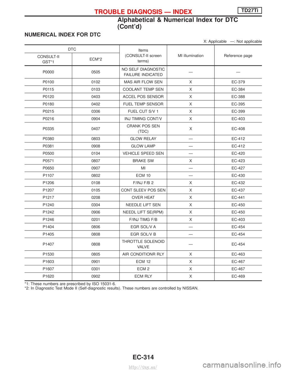
NUMERICAL INDEX FOR DTC
X: Applicable Ð: Not applicable
DTCItems
(CONSULT-II screen terms) MI illumination Reference page
CONSULT-II
GST*1 ECM*2
P0000 0505 NO SELF DIAGNOSTIC
FAILURE INDICATED ÐÐ
P0100 0102 MAS AIR FLOW SEN X EC-379 P0115 0103 COOLANT TEMP SEN X EC-384
P0120 0403 ACCEL POS SENSOR X EC-388
P0180 0402 FUEL TEMP SENSOR X EC-395
P0215 0306 FUEL CUT S/V 1 X EC-399
P0216 0904 INJ TIMING CONT/V X EC-403
P0335 0407 CRANK POS SEN
(TDC) X EC-408
P0380 0803 GLOW RELAY Ð EC-412
P0381 0908 GLOW LAMP Ð EC-412
P0500 0104 VEHICLE SPEED SEN Ð EC-420
P0571 0807 BRAKE SW X EC-423
P0650 0907 MI Ð EC-427 P1107 0802 ECM 10 Ð EC-430
P1206 0108 F/INJ F/B 2 X EC-432
P1207 0105 CONT SLEEV POS SEN X EC-437
P1217 0208 OVER HEAT X EC-441
P1240 0304 NEEDLE LIFT SEN X EC-450
P1242 0906 NEEDL LIFT SE(RPM) X EC-450
P1246 0201 F/INJ TIMG F/B X EC-403
P1404 0806 EGR SOL/V A Ð EC-454
P1405 0808 EGR SOL/V B Ð EC-454
P1407 0808 THROTTLE SOLENOID
VA LV E Ð EC-454
P1530 0805 AIR CONDITIONR RLY X EC-463
P1603 0901 ECM 12 X EC-467
P1607 0301 ECM 2 X EC-467
P1620 0902 ECM RLY X EC-469
*1: These numbers are prescribed by ISO 15031-6.
*2: In Diagnostic Test Mode II (Self-diagnostic results). These numbers are controlled by NISSAN.
TROUBLE DIAGNOSIS Ð INDEXTD27Ti
Alphabetical & Numerical Index for DTC
(Cont'd)
EC-314
http://vnx.su/
Page 603 of 1833
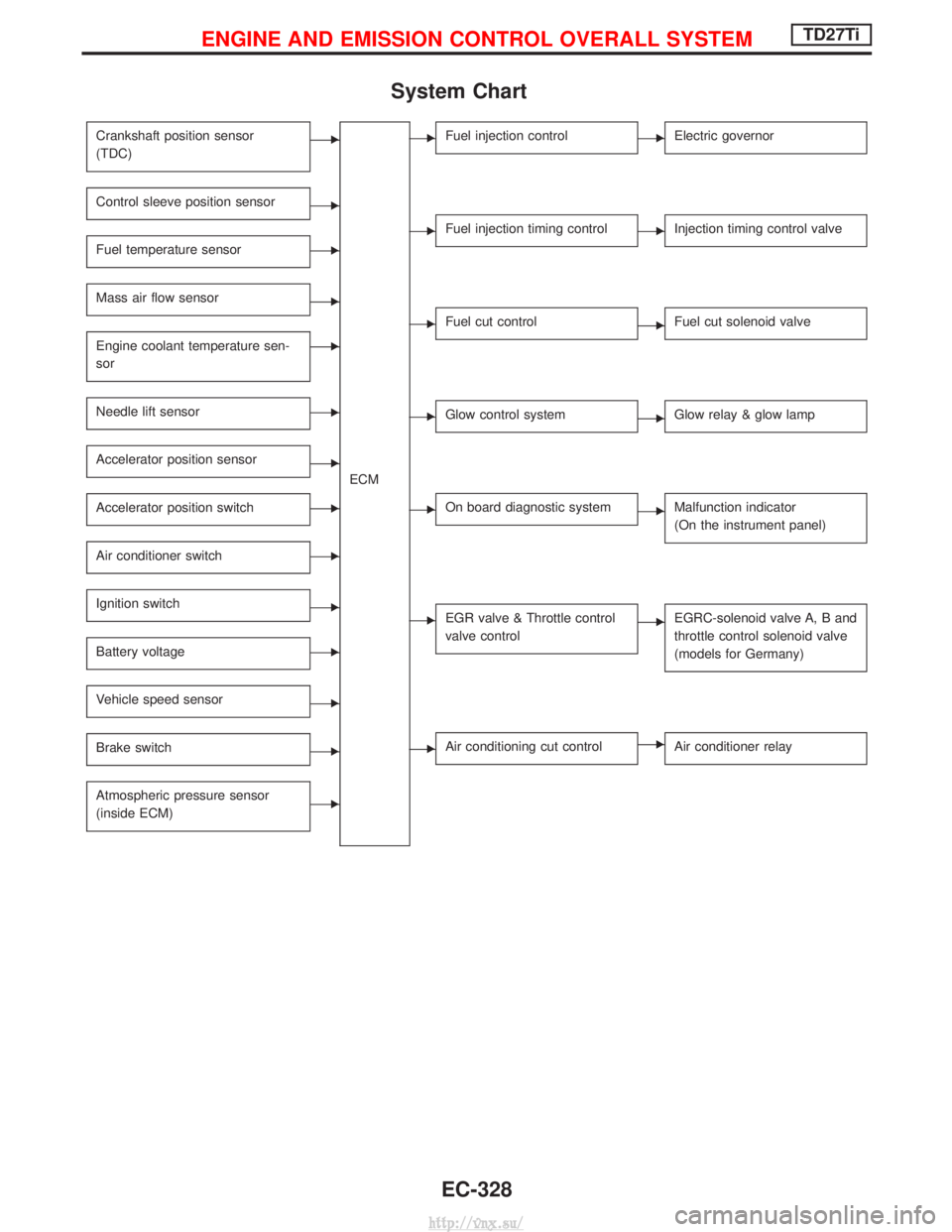
System Chart
Crankshaft position sensor
(TDC)E
ECM
Control sleeve position sensorE
Fuel temperature sensorE
Mass air flow sensorE
Engine coolant temperature sen-
sorE
Needle lift sensorE
Accelerator position sensorE
Accelerator position switchE
Air conditioner switchE
Ignition switchE
Battery voltageE
Vehicle speed sensorE
Brake switchE
Atmospheric pressure sensor
(inside ECM)E
EFuel injection controlEElectric governor
EFuel injection timing controlEInjection timing control valve
EFuel cut controlEFuel cut solenoid valve
EGlow control systemEGlow relay & glow lamp
EOn board diagnostic systemEMalfunction indicator
(On the instrument panel)
EEGR valve & Throttle control
valve controlEEGRC-solenoid valve A, B and
throttle control solenoid valve
(models for Germany)
EAir conditioning cut controlEAir conditioner relay
ENGINE AND EMISSION CONTROL OVERALL SYSTEMTD27Ti
EC-328
http://vnx.su/
Page 626 of 1833
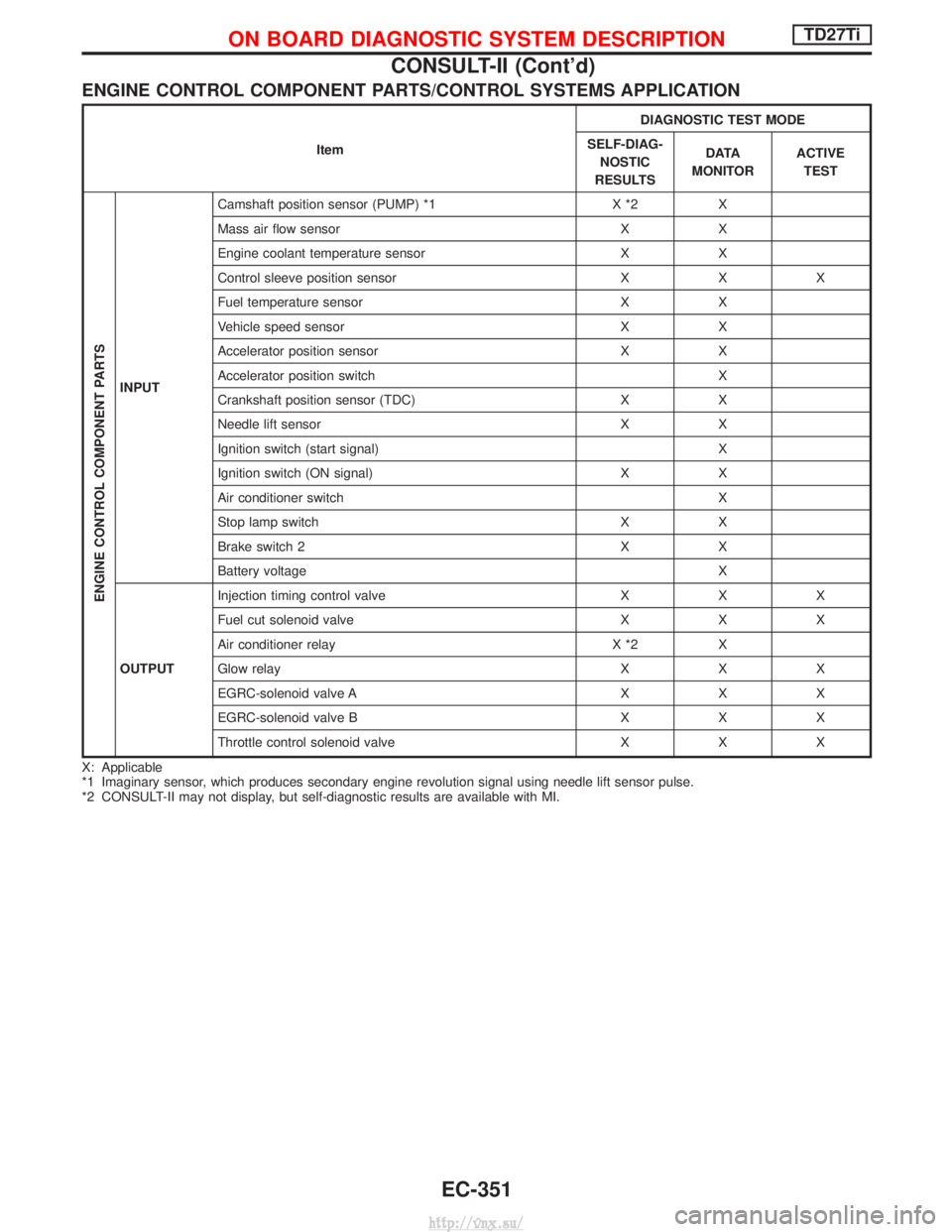
ENGINE CONTROL COMPONENT PARTS/CONTROL SYSTEMS APPLICATION
ItemDIAGNOSTIC TEST MODE
SELF-DIAG- NOSTIC
RESULTS D ATA
MONITOR ACTIVE
TEST
ENGINE CONTROL COMPONENT PARTS
INPUT Camshaft position sensor (PUMP) *1 X *2 X
Mass air flow sensor X X
Engine coolant temperature sensor X X
Control sleeve position sensor X X X
Fuel temperature sensor X X
Vehicle speed sensor X X
Accelerator position sensor X X
Accelerator position switch X
Crankshaft position sensor (TDC) X X
Needle lift sensor X X
Ignition switch (start signal) X
Ignition switch (ON signal) X X
Air conditioner switch X
Stop lamp switch X X
Brake switch 2 X X
Battery voltage X
OUTPUT Injection timing control valve X X X
Fuel cut solenoid valve X X X
Air conditioner relay X *2 X
Glow relay X X X
EGRC-solenoid valve A X X X
EGRC-solenoid valve B X X X
Throttle control solenoid valve X X X
X: Applicable
*1 Imaginary sensor, which produces secondary engine revolution signal using needle lift sensor pulse.
*2 CONSULT-II may not display, but self-diagnostic results are available with MI.
ON BOARD DIAGNOSTIC SYSTEM DESCRIPTIONTD27Ti
CONSULT-II (Cont'd)
EC-351
http://vnx.su/
Page 627 of 1833
![NISSAN TERRANO 2004 Service Repair Manual SELF-DIAGNOSTIC MODE
Regarding items detected in ªSELF-DIAG RESULTSº mode, refer to ªTROUBLE DIAGNOSIS Ð INDEXº,
EC-313.
DATA MONITOR MODE
Monitored item
[Unit]ECM
input
signals Main
signals Desc NISSAN TERRANO 2004 Service Repair Manual SELF-DIAGNOSTIC MODE
Regarding items detected in ªSELF-DIAG RESULTSº mode, refer to ªTROUBLE DIAGNOSIS Ð INDEXº,
EC-313.
DATA MONITOR MODE
Monitored item
[Unit]ECM
input
signals Main
signals Desc](/img/5/57394/w960_57394-626.png)
SELF-DIAGNOSTIC MODE
Regarding items detected in ªSELF-DIAG RESULTSº mode, refer to ªTROUBLE DIAGNOSIS Ð INDEXº,
EC-313.
DATA MONITOR MODE
Monitored item
[Unit]ECM
input
signals Main
signals Description
Remarks
CKPS×RPM
(TDC) [rpm]
qq
I The engine speed computed from the
crankshaft position sensor (TDC) signal
is displayed.
CMPS×RPM -
PUMP [rpm]
qqI The engine speed computed from the
needle lift sensor signal is displayed.
COOLAN TEMP/S
[ÉC] or [ÉF]
qq
I The engine coolant temperature (deter-
mined by the signal voltage of the engine
coolant temperature sensor) is displayed. I
When the engine coolant temperature
sensor is open or short-circuited, ECM
enters fail-safe mode. The same data as
the fuel temperature is displayed.
VHCL SPEED SE
[km/h] or [mph]
qqI The vehicle speed computed from the
vehicle speed sensor signal is displayed.
FUEL TEMP SEN
[ÉC] or [ÉF]
qq
I The fuel temperature (determined by the
signal voltage of the fuel temperature
sensor) is displayed.
ACCEL POS SEN [V]
qqI The accelerator position sensor signal
voltage is displayed.
OFF ACCEL POS
[ON/OFF]
qqI Indicates [ON/OFF] condition from the
accelerator position switch signal. I
Signal at approximately 9É opened.
C/SLEEV POS/S [V]
qqI The control sleeve position sensor signal
voltage is displayed.
BATTERY VOLT [V]
qqI The power supply voltage of ECM is dis-
played.
START SIGNAL
[ON/OFF]
qqI Indicates [ON/OFF] condition from the
starter signal. I
After starting the engine, [OFF] is dis-
played regardless of the starter signal.
AIR COND SIG
[ON/OFF]
qq
I Indicates [ON/OFF] condition of the air
conditioner switch as determined by the
air conditioner signal.
BRAKE SW
[ON/OFF]
qI Indicates [ON/OFF] condition of the stop
lamp switch.
BRAKE SW2
[ON/OFF]
qI Indicates [ON/OFF] condition of the
brake switch 2.
IGN SW
[ON/OFF]
qqI Indicates [ON/OFF] condition from igni-
tion switch.
MAS AIR/FL SE [V]
qqI The signal voltage of the mass air flow
sensor is displayed. I
When the engine is stopped, a certain
value is indicated.
ACT INJ TIMG [É]
q
I The actual injection timing angle deter-
mined by the ECM (an approximate aver-
age angle between injection start and
end from TDC) is displayed.
TARGET F/INJ
[mm
3/stroke]qI The target fuel injection quantity (deter-
mined by the ECM according to the input
signal) is indicated.
NOTE:
Any monitored item that does not match the vehicle being diagnosed is deleted from the display automatically.
ON BOARD DIAGNOSTIC SYSTEM DESCRIPTIONTD27Ti
CONSULT-II (Cont'd)
EC-352
http://vnx.su/
Page 648 of 1833
![NISSAN TERRANO 2004 Service Repair Manual TERMI-NALNO. WIRE
COLOR ITEM CONDITION DATA (DC Voltage and
Pulse Signal)
347 LG/W Engine coolant tempera-
ture sensor [Engine is running] Approximately 0 - 4.8V
Output voltage varies with
engine cool NISSAN TERRANO 2004 Service Repair Manual TERMI-NALNO. WIRE
COLOR ITEM CONDITION DATA (DC Voltage and
Pulse Signal)
347 LG/W Engine coolant tempera-
ture sensor [Engine is running] Approximately 0 - 4.8V
Output voltage varies with
engine cool](/img/5/57394/w960_57394-647.png)
TERMI-NALNO. WIRE
COLOR ITEM CONDITION DATA (DC Voltage and
Pulse Signal)
347 LG/W Engine coolant tempera-
ture sensor [Engine is running] Approximately 0 - 4.8V
Output voltage varies with
engine coolant tempera-
ture
348 Y/B Fuel temperature sensor [Engine is running] 0.6-5V
Output voltage varies with
fuel temperature.
349 G/R Injection timing control
valve ground [Ignition switch ªONº]
Approximately 0V
403 G/R Air conditioner switch [Engine is running]
I
Air conditioner switch is ªOFFº BATTERY VOLTAGE
(11 - 14V)
[Engine is running]
I Both air conditioner switch and blower fan switch
are ªONº
(Compressor is operating) Approximately 0.1V
405 G/Y Stop lamp switch [Ignition switch ªONº]
I
Brake pedal fully released Approximately 0V
[Ignition switch ªONº]
I Brake pedal depressed BATTERY VOLTAGE
(11 - 14V)
416 Y/R Brake pedal position
switch [Ignition switch ªONº]
I
Brake pedal fully released BATTERY VOLTAGE
(11 - 14V)
[Ignition switch ªONº]
I Brake pedal depressed Approximately 0V
415 OR Data link connector for
CONSULT-II [Engine is running]
I
Idle speed (CONSULT-II is connected and turned
on) Approximately 0V
420 R BATTERY VOLTAGE
(11 - 14V)
417 Y/B Vehicle speed sensor [Engine is running]
I
Lift up the vehicle
I In 1st gear position
I Vehicle speed is 10 km/h (6 MPH) 0 - Approximately 8V
SEF891Y
[Engine is running]
I
Lift up the vehicle
I In 2nd gear position
I Vehicle speed is 30 km/h (19 MPH) Approximately 6V
SEF892Y
422 PU Start signal
[Ignition switch ªONº]
Approximately 0V
[Ignition switch ªSTARTº] BATTERY VOLTAGE
(11 - 14V)
425 R/B Accelerator position sen-
sor ground [Engine is running]
I
Warm-up condition
I Idle speed Approximately 0V
TROUBLE DIAGNOSESTD27Ti
ECM Terminals and Reference Value (Cont'd)
EC-373
http://vnx.su/
Page 664 of 1833
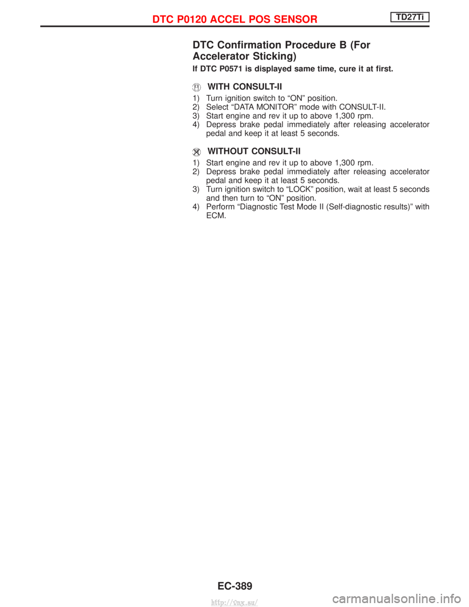
DTC Confirmation Procedure B (For
Accelerator Sticking)
If DTC P0571 is displayed same time, cure it at first.
WITH CONSULT-II
1) Turn ignition switch to ªONº position.
2) Select ªDATA MONITORº mode with CONSULT-II.
3) Start engine and rev it up to above 1,300 rpm.
4) Depress brake pedal immediately after releasing acceleratorpedal and keep it at least 5 seconds.
WITHOUT CONSULT-II
1) Start engine and rev it up to above 1,300 rpm.
2) Depress brake pedal immediately after releasing acceleratorpedal and keep it at least 5 seconds.
3) Turn ignition switch to ªLOCKº position, wait at least 5 seconds and then turn to ªONº position.
4) Perform ªDiagnostic Test Mode II (Self-diagnostic results)º with ECM.
DTC P0120 ACCEL POS SENSORTD27Ti
EC-389
http://vnx.su/
Page 815 of 1833
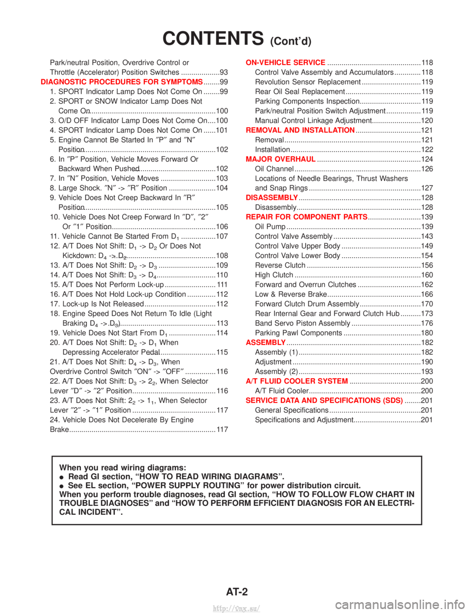
Park/neutral Position, Overdrive Control or
Throttle (Accelerator) Position Switches ...................93
DIAGNOSTIC PROCEDURES FOR SYMPTOMS ........99
1. SPORT Indicator Lamp Does Not Come On ........99
2. SPORT or SNOW Indicator Lamp Does Not Come On.................................................................100
3. O/D OFF Indicator Lamp Does Not Come On....100
4. SPORT Indicator Lamp Does Not Come On ......101
5. Engine Cannot Be Started In ²P² and ²N²
Position....................................................................102
6. In ²P² Position, Vehicle Moves Forward Or
Backward When Pushed.........................................102
7. In ²N² Position, Vehicle Moves ...........................103
8. Large Shock. ²N² ->²R² Position .......................104
9. Vehicle Does Not Creep Backward In ²R²
Position....................................................................105
10. Vehicle Does Not Creep Forward In ²D² ,²2²
Or ²1² Position.........................................................106
11. Vehicle Cannot Be Started From D
1.................107
12. A/T Does Not Shift: D
1-> D2Or Does Not
Kickdown: D
4-> D2..................................................108
13. A/T Does Not Shift: D
2-> D3............................109
14. A/T Does Not Shift: D
3-> D4............................. 110
15. A/T Does Not Perform Lock-up ......................... 111
16. A/T Does Not Hold Lock-up Condition .............. 112
17. Lock-up Is Not Released ................................... 112
18. Engine Speed Does Not Return To Idle (Light Braking D
4-> D3)..................................................... 113
19. Vehicle Does Not Start From D
1....................... 114
20. A/T Does Not Shift: D
2-> D1When
Depressing Accelerator Pedal................................. 115
21. A/T Does Not Shift: D
4-> D3, When
Overdrive Control Switch ²ON² ->²OFF² ............... 116
22. A/T Does Not Shift: D
3-> 22, When Selector
Lever ²D² ->²2² Position......................................... 116
23. A/T Does Not Shift: 2
2-> 11, When Selector
Lever ²2² ->²1² Position ......................................... 117
24. Vehicle Does Not Decelerate By Engine
Brake........................................................................\
117 ON-VEHICLE SERVICE
.............................................. 118
Control Valve Assembly and Accumulators ............. 118
Revolution Sensor Replacement ............................. 119
Rear Oil Seal Replacement ..................................... 119
Parking Components Inspection.............................. 119
Park/neutral Position Switch Adjustment ................. 119
Manual Control Linkage Adjustment........................120
REMOVAL AND INSTALLATION ................................121
Removal ...................................................................121
Installation ................................................................122
MAJOR OVERHAUL ...................................................124
Oil Channel ..............................................................126
Locations of Needle Bearings, Thrust Washers
and Snap Rings .......................................................127
DISASSEMBLY ............................................................128
Disassembly.............................................................128
REPAIR FOR COMPONENT PARTS ..........................139
Oil Pump ..................................................................139
Control Valve Assembly ...........................................143
Control Valve Upper Body .......................................149
Control Valve Lower Body .......................................154
Reverse Clutch ........................................................156
High Clutch ..............................................................160
Forward and Overrun Clutches ...............................162
Low & Reverse Brake..............................................166
Forward Clutch Drum Assembly ..............................170
Rear Internal Gear and Forward Clutch Hub ..........173
Band Servo Piston Assembly ..................................176
Parking Pawl Components ......................................180
ASSEMBLY ..................................................................182
Assembly (1) ............................................................182
Adjustment ...............................................................190
Assembly (2) ............................................................193
A/T FLUID COOLER SYSTEM ...................................200
A/T Fluid Cooler.......................................................200
SERVICE DATA AND SPECIFICATIONS (SDS) ........201
General Specifications .............................................201
Specifications and Adjustment.................................201
When you read wiring diagrams:
I Read GI section, ªHOW TO READ WIRING DIAGRAMSº.
I See EL section, ªPOWER SUPPLY ROUTINGº for power distribution circuit.
When you perform trouble diagnoses, read GI section, ªHOW TO FOLLOW FLOW CHART IN
TROUBLE DIAGNOSESº and ªHOW TO PERFORM EFFICIENT DIAGNOSIS FOR AN ELECTRI-
CAL INCIDENTº.
CONTENTS(Cont'd)
AT- 2
http://vnx.su/