fuel pump NISSAN TERRANO 2004 Service Repair Manual
[x] Cancel search | Manufacturer: NISSAN, Model Year: 2004, Model line: TERRANO, Model: NISSAN TERRANO 2004Pages: 1833, PDF Size: 53.42 MB
Page 8 of 1833
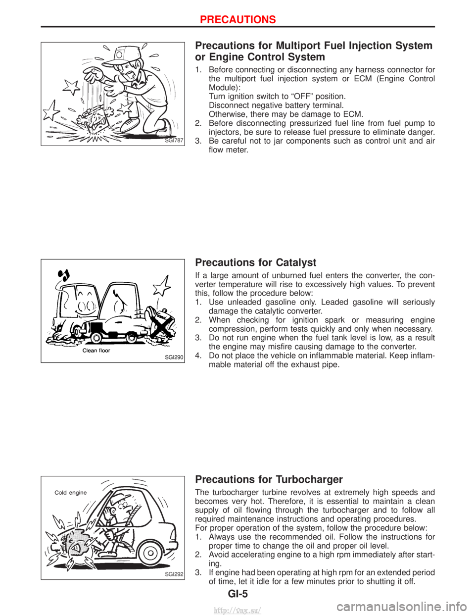
Precautions for Multiport Fuel Injection System
or Engine Control System
1. Before connecting or disconnecting any harness connector forthe multiport fuel injection system or ECM (Engine Control
Module):
Turn ignition switch to ªOFFº position.
Disconnect negative battery terminal.
Otherwise, there may be damage to ECM.
2. Before disconnecting pressurized fuel line from fuel pump to injectors, be sure to release fuel pressure to eliminate danger.
3. Be careful not to jar components such as control unit and air flow meter.
Precautions for Catalyst
If a large amount of unburned fuel enters the converter, the con-
verter temperature will rise to excessively high values. To prevent
this, follow the procedure below:
1. Use unleaded gasoline only. Leaded gasoline will seriouslydamage the catalytic converter.
2. When checking for ignition spark or measuring engine compression, perform tests quickly and only when necessary.
3. Do not run engine when the fuel tank level is low, as a result the engine may misfire causing damage to the converter.
4. Do not place the vehicle on inflammable material. Keep inflam- mable material off the exhaust pipe.
Precautions for Turbocharger
The turbocharger turbine revolves at extremely high speeds and
becomes very hot. Therefore, it is essential to maintain a clean
supply of oil flowing through the turbocharger and to follow all
required maintenance instructions and operating procedures.
For proper operation of the system, follow the procedure below:
1. Always use the recommended oil. Follow the instructions forproper time to change the oil and proper oil level.
2. Avoid accelerating engine to a high rpm immediately after start- ing.
3. If engine had been operating at high rpm for an extended period of time, let it idle for a few minutes prior to shutting it off.
SGI787
SGI290
SGI292
PRECAUTIONS
GI-5
http://vnx.su/
Page 39 of 1833
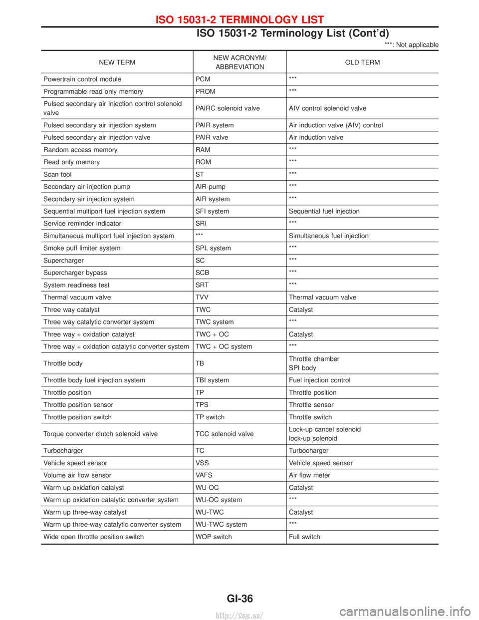
***: Not applicable
NEW TERMNEW ACRONYM/
ABBREVIATION OLD TERM
Powertrain control module PCM ***
Programmable read only memory PROM ***
Pulsed secondary air injection control solenoid
valve PAIRC solenoid valve AIV control solenoid valve
Pulsed secondary air injection system PAIR system Air induction valve (AIV) control
Pulsed secondary air injection valve PAIR valve Air induction valve
Random access memory RAM ***
Read only memory ROM ***
Scan tool ST ***
Secondary air injection pump AIR pump ***
Secondary air injection system AIR system ***
Sequential multiport fuel injection system SFI system Sequential fuel injection
Service reminder indicator SRI ***
Simultaneous multiport fuel injection system *** Simultaneous fuel injection
Smoke puff limiter system SPL system ***
Supercharger SC ***
Supercharger bypass SCB ***
System readiness test SRT ***
Thermal vacuum valve TVV Thermal vacuum valve
Three way catalyst TWC Catalyst
Three way catalytic converter system TWC system ***
Three way + oxidation catalyst TWC + OC Catalyst
Three way + oxidation catalytic converter system TWC + OC system ***
Throttle body TB Throttle chamber
SPI body
Throttle body fuel injection system TBI system Fuel injection control
Throttle position TP Throttle position
Throttle position sensor TPS Throttle sensor
Throttle position switch TP switch Throttle switch
Torque converter clutch solenoid valve TCC solenoid valve Lock-up cancel solenoid
lock-up solenoid
Turbocharger TC Turbocharger
Vehicle speed sensor VSS Vehicle speed sensor
Volume air flow sensor VAFS Air flow meter
Warm up oxidation catalyst WU-OC Catalyst
Warm up oxidation catalytic converter system WU-OC system ***
Warm up three-way catalyst WU-TWC Catalyst
Warm up three-way catalytic converter system WU-TWC system ***
Wide open throttle position switch WOP switch Full switch
ISO 15031-2 TERMINOLOGY LIST
ISO 15031-2 Terminology List (Cont'd)
GI-36
http://vnx.su/
Page 65 of 1833
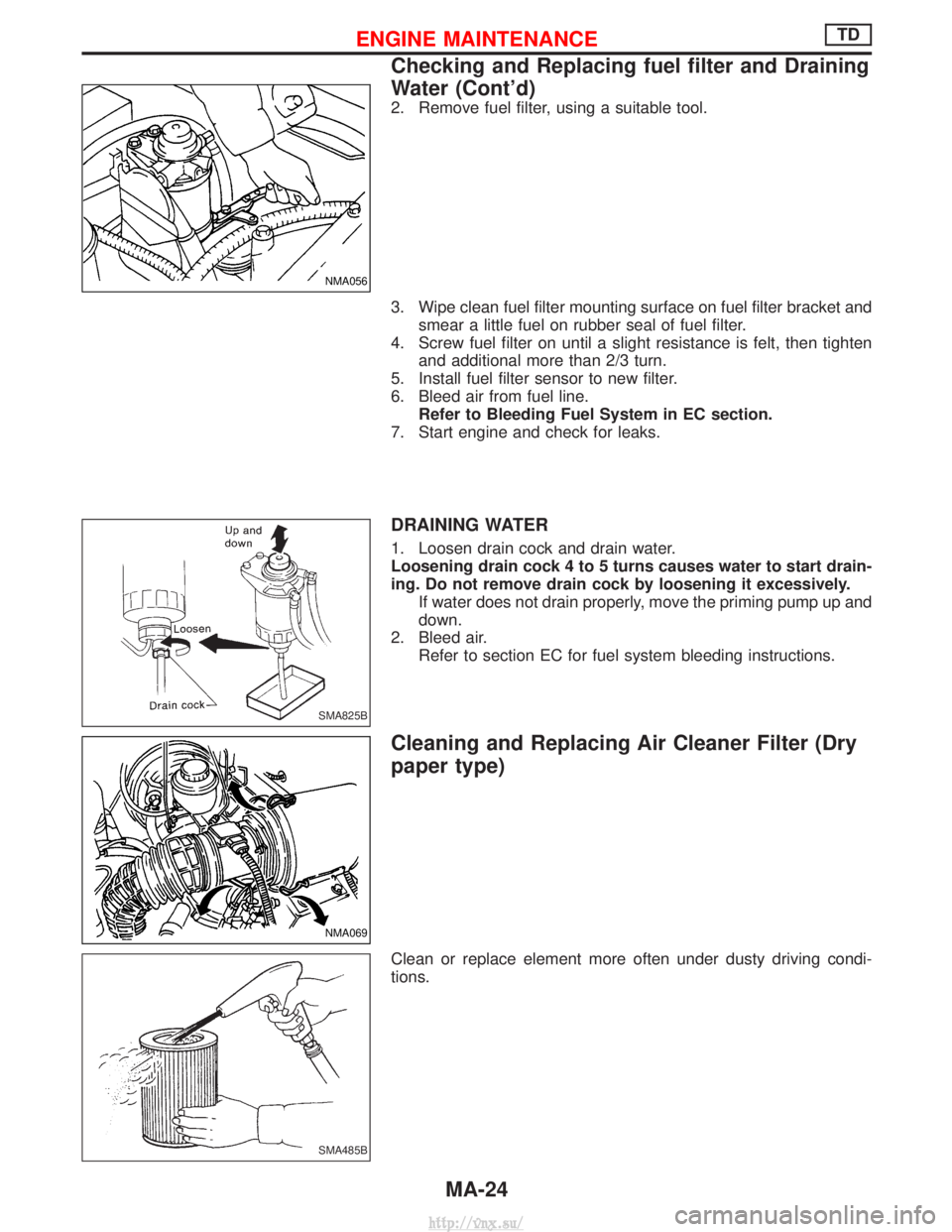
2. Remove fuel filter, using a suitable tool.
3. Wipe clean fuel filter mounting surface on fuel filter bracket andsmear a little fuel on rubber seal of fuel filter.
4. Screw fuel filter on until a slight resistance is felt, then tighten and additional more than 2/3 turn.
5. Install fuel filter sensor to new filter.
6. Bleed air from fuel line. Refer to Bleeding Fuel System in EC section.
7. Start engine and check for leaks.
DRAINING WATER
1. Loosen drain cock and drain water.
Loosening drain cock 4 to 5 turns causes water to start drain-
ing. Do not remove drain cock by loosening it excessively. If water does not drain properly, move the priming pump up and
down.
2. Bleed air. Refer to section EC for fuel system bleeding instructions.
Cleaning and Replacing Air Cleaner Filter (Dry
paper type)
Clean or replace element more often under dusty driving condi-
tions.
NMA056
SMA825B
NMA069
SMA485B
ENGINE MAINTENANCETD
Checking and Replacing fuel filter and Draining
Water (Cont'd)
MA-24
http://vnx.su/
Page 66 of 1833
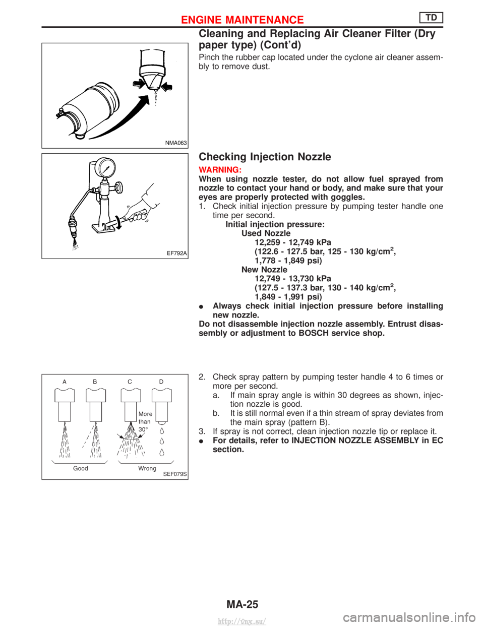
Pinch the rubber cap located under the cyclone air cleaner assem-
bly to remove dust.
Checking Injection Nozzle
WARNING:
When using nozzle tester, do not allow fuel sprayed from
nozzle to contact your hand or body, and make sure that your
eyes are properly protected with goggles.
1. Check initial injection pressure by pumping tester handle onetime per second.Initial injection pressure: Used Nozzle12,259 - 12,749 kPa
(122.6 - 127.5 bar, 125 - 130 kg/cm
2,
1,778 - 1,849 psi)
New Nozzle 12,749 - 13,730 kPa
(127.5 - 137.3 bar, 130 - 140 kg/cm
2,
1,849 - 1,991 psi)
I Always check initial injection pressure before installing
new nozzle.
Do not disassemble injection nozzle assembly. Entrust disas-
sembly or adjustment to BOSCH service shop.
2. Check spray pattern by pumping tester handle 4 to 6 times or more per second.
a. If main spray angle is within 30 degrees as shown, injec- tion nozzle is good.
b. It is still normal even if a thin stream of spray deviates from the main spray (pattern B).
3. If spray is not correct, clean injection nozzle tip or replace it.
I For details, refer to INJECTION NOZZLE ASSEMBLY in EC
section.
NMA063
EF792A
SEF079S
ENGINE MAINTENANCETD
Cleaning and Replacing Air Cleaner Filter (Dry
paper type) (Cont'd)
MA-25
http://vnx.su/
Page 75 of 1833
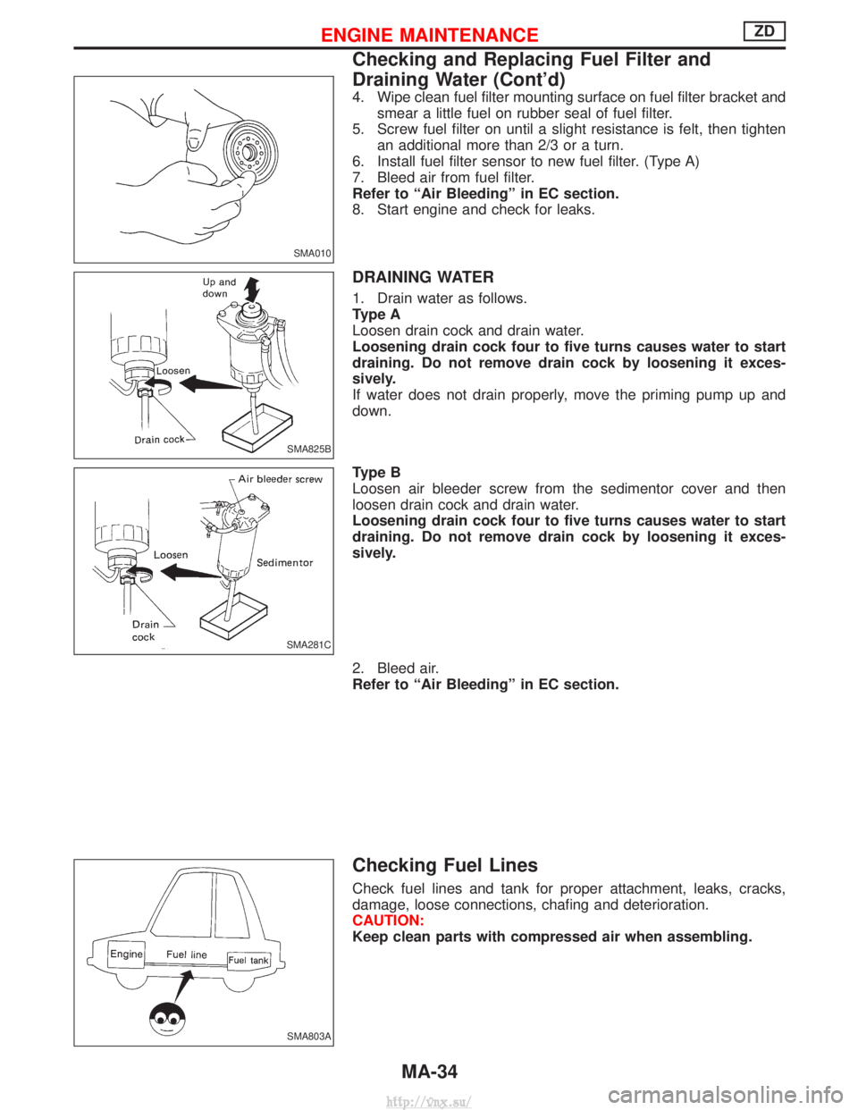
4. Wipe clean fuel filter mounting surface on fuel filter bracket andsmear a little fuel on rubber seal of fuel filter.
5. Screw fuel filter on until a slight resistance is felt, then tighten an additional more than 2/3 or a turn.
6. Install fuel filter sensor to new fuel filter. (Type A)
7. Bleed air from fuel filter.
Refer to ªAir Bleedingº in EC section.
8. Start engine and check for leaks.
DRAINING WATER
1. Drain water as follows.
Type A
Loosen drain cock and drain water.
Loosening drain cock four to five turns causes water to start
draining. Do not remove drain cock by loosening it exces-
sively.
If water does not drain properly, move the priming pump up and
down.
Type B
Loosen air bleeder screw from the sedimentor cover and then
loosen drain cock and drain water.
Loosening drain cock four to five turns causes water to start
draining. Do not remove drain cock by loosening it exces-
sively.
2. Bleed air.
Refer to ªAir Bleedingº in EC section.
Checking Fuel Lines
Check fuel lines and tank for proper attachment, leaks, cracks,
damage, loose connections, chafing and deterioration.
CAUTION:
Keep clean parts with compressed air when assembling.
SMA010
SMA825B
SMA281C
SMA803A
ENGINE MAINTENANCEZD
Checking and Replacing Fuel Filter and
Draining Water (Cont'd)
MA-34
http://vnx.su/
Page 101 of 1833
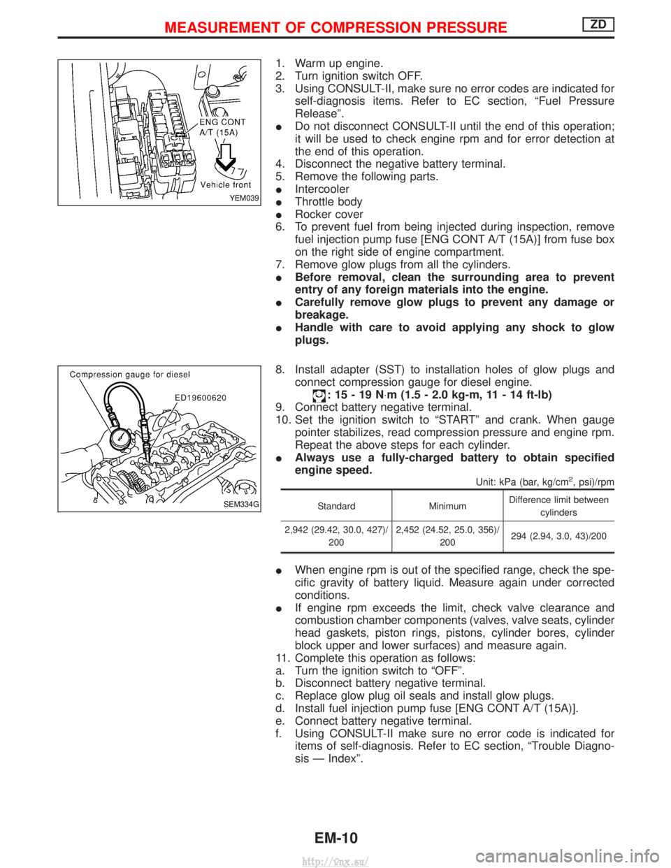
1. Warm up engine.
2. Turn ignition switch OFF.
3. Using CONSULT-II, make sure no error codes are indicated forself-diagnosis items. Refer to EC section, ªFuel Pressure
Releaseº.
I Do not disconnect CONSULT-II until the end of this operation;
it will be used to check engine rpm and for error detection at
the end of this operation.
4. Disconnect the negative battery terminal.
5. Remove the following parts.
I Intercooler
I Throttle body
I Rocker cover
6. To prevent fuel from being injected during inspection, remove fuel injection pump fuse [ENG CONT A/T (15A)] from fuse box
on the right side of engine compartment.
7. Remove glow plugs from all the cylinders.
I Before removal, clean the surrounding area to prevent
entry of any foreign materials into the engine.
I Carefully remove glow plugs to prevent any damage or
breakage.
I Handle with care to avoid applying any shock to glow
plugs.
8. Install adapter (SST) to installation holes of glow plugs and connect compression gauge for diesel engine.
:15-19N ×m (1.5 - 2.0 kg-m, 11 - 14 ft-lb)
9. Connect battery negative terminal.
10. Set the ignition switch to ªSTARTº and crank. When gauge pointer stabilizes, read compression pressure and engine rpm.
Repeat the above steps for each cylinder.
I Always use a fully-charged battery to obtain specified
engine speed.
Unit: kPa (bar, kg/cm2, psi)/rpm
Standard MinimumDifference limit between
cylinders
2,942 (29.42, 30.0, 427)/ 200 2,452 (24.52, 25.0, 356)/
200 294 (2.94, 3.0, 43)/200
I
When engine rpm is out of the specified range, check the spe-
cific gravity of battery liquid. Measure again under corrected
conditions.
I If engine rpm exceeds the limit, check valve clearance and
combustion chamber components (valves, valve seats, cylinder
head gaskets, piston rings, pistons, cylinder bores, cylinder
block upper and lower surfaces) and measure again.
11. Complete this operation as follows:
a. Turn the ignition switch to ªOFFº.
b. Disconnect battery negative terminal.
c. Replace glow plug oil seals and install glow plugs.
d. Install fuel injection pump fuse [ENG CONT A/T (15A)].
e. Connect battery negative terminal.
f. Using CONSULT-II make sure no error code is indicated for items of self-diagnosis. Refer to EC section, ªTrouble Diagno-
sis Ð Indexº.
YEM039
SEM334G
MEASUREMENT OF COMPRESSION PRESSUREZD
EM-10
http://vnx.su/
Page 117 of 1833
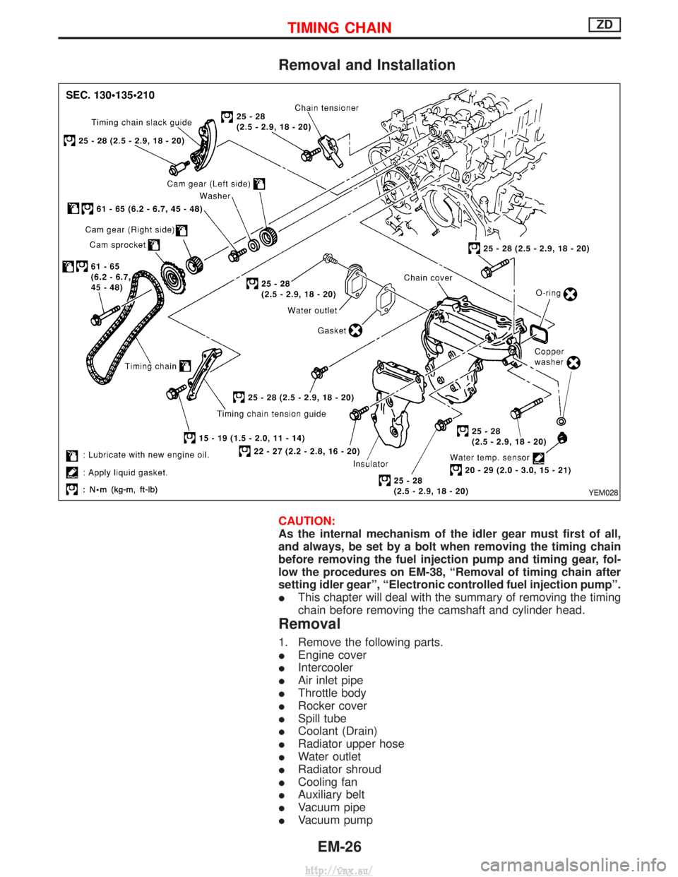
Removal and Installation
CAUTION:
As the internal mechanism of the idler gear must first of all,
and always, be set by a bolt when removing the timing chain
before removing the fuel injection pump and timing gear, fol-
low the procedures on EM-38, ªRemoval of timing chain after
setting idler gearº, ªElectronic controlled fuel injection pumpº.
IThis chapter will deal with the summary of removing the timing
chain before removing the camshaft and cylinder head.
Removal
1. Remove the following parts.
IEngine cover
I Intercooler
I Air inlet pipe
I Throttle body
I Rocker cover
I Spill tube
I Coolant (Drain)
I Radiator upper hose
I Water outlet
I Radiator shroud
I Cooling fan
I Auxiliary belt
I Vacuum pipe
I Vacuum pump
YEM028
TIMING CHAINZD
EM-26
http://vnx.su/
Page 132 of 1833
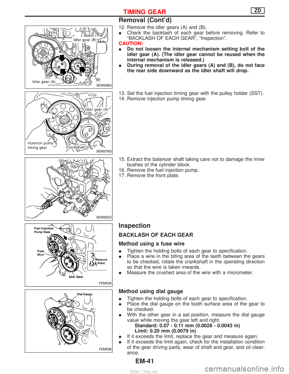
12. Remove the idler gears (A) and (B).
ICheck the backlash of each gear before removing. Refer to
ªBACKLASH OF EACH GEARº, ªInspectionº.
CAUTION:
I Do not loosen the internal mechanism setting bolt of the
idler gear (A). (The idler gear cannot be reused when the
internal mechanism is released.)
I During removal of the idler gears (A) and (B), do not face
the rear side downward as the idler shaft will drop.
13. Set the fuel injection timing gear with the pulley holder (SST).
14. Remove injection pump timing gear.
15. Extract the balancer shaft taking care not to damage the inner bushes of the cylinder block.
16. Remove the fuel injection pump.
17. Remove the front plate.
Inspection
BACKLASH OF EACH GEAR
Method using a fuse wire
I Tighten the holding bolts of each gear to specification.
I Place a wire in the biting area of the teeth between the gears
to be checked, rotate the crankshaft in the operating direction
so that the wire is taken inwards.
I Measure the crushed area of the wire with a micrometer.
Method using dial gauge
ITighten the holding bolts of each gear to specification.
I Place the dial gauge on the tooth surface area of the gear to
be checked.
I With the other gear in a set position, measure the dial gauge
value while moving the gear left and right.
Standard: 0.07 - 0.11 mm (0.0028 - 0.0043 in)
Limit: 0.20 mm (0.0079 in)
I If it exceeds the limit, replace the gear and measure again.
I If it exceeds the limit again, check for the installation condition
of the gear driving parts, wear of shaft and gear, and oil clear-
ance.
SEM348G
SEM378G
SEM352G
FEM035
FEM036
TIMING GEARZD
Removal (Cont'd)
EM-41
http://vnx.su/
Page 137 of 1833
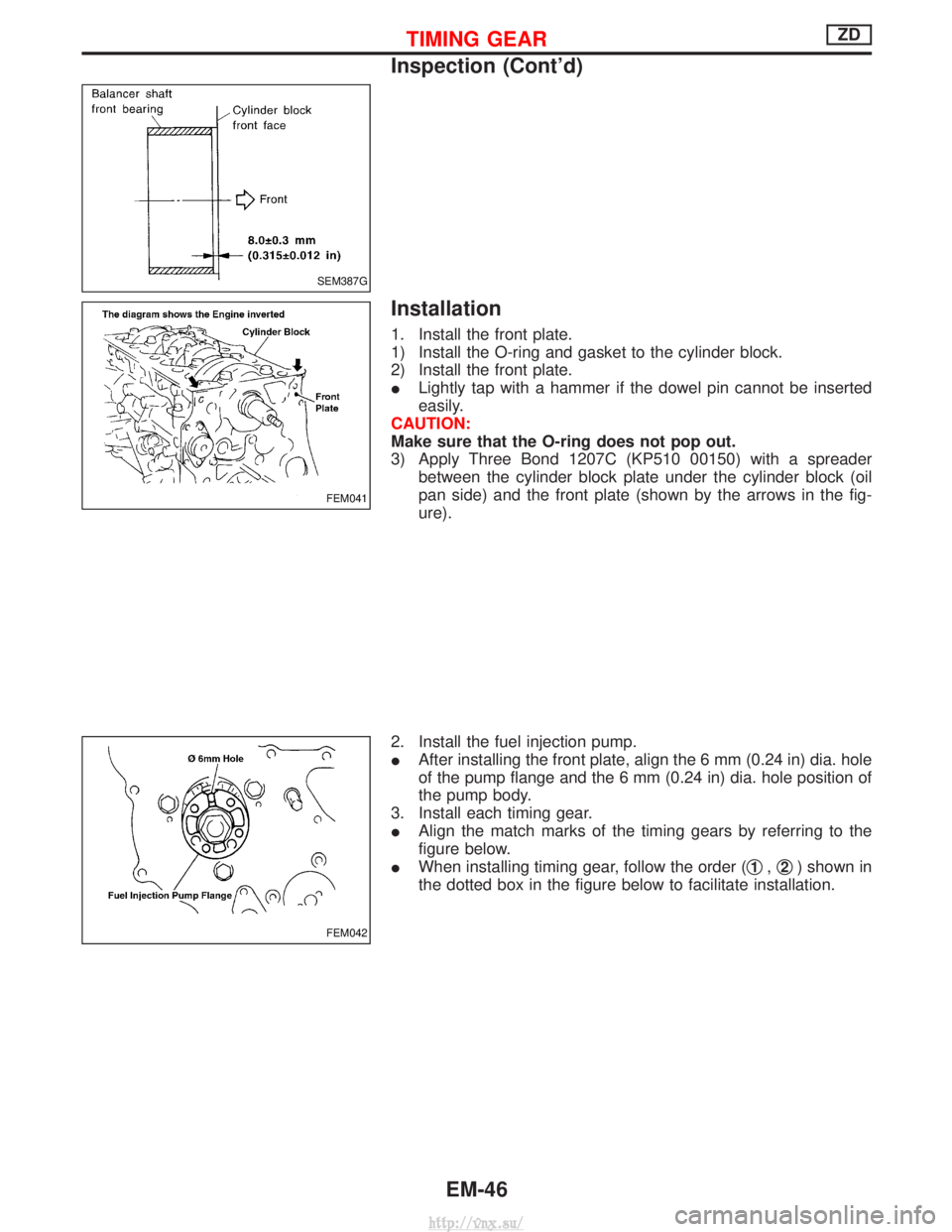
Installation
1. Install the front plate.
1) Install the O-ring and gasket to the cylinder block.
2) Install the front plate.
ILightly tap with a hammer if the dowel pin cannot be inserted
easily.
CAUTION:
Make sure that the O-ring does not pop out.
3) Apply Three Bond 1207C (KP510 00150) with a spreader between the cylinder block plate under the cylinder block (oil
pan side) and the front plate (shown by the arrows in the fig-
ure).
2. Install the fuel injection pump.
I After installing the front plate, align the 6 mm (0.24 in) dia. hole
of the pump flange and the 6 mm (0.24 in) dia. hole position of
the pump body.
3. Install each timing gear.
I Align the match marks of the timing gears by referring to the
figure below.
I When installing timing gear, follow the order ( q
1,q2) shown in
the dotted box in the figure below to facilitate installation.
SEM387G
FEM041
FEM042
TIMING GEARZD
Inspection (Cont'd)
EM-46
http://vnx.su/
Page 159 of 1833
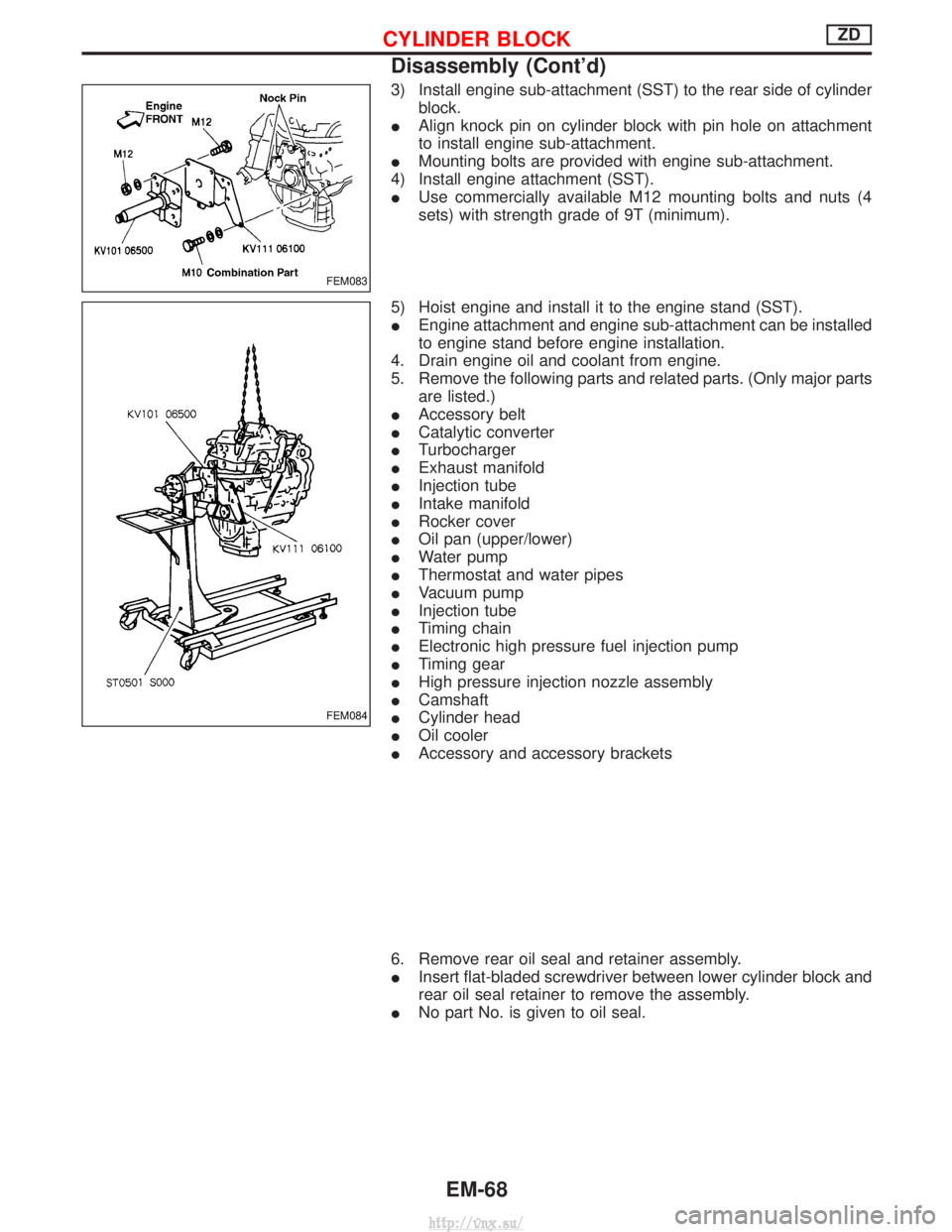
3) Install engine sub-attachment (SST) to the rear side of cylinderblock.
I Align knock pin on cylinder block with pin hole on attachment
to install engine sub-attachment.
I Mounting bolts are provided with engine sub-attachment.
4) Install engine attachment (SST).
I Use commercially available M12 mounting bolts and nuts (4
sets) with strength grade of 9T (minimum).
5) Hoist engine and install it to the engine stand (SST).
I Engine attachment and engine sub-attachment can be installed
to engine stand before engine installation.
4. Drain engine oil and coolant from engine.
5. Remove the following parts and related parts. (Only major parts are listed.)
I Accessory belt
I Catalytic converter
I Turbocharger
I Exhaust manifold
I Injection tube
I Intake manifold
I Rocker cover
I Oil pan (upper/lower)
I Water pump
I Thermostat and water pipes
I Vacuum pump
I Injection tube
I Timing chain
I Electronic high pressure fuel injection pump
I Timing gear
I High pressure injection nozzle assembly
I Camshaft
I Cylinder head
I Oil cooler
I Accessory and accessory brackets
6. Remove rear oil seal and retainer assembly.
I Insert flat-bladed screwdriver between lower cylinder block and
rear oil seal retainer to remove the assembly.
I No part No. is given to oil seal.
FEM083
FEM084
CYLINDER BLOCKZD
Disassembly (Cont'd)
EM-68
http://vnx.su/