glow plug NISSAN TERRANO 2004 Service Repair Manual
[x] Cancel search | Manufacturer: NISSAN, Model Year: 2004, Model line: TERRANO, Model: NISSAN TERRANO 2004Pages: 1833, PDF Size: 53.42 MB
Page 98 of 1833
Tool nameDescription
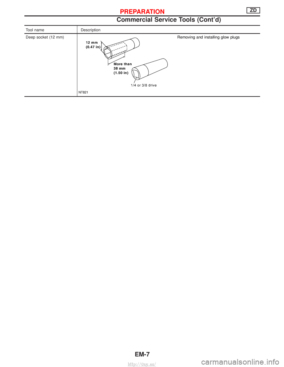
Deep socket (12 mm)
NT821
Removing and installing glow plugs
PREPARATIONZD
Commercial Service Tools (Cont'd)
EM-7
http://vnx.su/
Page 101 of 1833
1. Warm up engine.
2. Turn ignition switch OFF.
3. Using CONSULT-II, make sure no error codes are indicated forself-diagnosis items. Refer to EC section, ªFuel Pressure
Releaseº.
I Do not disconnect CONSULT-II until the end of this operation;
it will be used to check engine rpm and for error detection at
the end of this operation.
4. Disconnect the negative battery terminal.
5. Remove the following parts.
I Intercooler
I Throttle body
I Rocker cover
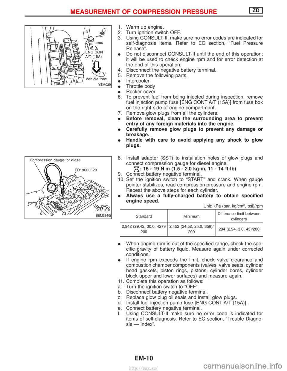
6. To prevent fuel from being injected during inspection, remove fuel injection pump fuse [ENG CONT A/T (15A)] from fuse box
on the right side of engine compartment.
7. Remove glow plugs from all the cylinders.
I Before removal, clean the surrounding area to prevent
entry of any foreign materials into the engine.
I Carefully remove glow plugs to prevent any damage or
breakage.
I Handle with care to avoid applying any shock to glow
plugs.
8. Install adapter (SST) to installation holes of glow plugs and connect compression gauge for diesel engine.
:15-19N ×m (1.5 - 2.0 kg-m, 11 - 14 ft-lb)
9. Connect battery negative terminal.
10. Set the ignition switch to ªSTARTº and crank. When gauge pointer stabilizes, read compression pressure and engine rpm.
Repeat the above steps for each cylinder.
I Always use a fully-charged battery to obtain specified
engine speed.
Unit: kPa (bar, kg/cm2, psi)/rpm
Standard MinimumDifference limit between
cylinders
2,942 (29.42, 30.0, 427)/ 200 2,452 (24.52, 25.0, 356)/
200 294 (2.94, 3.0, 43)/200
I
When engine rpm is out of the specified range, check the spe-
cific gravity of battery liquid. Measure again under corrected
conditions.
I If engine rpm exceeds the limit, check valve clearance and
combustion chamber components (valves, valve seats, cylinder
head gaskets, piston rings, pistons, cylinder bores, cylinder
block upper and lower surfaces) and measure again.
11. Complete this operation as follows:
a. Turn the ignition switch to ªOFFº.
b. Disconnect battery negative terminal.
c. Replace glow plug oil seals and install glow plugs.
d. Install fuel injection pump fuse [ENG CONT A/T (15A)].
e. Connect battery negative terminal.
f. Using CONSULT-II make sure no error code is indicated for items of self-diagnosis. Refer to EC section, ªTrouble Diagno-
sis Ð Indexº.
YEM039
SEM334G
MEASUREMENT OF COMPRESSION PRESSUREZD
EM-10
http://vnx.su/
Page 111 of 1833
Removal and Installation
REMOVAL
1. Remove the following parts.
IEngine cover
I Intercooler
I Air inlet pipe
I Throttle body
I Wires, harnesses, tubes and pipes
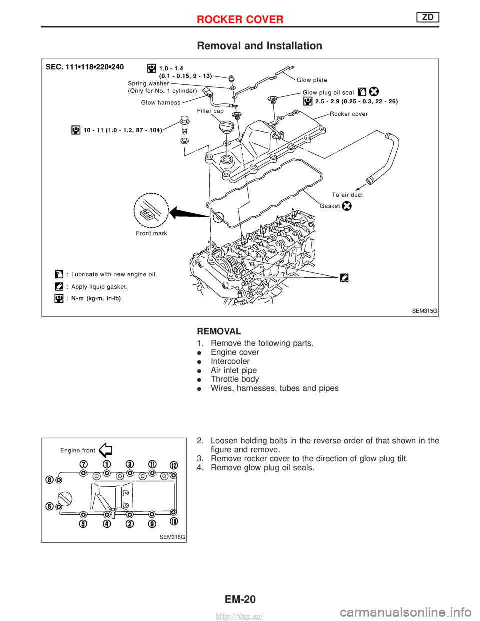
2. Loosen holding bolts in the reverse order of that shown in the figure and remove.
3. Remove rocker cover to the direction of glow plug tilt.
4. Remove glow plug oil seals.
SEM315G
SEM316G
ROCKER COVERZD
EM-20
http://vnx.su/
Page 112 of 1833
INSTALLATION
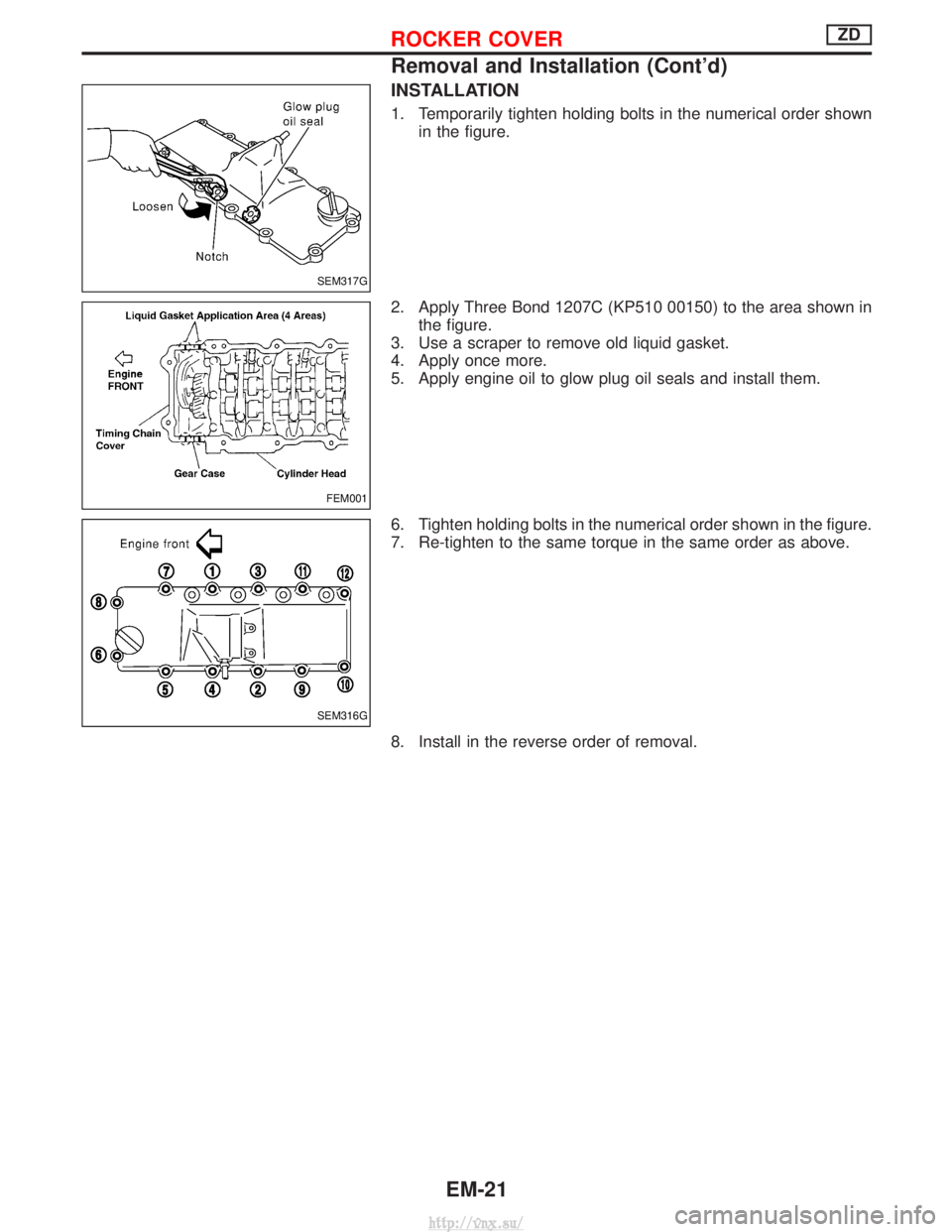
1. Temporarily tighten holding bolts in the numerical order shownin the figure.
2. Apply Three Bond 1207C (KP510 00150) to the area shown in the figure.
3. Use a scraper to remove old liquid gasket.
4. Apply once more.
5. Apply engine oil to glow plug oil seals and install them.
6. Tighten holding bolts in the numerical order shown in the figure.
7. Re-tighten to the same torque in the same order as above.
8. Install in the reverse order of removal.
SEM317G
FEM001
SEM316G
ROCKER COVERZD
Removal and Installation (Cont'd)
EM-21
http://vnx.su/
Page 144 of 1833
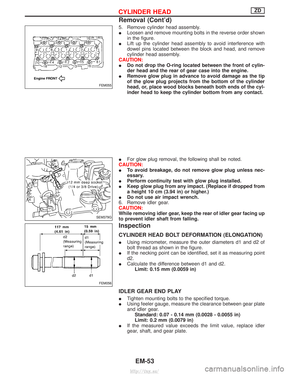
5. Remove cylinder head assembly.
ILoosen and remove mounting bolts in the reverse order shown
in the figure.
I Lift up the cylinder head assembly to avoid interference with
dowel pins located between the block and head, and remove
cylinder head assembly.
CAUTION:
I Do not drop the O-ring located between the front of cylin-
der head and the rear of gear case into the engine.
I Remove glow plug in advance to avoid damage as the tip
of the glow plug projects from the bottom of the cylinder
head, or, place wood blocks beneath both ends of the cyl-
inder head to keep the cylinder bottom from any contact.
I For glow plug removal, the following shall be noted.
CAUTION:
I To avoid breakage, do not remove glow plug unless nec-
essary.
I Perform continuity test with glow plug installed.
I Keep glow plug from any impact. (Replace if dropped from
a height 10 cm (3.94 in) or higher.)
I Do not use air impact wrench.
6. Remove idler gear.
CAUTION:
While removing idler gear, keep the rear of idler gear facing up
to prevent idler shaft from falling.
Inspection
CYLINDER HEAD BOLT DEFORMATION (ELONGATION)
I Using micrometer, measure the outer diameters d1 and d2 of
bolt thread as shown in the figure.
I If the necking point can be identified, set it as measuring point
d2.
I Calculate the difference between d1 and d2.
Limit: 0.15 mm (0.0059 in)
IDLER GEAR END PLAY
I Tighten mounting bolts to the specified torque.
I Using feeler gauge, measure the clearance between gear plate
and idler gear.
Standard: 0.07 - 0.14 mm (0.0028 - 0.0055 in)
Limit: 0.2 mm (0.0079 in)
I If the measured value exceeds the limit value, replace idler
gear, shaft, and gear plate.
FEM055
SEM379G
FEM056
CYLINDER HEADZD
Removal (Cont'd)
EM-53
http://vnx.su/
Page 147 of 1833
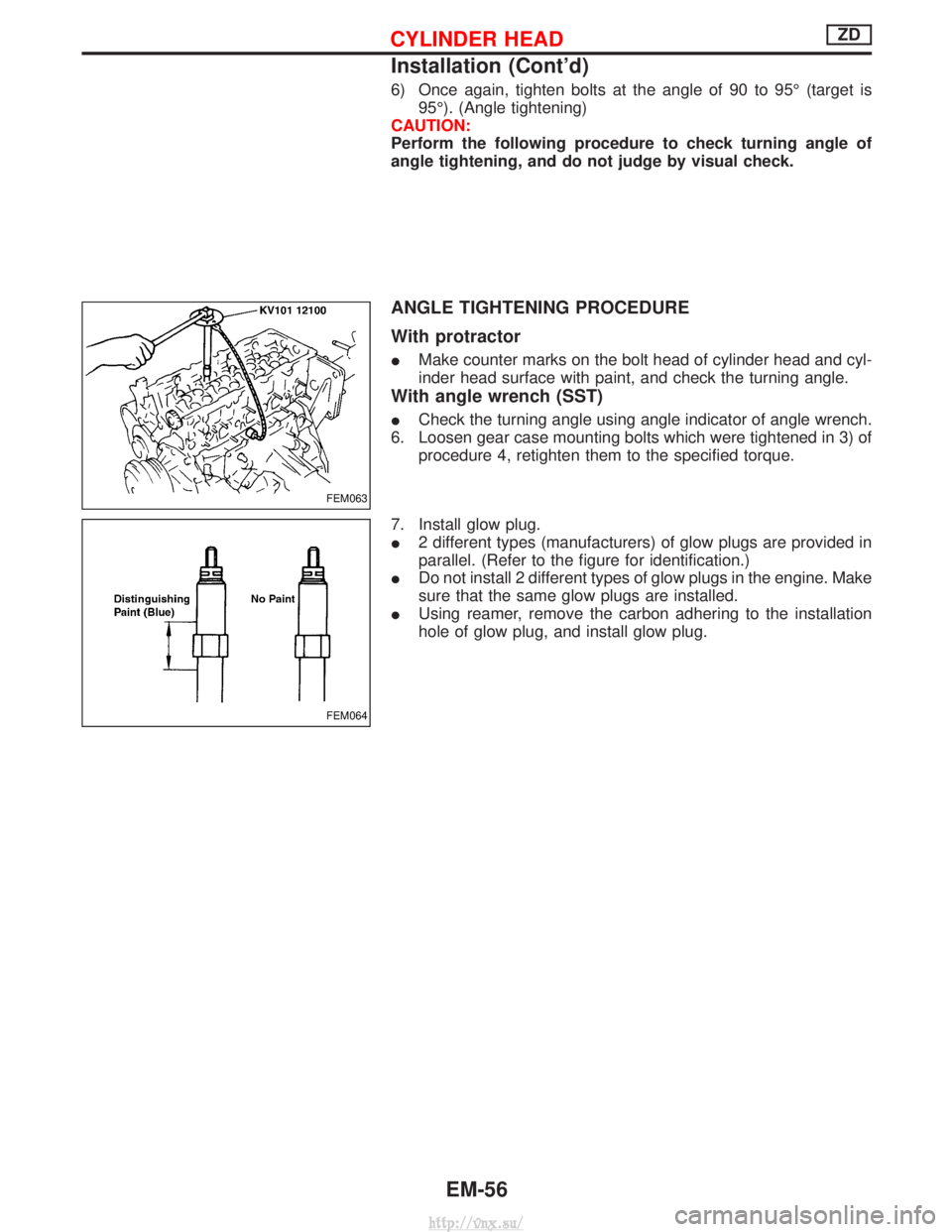
6) Once again, tighten bolts at the angle of 90 to 95É (target is95É). (Angle tightening)
CAUTION:
Perform the following procedure to check turning angle of
angle tightening, and do not judge by visual check.
ANGLE TIGHTENING PROCEDURE
With protractor
I Make counter marks on the bolt head of cylinder head and cyl-
inder head surface with paint, and check the turning angle.
With angle wrench (SST)
ICheck the turning angle using angle indicator of angle wrench.
6. Loosen gear case mounting bolts which were tightened in 3) of procedure 4, retighten them to the specified torque.
7. Install glow plug.
I 2 different types (manufacturers) of glow plugs are provided in
parallel. (Refer to the figure for identification.)
I Do not install 2 different types of glow plugs in the engine. Make
sure that the same glow plugs are installed.
I Using reamer, remove the carbon adhering to the installation
hole of glow plug, and install glow plug.
FEM063
FEM064
CYLINDER HEADZD
Installation (Cont'd)
EM-56
http://vnx.su/
Page 189 of 1833
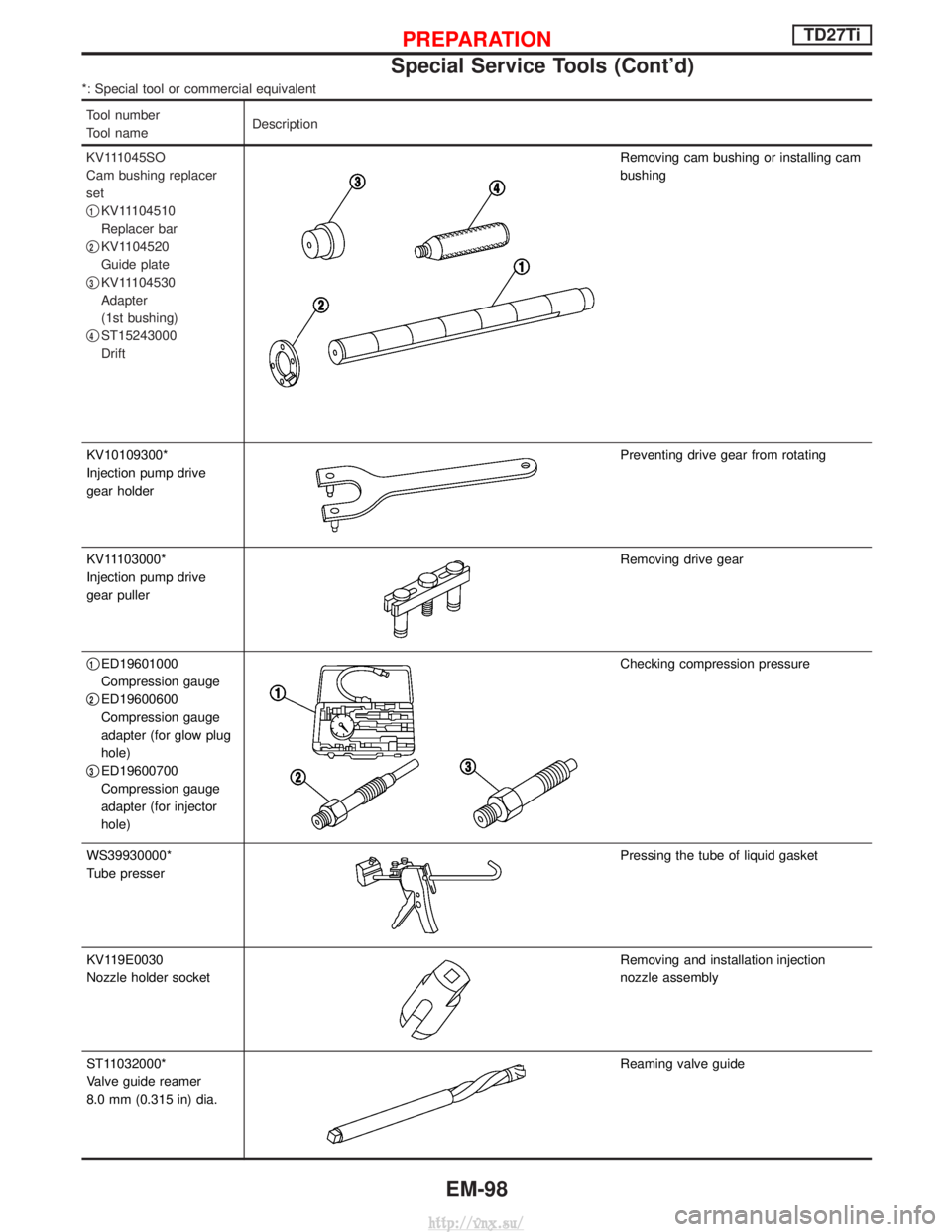
*: Special tool or commercial equivalent
Tool number
Tool nameDescription
KV111045SO
Cam bushing replacer
set
q
1KV11104510
Replacer bar
q
2KV1104520
Guide plate
q
3KV11104530
Adapter
(1st bushing)
q
4ST15243000
Drift
Removing cam bushing or installing cam
bushing
KV10109300*
Injection pump drive
gear holder
Preventing drive gear from rotating
KV11103000*
Injection pump drive
gear puller
Removing drive gear
q
1ED19601000
Compression gauge
q
2ED19600600
Compression gauge
adapter (for glow plug
hole)
q
3ED19600700
Compression gauge
adapter (for injector
hole)
Checking compression pressure
WS39930000*
Tube presser
Pressing the tube of liquid gasket
KV119E0030
Nozzle holder socket
Removing and installation injection
nozzle assembly
ST11032000*
Valve guide reamer
8.0 mm (0.315 in) dia.
Reaming valve guide
PREPARATIONTD27Ti
Special Service Tools (Cont'd)
EM-98
http://vnx.su/
Page 194 of 1833
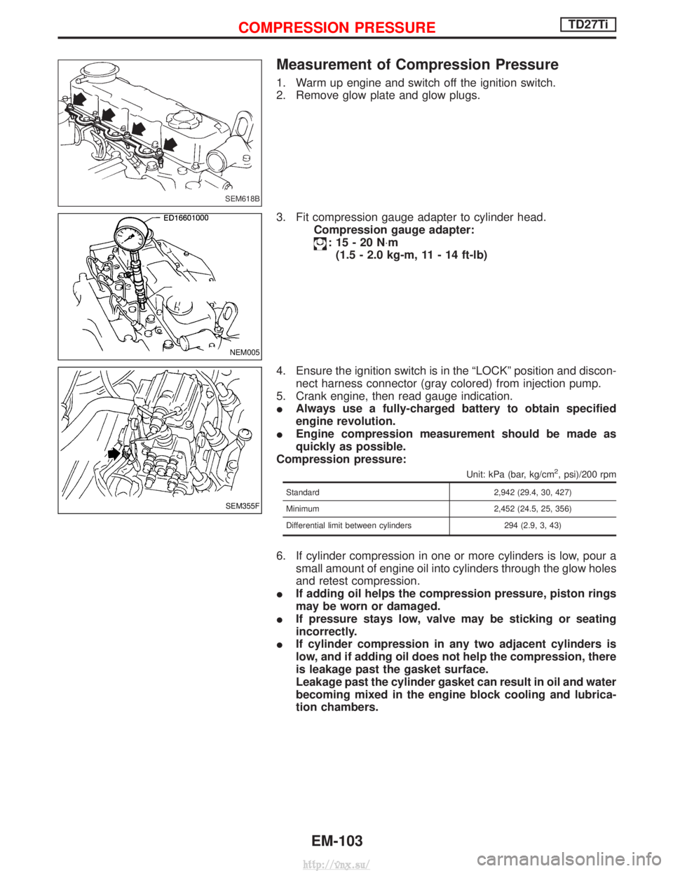
Measurement of Compression Pressure
1. Warm up engine and switch off the ignition switch.
2. Remove glow plate and glow plugs.
3. Fit compression gauge adapter to cylinder head.Compression gauge adapter:
:15-20N ×m
(1.5 - 2.0 kg-m, 11 - 14 ft-lb)
4. Ensure the ignition switch is in the ªLOCKº position and discon- nect harness connector (gray colored) from injection pump.
5. Crank engine, then read gauge indication.
I Always use a fully-charged battery to obtain specified
engine revolution.
I Engine compression measurement should be made as
quickly as possible.
Compression pressure:
Unit: kPa (bar, kg/cm2, psi)/200 rpm
Standard 2,942 (29.4, 30, 427)
Minimum 2,452 (24.5, 25, 356)
Differential limit between cylinders 294 (2.9, 3, 43)
6. If cylinder compression in one or more cylinders is low, pour a small amount of engine oil into cylinders through the glow holes
and retest compression.
I If adding oil helps the compression pressure, piston rings
may be worn or damaged.
I If pressure stays low, valve may be sticking or seating
incorrectly.
I If cylinder compression in any two adjacent cylinders is
low, and if adding oil does not help the compression, there
is leakage past the gasket surface.
Leakage past the cylinder gasket can result in oil and water
becoming mixed in the engine block cooling and lubrica-
tion chambers.
SEM618B
NEM005
SEM355F
COMPRESSION PRESSURETD27Ti
EM-103
http://vnx.su/
Page 195 of 1833
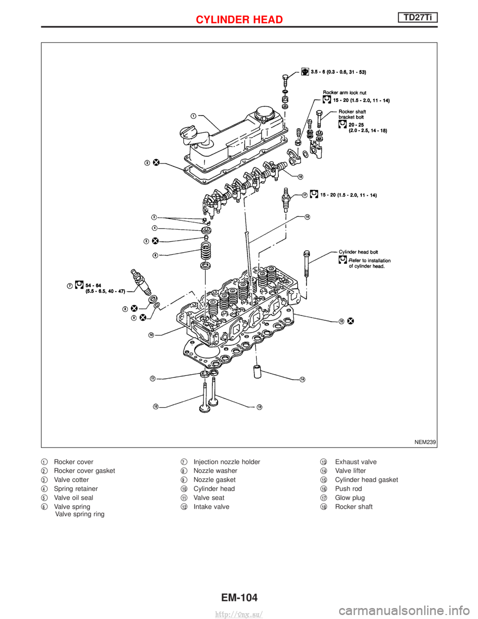
q1Rocker cover
q
2Rocker cover gasket
q
3Valve cotter
q
4Spring retainer
q
5Valve oil seal
q
6Valve spring Valve spring ring q
7Injection nozzle holder
q
8Nozzle washer
q
9Nozzle gasket
q
10Cylinder head
q
11Valve seat
q
12Intake valve q
13Exhaust valve
q
14Valve lifter
q
15Cylinder head gasket
q
16Push rod
q
17Glow plug
q
18Rocker shaft
NEM239
CYLINDER HEADTD27Ti
EM-104
http://vnx.su/
Page 197 of 1833
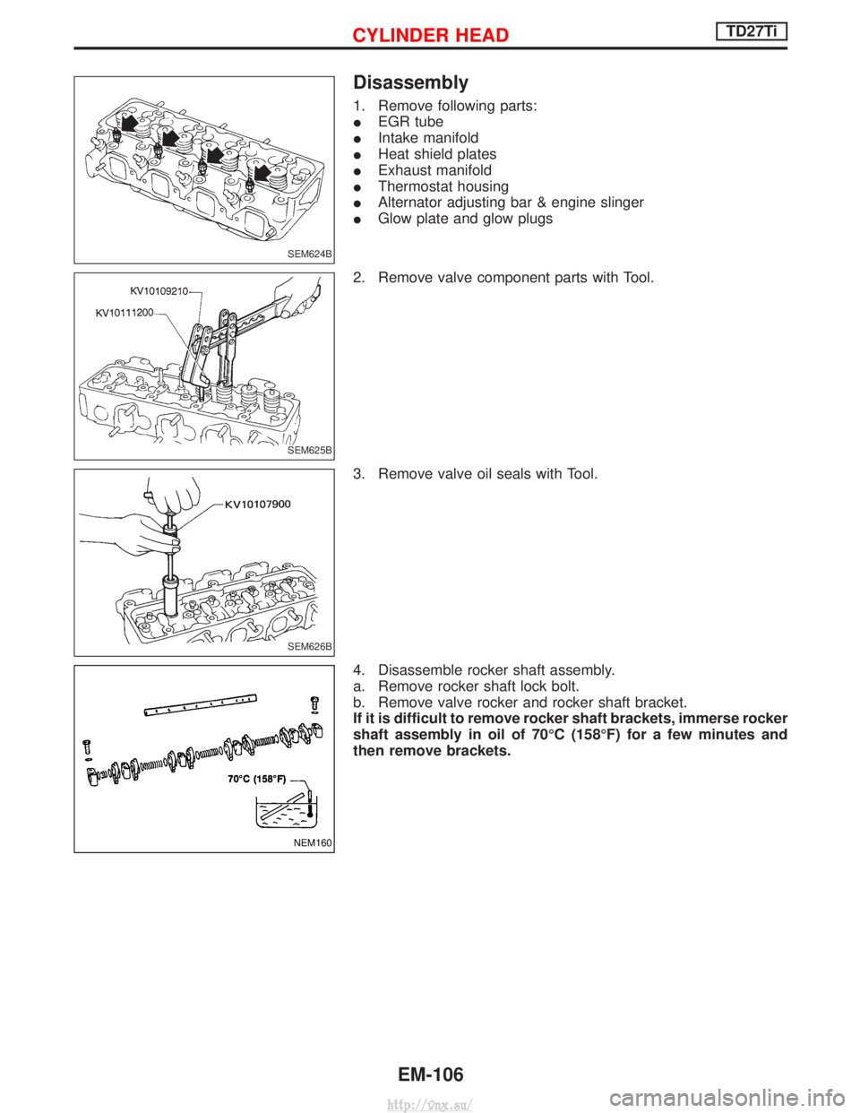
Disassembly
1. Remove following parts:
IEGR tube
I Intake manifold
I Heat shield plates
I Exhaust manifold
I Thermostat housing
I Alternator adjusting bar & engine slinger
I Glow plate and glow plugs
2. Remove valve component parts with Tool.
3. Remove valve oil seals with Tool.
4. Disassemble rocker shaft assembly.
a. Remove rocker shaft lock bolt.
b. Remove valve rocker and rocker shaft bracket.
If it is difficult to remove rocker shaft brackets, immerse rocker
shaft assembly in oil of 70ÉC (158ÉF) for a few minutes and
then remove brackets.
SEM624B
SEM625B
SEM626B
NEM160
CYLINDER HEADTD27Ti
EM-106
http://vnx.su/