check engine NISSAN TERRANO 2004 Service Repair Manual
[x] Cancel search | Manufacturer: NISSAN, Model Year: 2004, Model line: TERRANO, Model: NISSAN TERRANO 2004Pages: 1833, PDF Size: 53.42 MB
Page 4 of 1833
GENERAL INFORMATIONSECTION
GI
CONTENTS
PRECAUTIONS ...............................................................2
Supplemental Restraint System (SRS) ²AIR
BAG² and²SEAT BELT PRE-TENSIONER²
(Dual Air Bag System) .................................................3
Precautions for NATS ..................................................4
Precautions for Multiport Fuel Injection System
or Engine Control System ...........................................5
Precautions for Catalyst ..............................................5
Precautions for Turbocharger ......................................5
Precautions for Fuel ....................................................6
Precautions for Engine Oils .........................................6
HOW TO USE THIS MANUAL ........................................8
HOW TO READ WIRING DIAGRAMS ..........................10
Sample/Wiring Diagram - EXAMPL - ........................10
Description .................................................................12
HOW TO CHECK TERMINAL .......................................19
How to Probe Connectors .........................................19
How to Check Enlarged Contact Spring of
Terminal .....................................................................20
Waterproof Connector Inspection ..............................21
Terminal Lock Inspection ...........................................21
HOW TO PERFORM EFFICIENT DIAGNOSIS FOR
AN ELECTRICAL INCIDENT ........................................22 Work Flow ..................................................................22
Incident Simulation Tests ...........................................23
HOW TO FOLLOW FLOW CHART IN TROUBLE
DIAGNOSES ..................................................................25
CONSULT-II CHECKING SYSTEM ...............................26
Function and System Application ..............................26
Nickel Metal Hydride Battery Replacement...............26
Checking Equipment..................................................26
IDENTIFICATION INFORMATION .................................27
Model Variation ..........................................................27
Identification Number .................................................28
Dimensions ................................................................30
Wheels and Tires .......................................................30
LIFTING POINTS AND TOW TRUCK TOWING ...........31
Garage Jack and Safety Stand .................................31
Screw Jack ................................................................31
4-pole Lift ...................................................................32
Tow Truck Towing ......................................................32
ISO 15031-2 TERMINOLOGY LIST ..............................34
ISO 15031-2 Terminology List ...................................34
TIGHTENING TORQUE OF STANDARD BOLTS ........37
http://vnx.su/
Page 8 of 1833
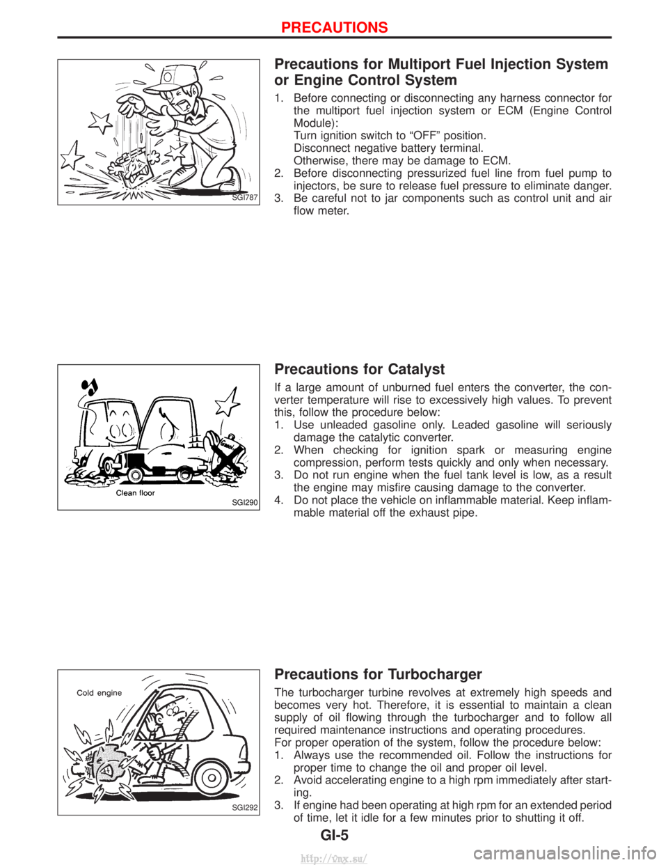
Precautions for Multiport Fuel Injection System
or Engine Control System
1. Before connecting or disconnecting any harness connector forthe multiport fuel injection system or ECM (Engine Control
Module):
Turn ignition switch to ªOFFº position.
Disconnect negative battery terminal.
Otherwise, there may be damage to ECM.
2. Before disconnecting pressurized fuel line from fuel pump to injectors, be sure to release fuel pressure to eliminate danger.
3. Be careful not to jar components such as control unit and air flow meter.
Precautions for Catalyst
If a large amount of unburned fuel enters the converter, the con-
verter temperature will rise to excessively high values. To prevent
this, follow the procedure below:
1. Use unleaded gasoline only. Leaded gasoline will seriouslydamage the catalytic converter.
2. When checking for ignition spark or measuring engine compression, perform tests quickly and only when necessary.
3. Do not run engine when the fuel tank level is low, as a result the engine may misfire causing damage to the converter.
4. Do not place the vehicle on inflammable material. Keep inflam- mable material off the exhaust pipe.
Precautions for Turbocharger
The turbocharger turbine revolves at extremely high speeds and
becomes very hot. Therefore, it is essential to maintain a clean
supply of oil flowing through the turbocharger and to follow all
required maintenance instructions and operating procedures.
For proper operation of the system, follow the procedure below:
1. Always use the recommended oil. Follow the instructions forproper time to change the oil and proper oil level.
2. Avoid accelerating engine to a high rpm immediately after start- ing.
3. If engine had been operating at high rpm for an extended period of time, let it idle for a few minutes prior to shutting it off.
SGI787
SGI290
SGI292
PRECAUTIONS
GI-5
http://vnx.su/
Page 9 of 1833
Precautions for Fuel
DIESEL ENGINE*:
Diesel fuel of at least 50 cetane for ZD30DDTi engine.
* If two types of diesel fuel are available, use summer or winterfuel properly according to the following temperature conditions.
I Above þ7ÉC (20ÉF) ... Summer type diesel fuel.
I Below þ7ÉC (20ÉF) ... Winter type diesel fuel.
CAUTION:
I Do not use home heating oil, gasoline, or other alternate
fuels in your diesel engine. The use of those can cause
engine damage.
I Do not use summer fuel at temperature below þ7ÉC (20ÉF).
The cold temperature will cause wax to form in the fuel. As
a result, it may prevent the engine from running smoothly.
I Do not add gasoline or other alternate fuels to diesel fuel.
Precautions for Engine Oils
Prolonged and repeated contact with mineral oil will result in the
removal of natural fats from the skin, leading to dryness, irritation
and dermatitis. In addition, used engine oil contains potentially
harmful contaminants which may cause skin cancer. Adequate
means of skin protection and washing facilities must be provided.
HEALTH PROTECTION PRECAUTIONS
1. Avoid prolonged and repeated contact with oils, particularly
used engine oils.
2. Wear protective clothing, including impervious gloves where practicable.
3. Do not put oily rags in pockets.
4. Avoid contaminating clothes, particularly underwear, with oil.
5. Heavily soiled clothing and oil-impregnated footwear should not be worn. Overalls must be cleaned regularly.
6. First Aid treatment should be obtained immediately for open cuts and wounds.
7. Use barrier creams, applying them before each work period, to help the removal of oil from the skin.
8. Wash with soap and water to ensure all oil is removed (skin cleansers and nail brushes will help). Preparations containing
lanolin replace the natural skin oils which have been removed.
9. Do not use petrol, kerosine, diesel fuel, gas oil, thinners or sol- vents for cleaning skin.
10. If skin disorders develop, obtain medical advice without delay.
11. Where practicable, degrease components prior to handling.
12. Where there is a risk of eye contact, eye protection should be worn, for example, chemical goggles or face shields; in addition
an eye wash facility should be provided.
(For the United Kingdom, see also HSE Cautionary Notice SHW
397 ªEffects of Mineral Oil on the Skinº.)
ENVIRONMENTAL PROTECTION PRECAUTIONS
Burning used engine oil in small space heaters or boilers can be
recommended only for units of approved design. The heating sys-
tem must meet the requirements of HM Inspectorate of Pollution for
small burners of less than 0.4 MW. If in doubt check with the
appropriate local authority and/or manufacturer of the approved
appliance.
PRECAUTIONS
GI-6
http://vnx.su/
Page 12 of 1833
7. The followingSYMBOLS AND ABBREVIATIONS are used:
,: Tightening torque
: Should be lubricated with grease.
Unless otherwise indicated, use rec-
ommended multi-purpose grease.
: Should be lubricated with oil.
: Sealing point
: Checking point
: Always replace after every disassem- bly.
L.H., R.H.: Left-Hand, Right-Hand
FR, RR : Front, Rear
2WD : 2-Wheel Drive
4WD : 4-Wheel Drive
qP: Apply petroleum jelly.
: Apply A.T.F.
A.T.F. : Automatic Transmission Fluid
H : Select with proper thickness.
I : Adjustment is required.
M/T : Manual Transaxle/Transmission
A/C : Air Conditioner
P/S : Power Steering
S.S.T. : Special Service Tools
S.D.S. : Service Data and Specifications
SAE : Society of Automotive Engineers, Inc.
L.H.D. : Left-Hand Drive
R.H.D. : Right-Hand Drive
8. The UNITSgiven in this manual are primarily expressed as the SI UNIT (International System of Unit),
and alternatively expressed in the metric system and in the yard/pound system. ªExampleºTightening torque:59-78N ×m (6.0 - 8.0 kg-m, 43 - 58 ft-lb)
9. TROUBLE DIAGNOSES are included in sections dealing with complicated components.
10. SERVICE DATA AND SPECIFICATIONS are contained at the end of each section for quick reference of
data.
11. The captions WARNINGandCAUTION warn you of steps that must be followed to prevent personal injury
and/or damage to some part of the vehicle.
I WARNING indicates the possibility of personal injury if instructions are not followed.
I CAUTION indicates the possibility of component damage if instructions are not followed.
I BOLD TYPED STATEMENTS exceptWARNING andCAUTION give you helpful information.
HOW TO USE THIS MANUAL
GI-9
http://vnx.su/
Page 25 of 1833
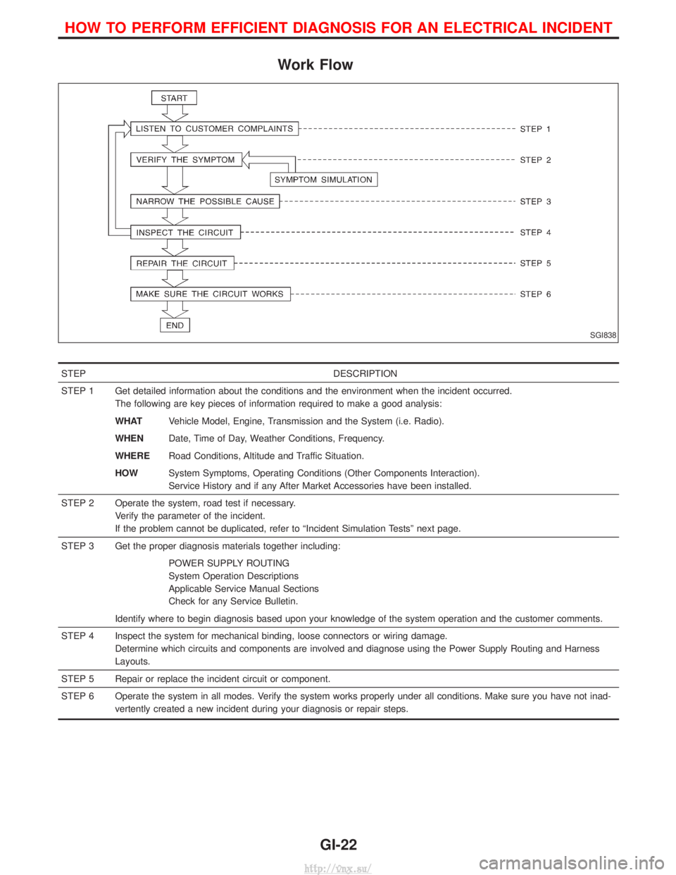
Work Flow
STEPDESCRIPTION
STEP 1 Get detailed information about the conditions and the environment when the incident occurred. The following are key pieces of information required to make a good analysis:
WHATVehicle Model, Engine, Transmission and the System (i.e. Radio).
WHEN Date, Time of Day, Weather Conditions, Frequency.
WHERE Road Conditions, Altitude and Traffic Situation.
HOW System Symptoms, Operating Conditions (Other Components Interaction).
Service History and if any After Market Accessories have been installed.
STEP 2 Operate the system, road test if necessary. Verify the parameter of the incident.
If the problem cannot be duplicated, refer to ªIncident Simulation Testsº next page.
STEP 3 Get the proper diagnosis materials together including: POWER SUPPLY ROUTING
System Operation Descriptions
Applicable Service Manual Sections
Check for any Service Bulletin.
Identify where to begin diagnosis based upon your knowledge of the system operation and the customer comments.
STEP 4 Inspect the system for mechanical binding, loose connectors or wiring damage. Determine which circuits and components are involved and diagnose using the Power Supply Routing and Harness
Layouts.
STEP 5 Repair or replace the incident circuit or component.
STEP 6 Operate the system in all modes. Verify the system works properly under all conditions. Make sure you have not inad- vertently created a new incident during your diagnosis or repair steps.
SGI838
HOW TO PERFORM EFFICIENT DIAGNOSIS FOR AN ELECTRICAL INCIDENT
GI-22
http://vnx.su/
Page 26 of 1833
Incident Simulation Tests
INTRODUCTION
Sometimes the symptom is not present when the vehicle is brought in for service. If possible, re-create the
conditions present at the time of the incident. Doing so may help avoid a No Trouble Found Diagnosis. The
following section illustrates ways to simulate the conditions/environment under which the owner experiences
an electrical incident.
The section is broken into the six following topics:
IVehicle vibration
I Heat sensitive
I Freezing
I Water intrusion
I Electrical load
I Cold or hot start up
Get a thorough description of the incident from the customer. It is important for simulating the conditions of
the problem.
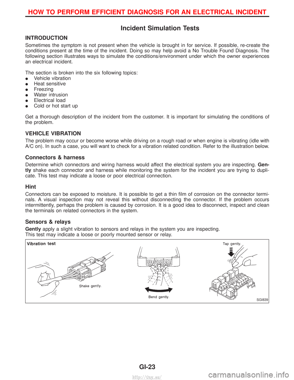
VEHICLE VIBRATION
The problem may occur or become worse while driving on a rough road or when engine is vibrating (idle with
A/C on). In such a case, you will want to check for a vibration related condition. Refer to the illustration below.
Connectors & harness
Determine which connectors and wiring harness would affect the electrical system you are inspecting. Gen-
tly shake each connector and harness while monitoring the system for the incident you are trying to dupli-
cate. This test may indicate a loose or poor electrical connection.
Hint
Connectors can be exposed to moisture. It is possible to get a thin film of corrosion on the connector termi-
nals. A visual inspection may not reveal this without disconnecting the connector. If the problem occurs
intermittently, perhaps the problem is caused by corrosion. It is a good idea to disconnect, inspect and clean
the terminals on related connectors in the system.
Sensors & relays
Gently apply a slight vibration to sensors and relays in the system you are inspecting.
This test may indicate a loose or poorly mounted sensor or relay.
SGI839
HOW TO PERFORM EFFICIENT DIAGNOSIS FOR AN ELECTRICAL INCIDENT
GI-23
http://vnx.su/
Page 27 of 1833
Engine compartment
There are several reasons a vehicle or engine vibration could
cause an electrical complaint. Some of the things to check for are:
IConnectors not fully seated.
I Wiring harness not long enough and is being stressed due to
engine vibrations or rocking.
I Wires laying across brackets or moving components.
I Loose, dirty or corroded ground wires.
I Wires routed too close to hot components.
To inspect components under the hood, start by verifying the integ-
rity of ground connections. (Refer to GROUND INSPECTION
described later.) First check that the system is properly grounded.
Then check for loose connection by gently shakingthe wiring or
components as previously explained. Using the wiring diagrams
inspect the wiring for continuity.
Behind the instrument panel
An improperly routed or improperly clamped harness can become
pinched during accessory installation. Vehicle vibration can aggra-
vate a harness which is routed along a bracket or near a screw.
Under seating areas
An unclamped or loose harness can cause wiring to be pinched by
seat components (such as slide guides) during vehicle vibration. If
the wiring runs under seating areas, inspect wire routing for pos-
sible damage or pinching.
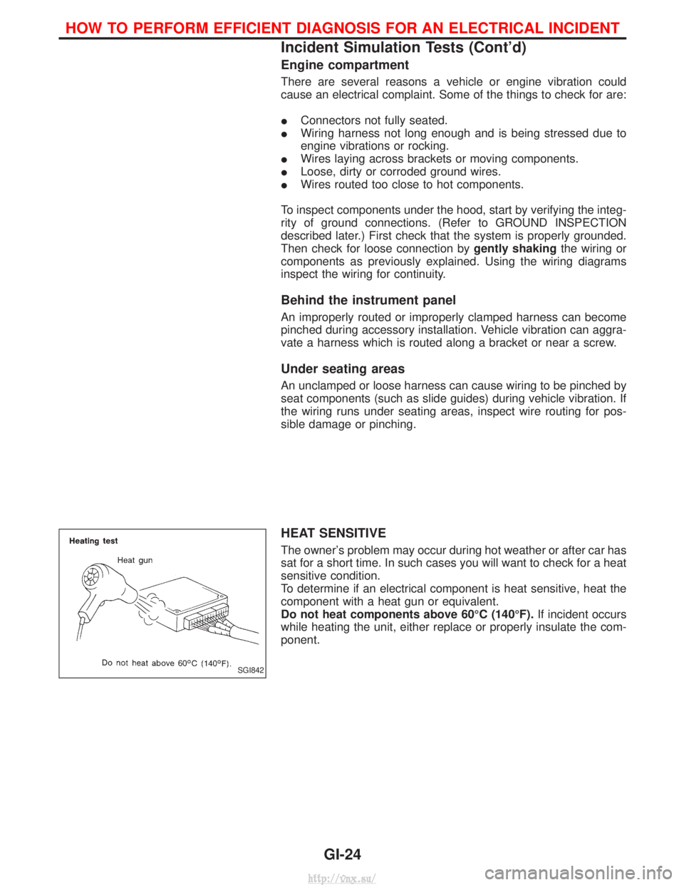
HEAT SENSITIVE
The owner's problem may occur during hot weather or after car has
sat for a short time. In such cases you will want to check for a heat
sensitive condition.
To determine if an electrical component is heat sensitive, heat the
component with a heat gun or equivalent.
Do not heat components above 60ÉC (140ÉF). If incident occurs
while heating the unit, either replace or properly insulate the com-
ponent.
SGI842
HOW TO PERFORM EFFICIENT DIAGNOSIS FOR AN ELECTRICAL INCIDENT
Incident Simulation Tests (Cont'd)
GI-24
http://vnx.su/
Page 28 of 1833
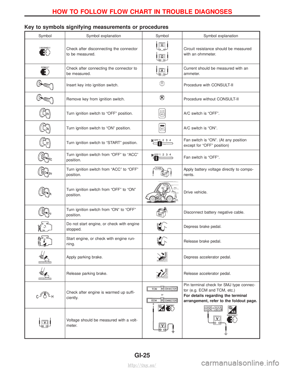
Key to symbols signifying measurements or procedures
SymbolSymbol explanation SymbolSymbol explanation
Check after disconnecting the connector
to be measured.Circuit resistance should be measured
with an ohmmeter.
Check after connecting the connector to
be measured.Current should be measured with an
ammeter.
Insert key into ignition switch.Procedure with CONSULT-II
Remove key from ignition switch.Procedure without CONSULT-II
Turn ignition switch to ªOFFº position.A/C switch is ªOFFº.
Turn ignition switch to ªONº position.A/C switch is ªONº.
Turn ignition switch to ªSTARTº position.Fan switch is ªONº. (At any position
except for ªOFFº position)
Turn ignition switch from ªOFFº to ªACCº
position.Fan switch is ªOFFº.
Turn ignition switch from ªACCº to ªOFFº
position.Apply battery voltage directly to compo-
nents.
Turn ignition switch from ªOFFº to ªONº
position.Drive vehicle.
Turn ignition switch from ªONº to ªOFFº
position.Disconnect battery negative cable.
Do not start engine, or check with engine
stopped.Depress brake pedal.
Start engine, or check with engine run-
ning.Release brake pedal.
Apply parking brake.Depress accelerator pedal.
Release parking brake.Release accelerator pedal.
Check after engine is warmed up suffi-
ciently.
Pin terminal check for SMJ type connec-
tor (e.g. ECM and TCM, etc.)
For details regarding the terminal
arrangement, refer to the foldout page.
Voltage should be measured with a volt-
meter.
HOW TO FOLLOW FLOW CHART IN TROUBLE DIAGNOSES
GI-25
http://vnx.su/
Page 29 of 1833
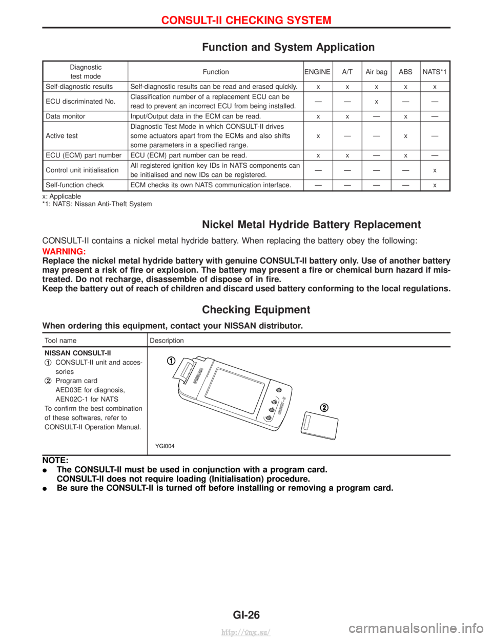
Function and System Application
Diagnostictest mode Function ENGINE A/T Air bag ABS NATS*1
Self-diagnostic results Self-diagnostic results can be read and erased quickly. xxxxx
ECU discriminated No. Classification number of a replacement ECU can be
read to prevent an incorrect ECU from being installed. ÐÐxÐÐ
Data monitor Input/Output data in the ECM can be read. x xÐxÐ
Active test Diagnostic Test Mode in which CONSULT-II drives
some actuators apart from the ECMs and also shifts
some parameters in a specified range. xÐÐxÐ
ECU (ECM) part number ECU (ECM) part number can be read. x xÐxÐ
Control unit initialisation All registered ignition key IDs in NATS components can
be initialised and new IDs can be registered. ÐÐÐÐ x
Self-function check ECM checks its own NATS communication interface. ÐÐÐÐ x
x: Applicable
*1: NATS: Nissan Anti-Theft System
Nickel Metal Hydride Battery Replacement
CONSULT-II contains a nickel metal hydride battery. When replacing the battery obey the following:
WARNING:
Replace the nickel metal hydride battery with genuine CONSULT-II battery only. Use of another battery
may present a risk of fire or explosion. The battery may present a fire or chemical burn hazard if mis-
treated. Do not recharge, disassemble of dispose of in fire.
Keep the battery out of reach of children and discard used battery conforming to the local regulations.
Checking Equipment
When ordering this equipment, contact your NISSAN distributor.
Tool name Description
NISSAN CONSULT-II
q
1CONSULT-II unit and acces-
sories
q
2Program card
AED03E for diagnosis,
AEN02C-1 for NATS
To confirm the best combination
of these softwares, refer to
CONSULT-II Operation Manual.
YGI004
NOTE:
I The CONSULT-II must be used in conjunction with a program card.
CONSULT-II does not require loading (Initialisation) procedure.
I Be sure the CONSULT-II is turned off before installing or removing a program card.
CONSULT-II CHECKING SYSTEM
GI-26
http://vnx.su/
Page 38 of 1833
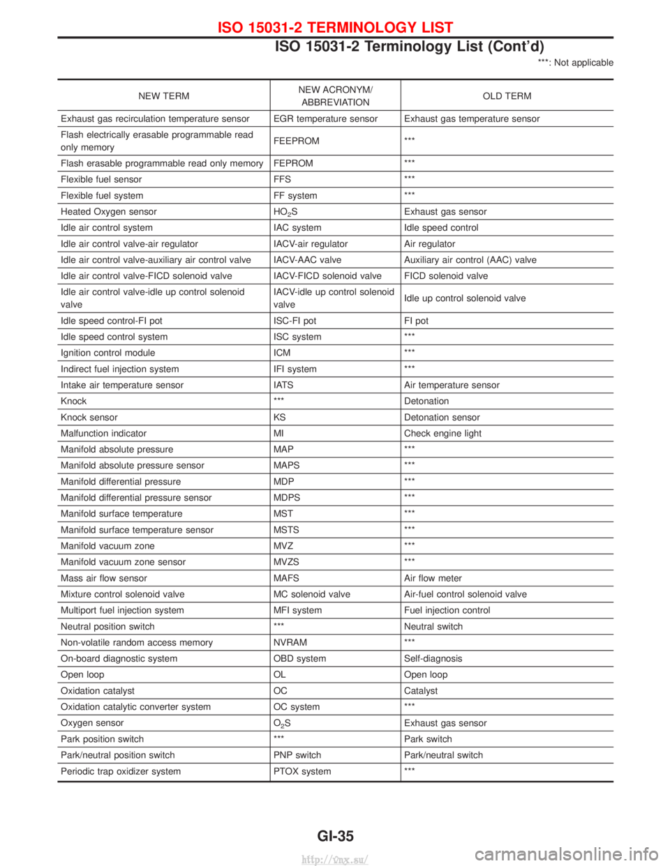
***: Not applicable
NEW TERMNEW ACRONYM/
ABBREVIATION OLD TERM
Exhaust gas recirculation temperature sensor EGR temperature sensor Exhaust gas temperature sensor
Flash electrically erasable programmable read
only memory FEEPROM ***
Flash erasable programmable read only memory FEPROM ***
Flexible fuel sensor FFS ***
Flexible fuel system FF system ***
Heated Oxygen sensor HO
2S Exhaust gas sensor
Idle air control system IAC systemIdle speed control
Idle air control valve-air regulator IACV-air regulatorAir regulator
Idle air control valve-auxiliary air control valve IACV-AAC valve Auxiliary air control (AAC) valve
Idle air control valve-FICD solenoid valve IACV-FICD solenoid valve FICD solenoid valve
Idle air control valve-idle up control solenoid
valve IACV-idle up control solenoid
valve
Idle up control solenoid valve
Idle speed control-FI pot ISC-FI potFI pot
Idle speed control system ISC system***
Ignition control module ICM***
Indirect fuel injection system IFI system***
Intake air temperature sensor IATS Air temperature sensor
Knock *** Detonation
Knock sensor KS Detonation sensor
Malfunction indicator MI Check engine light
Manifold absolute pressure MAP ***
Manifold absolute pressure sensor MAPS ***
Manifold differential pressure MDP ***
Manifold differential pressure sensor MDPS ***
Manifold surface temperature MST ***
Manifold surface temperature sensor MSTS ***
Manifold vacuum zone MVZ ***
Manifold vacuum zone sensor MVZS ***
Mass air flow sensor MAFS Air flow meter
Mixture control solenoid valve MC solenoid valve Air-fuel control solenoid valve
Multiport fuel injection system MFI system Fuel injection control
Neutral position switch *** Neutral switch
Non-volatile random access memory NVRAM ***
On-board diagnostic system OBD system Self-diagnosis
Open loop OL Open loop
Oxidation catalyst OC Catalyst
Oxidation catalytic converter system OC system ***
Oxygen sensor O
2S Exhaust gas sensor
Park position switch ***Park switch
Park/neutral position switch PNP switch Park/neutral switch
Periodic trap oxidizer system PTOX system ***
ISO 15031-2 TERMINOLOGY LIST
ISO 15031-2 Terminology List (Cont'd)
GI-35
http://vnx.su/