weight NISSAN TERRANO 2004 Service Repair Manual
[x] Cancel search | Manufacturer: NISSAN, Model Year: 2004, Model line: TERRANO, Model: NISSAN TERRANO 2004Pages: 1833, PDF Size: 53.42 MB
Page 5 of 1833
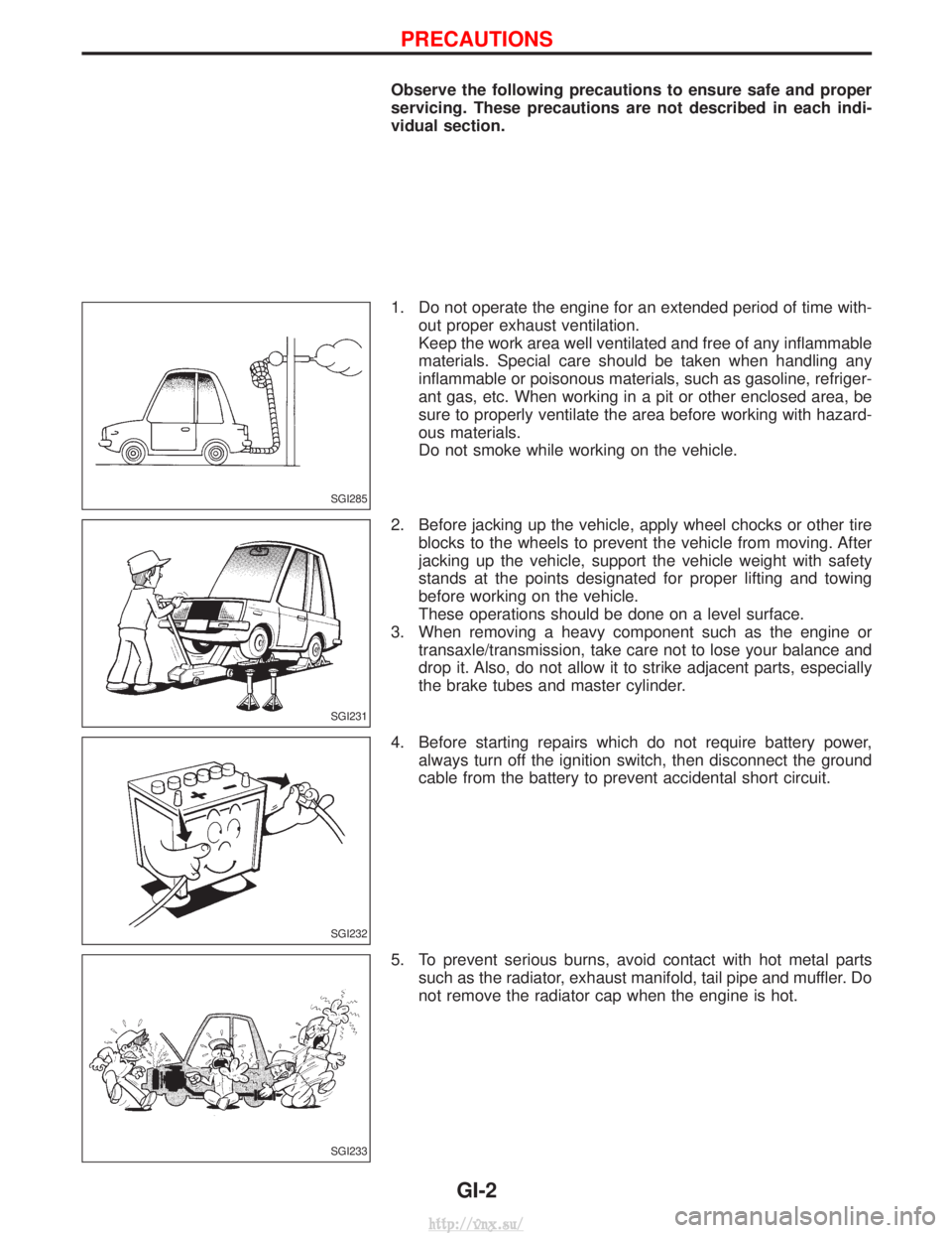
Observe the following precautions to ensure safe and proper
servicing. These precautions are not described in each indi-
vidual section.
1. Do not operate the engine for an extended period of time with-out proper exhaust ventilation.
Keep the work area well ventilated and free of any inflammable
materials. Special care should be taken when handling any
inflammable or poisonous materials, such as gasoline, refriger-
ant gas, etc. When working in a pit or other enclosed area, be
sure to properly ventilate the area before working with hazard-
ous materials.
Do not smoke while working on the vehicle.
2. Before jacking up the vehicle, apply wheel chocks or other tire blocks to the wheels to prevent the vehicle from moving. After
jacking up the vehicle, support the vehicle weight with safety
stands at the points designated for proper lifting and towing
before working on the vehicle.
These operations should be done on a level surface.
3. When removing a heavy component such as the engine or transaxle/transmission, take care not to lose your balance and
drop it. Also, do not allow it to strike adjacent parts, especially
the brake tubes and master cylinder.
4. Before starting repairs which do not require battery power, always turn off the ignition switch, then disconnect the ground
cable from the battery to prevent accidental short circuit.
5. To prevent serious burns, avoid contact with hot metal parts such as the radiator, exhaust manifold, tail pipe and muffler. Do
not remove the radiator cap when the engine is hot.
SGI285
SGI231
SGI232
SGI233
PRECAUTIONS
GI-2
http://vnx.su/
Page 19 of 1833
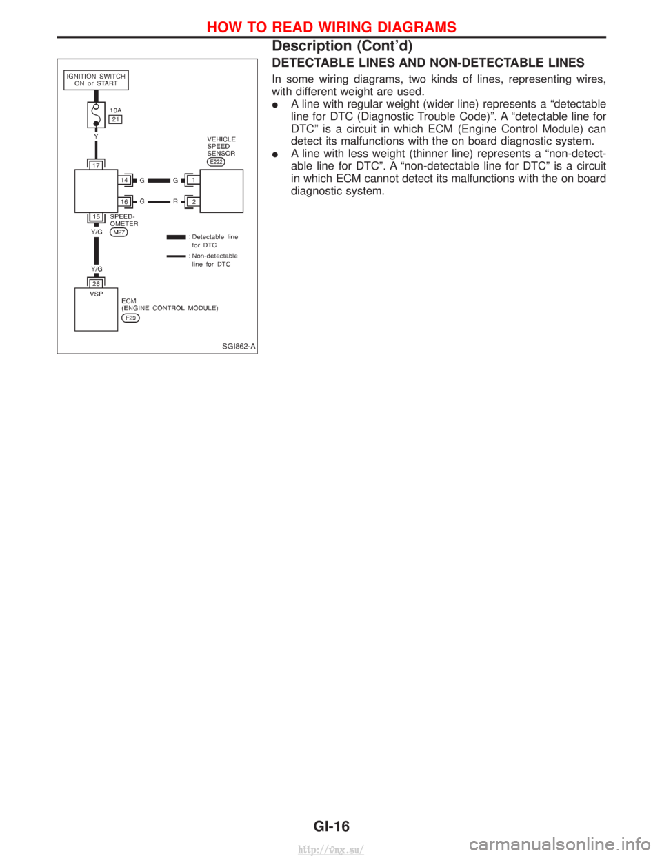
DETECTABLE LINES AND NON-DETECTABLE LINES
In some wiring diagrams, two kinds of lines, representing wires,
with different weight are used.
IA line with regular weight (wider line) represents a ªdetectable
line for DTC (Diagnostic Trouble Code)º. A ªdetectable line for
DTCº is a circuit in which ECM (Engine Control Module) can
detect its malfunctions with the on board diagnostic system.
I A line with less weight (thinner line) represents a ªnon-detect-
able line for DTCº. A ªnon-detectable line for DTCº is a circuit
in which ECM cannot detect its malfunctions with the on board
diagnostic system.
SGI862-A
HOW TO READ WIRING DIAGRAMS
Description (Cont'd)
GI-16
http://vnx.su/
Page 35 of 1833
4-pole Lift
WARNING:
Do not use a 2-pole lift.
Due to weight balance of the vehicle and shape of underbody,
lift arms can not be attached in a safe way. Therefore it is rec-
ommended to use a 4-pole lift only.
Tow Truck Towing
CAUTION:
IAll applicable local laws regarding the towing operation
must be obeyed.
I It is necessary to use proper towing equipment to avoid
possible damage to the vehicle during a towing operation.
I Attach safety chains for all towing.
I When towing, make sure that the transmission, steering
system and power train are in good order. If any unit is
damaged, a dolly must be used.
I When towing with the front wheels on the ground:
Move both the gearshift and transfer levers to neutral (ªNº
position).
Turn the ignition key to the ªOFFº position and secure the
steering wheel in a straightahead position with a rope or
similar device. Never place the ignition key in the ªLOCKº
position. This will result in damage to the steering lock
mechanism.
I When towing with the rear wheels on the ground, release
the parking brake and move both the gearshift and trans-
fer levers to neutral (ªNº position).
I Never tow vehicle from the rear (i.e., backward) with four
wheels on the ground as this may cause serious and
expensive damage to the transmission.
LIFTING POINTS AND TOW TRUCK TOWING
GI-32
http://vnx.su/
Page 131 of 1833
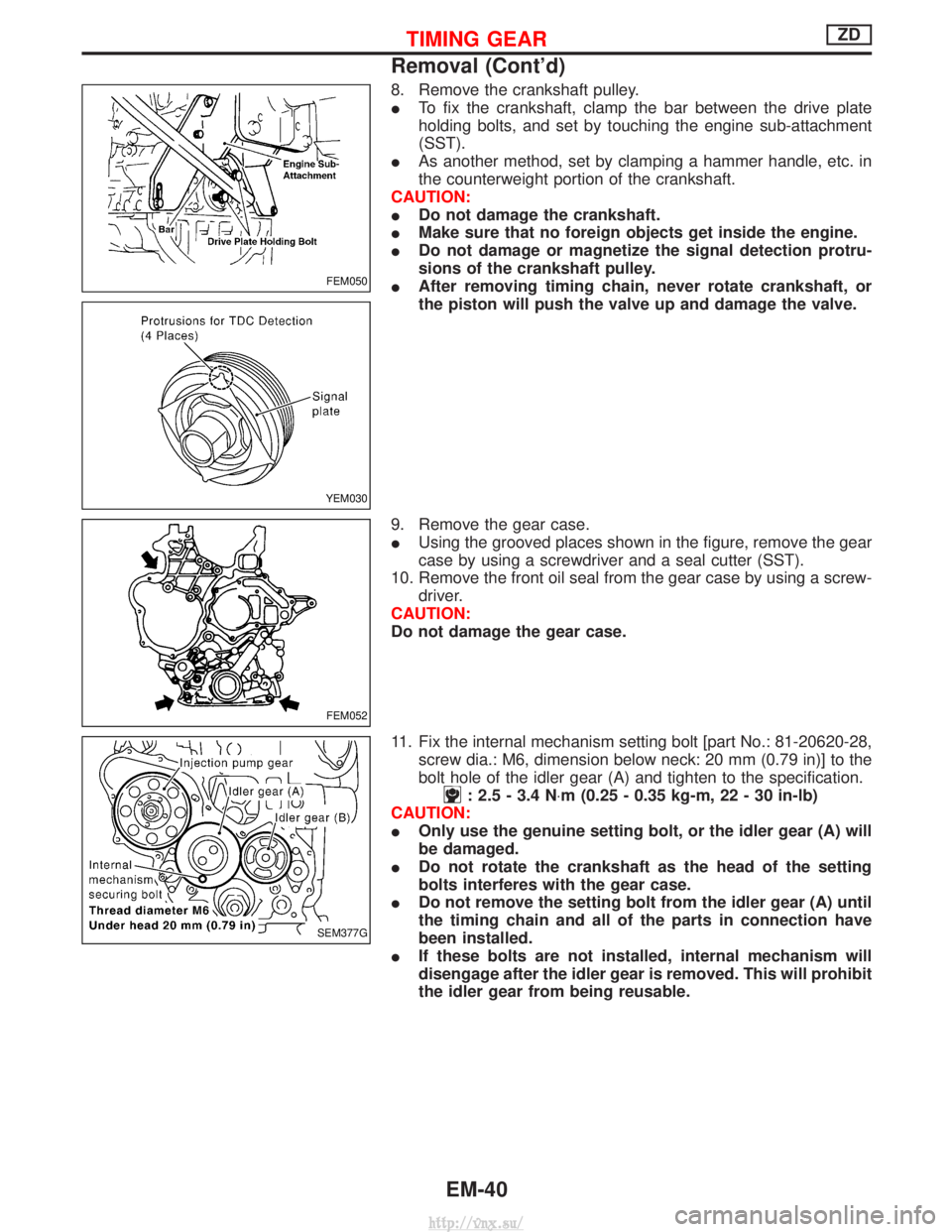
8. Remove the crankshaft pulley.
ITo fix the crankshaft, clamp the bar between the drive plate
holding bolts, and set by touching the engine sub-attachment
(SST).
I As another method, set by clamping a hammer handle, etc. in
the counterweight portion of the crankshaft.
CAUTION:
I Do not damage the crankshaft.
I Make sure that no foreign objects get inside the engine.
I Do not damage or magnetize the signal detection protru-
sions of the crankshaft pulley.
I After removing timing chain, never rotate crankshaft, or
the piston will push the valve up and damage the valve.
9. Remove the gear case.
I Using the grooved places shown in the figure, remove the gear
case by using a screwdriver and a seal cutter (SST).
10. Remove the front oil seal from the gear case by using a screw- driver.
CAUTION:
Do not damage the gear case.
11. Fix the internal mechanism setting bolt [part No.: 81-20620-28, screw dia.: M6, dimension below neck: 20 mm (0.79 in)] to the
bolt hole of the idler gear (A) and tighten to the specification.
: 2.5 - 3.4 N ×m (0.25 - 0.35 kg-m, 22 - 30 in-lb)
CAUTION:
I Only use the genuine setting bolt, or the idler gear (A) will
be damaged.
I Do not rotate the crankshaft as the head of the setting
bolts interferes with the gear case.
I Do not remove the setting bolt from the idler gear (A) until
the timing chain and all of the parts in connection have
been installed.
I If these bolts are not installed, internal mechanism will
disengage after the idler gear is removed. This will prohibit
the idler gear from being reusable.
FEM050
YEM030
FEM052
SEM377G
TIMING GEARZD
Removal (Cont'd)
EM-40
http://vnx.su/
Page 165 of 1833
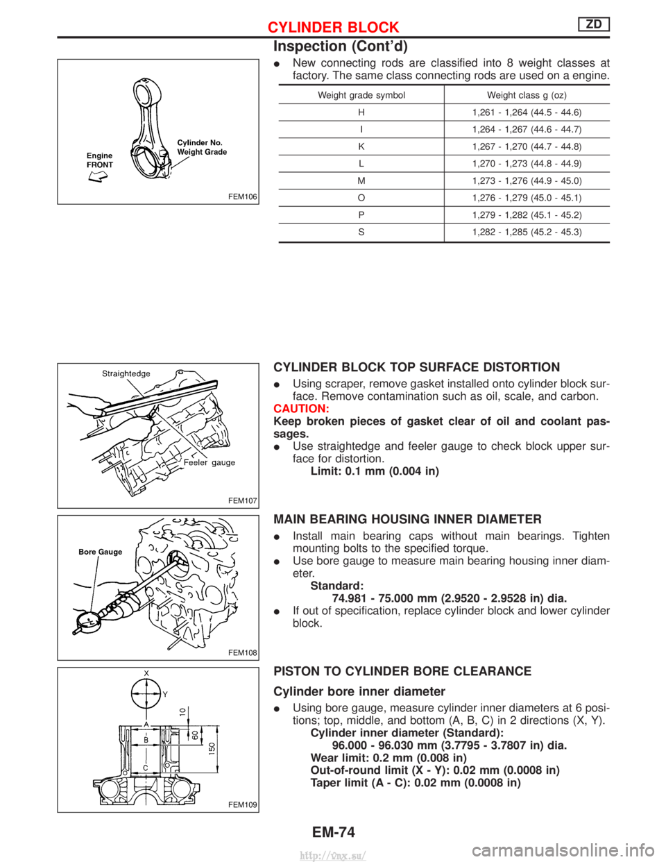
INew connecting rods are classified into 8 weight classes at
factory. The same class connecting rods are used on a engine.
Weight grade symbol Weight class g (oz)
H 1,261 - 1,264 (44.5 - 44.6) I 1,264 - 1,267 (44.6 - 44.7)
K 1,267 - 1,270 (44.7 - 44.8) L 1,270 - 1,273 (44.8 - 44.9)
M 1,273 - 1,276 (44.9 - 45.0) O 1,276 - 1,279 (45.0 - 45.1) P 1,279 - 1,282 (45.1 - 45.2)
S 1,282 - 1,285 (45.2 - 45.3)
CYLINDER BLOCK TOP SURFACE DISTORTION
I Using scraper, remove gasket installed onto cylinder block sur-
face. Remove contamination such as oil, scale, and carbon.
CAUTION:
Keep broken pieces of gasket clear of oil and coolant pas-
sages.
I Use straightedge and feeler gauge to check block upper sur-
face for distortion.
Limit: 0.1 mm (0.004 in)
MAIN BEARING HOUSING INNER DIAMETER
I Install main bearing caps without main bearings. Tighten
mounting bolts to the specified torque.
I Use bore gauge to measure main bearing housing inner diam-
eter.
Standard: 74.981 - 75.000 mm (2.9520 - 2.9528 in) dia.
I If out of specification, replace cylinder block and lower cylinder
block.
PISTON TO CYLINDER BORE CLEARANCE
Cylinder bore inner diameter
IUsing bore gauge, measure cylinder inner diameters at 6 posi-
tions; top, middle, and bottom (A, B, C) in 2 directions (X, Y).
Cylinder inner diameter (Standard): 96.000 - 96.030 mm (3.7795 - 3.7807 in) dia.
Wear limit: 0.2 mm (0.008 in)
Out-of-round limit (X - Y): 0.02 mm (0.0008 in)
Taper limit (A - C): 0.02 mm (0.0008 in)
FEM106
FEM107
FEM108
FEM109
CYLINDER BLOCKZD
Inspection (Cont'd)
EM-74
http://vnx.su/
Page 167 of 1833
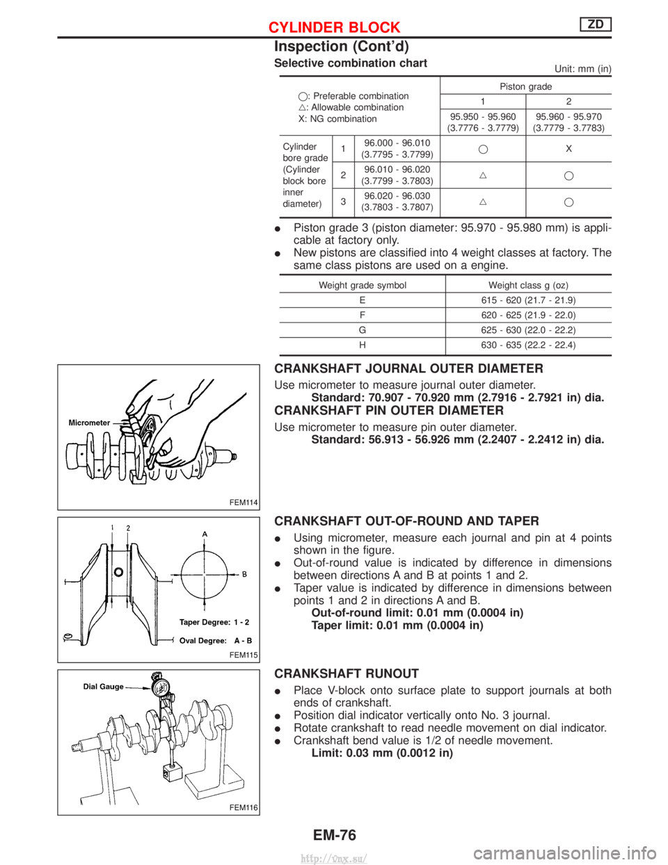
Selective combination chartUnit: mm (in)
q: Preferable combination
g: Allowable combination
X: NG combinationPiston grade
12
95.950 - 95.960
(3.7776 - 3.7779) 95.960 - 95.970
(3.7779 - 3.7783)
Cylinder
bore grade
(Cylinder
block bore
inner
diameter) 1
96.000 - 96.010
(3.7795 - 3.7799) q
X
2 96.010 - 96.020
(3.7799 - 3.7803) gq
3 96.020 - 96.030
(3.7803 - 3.7807) gq
I
Piston grade 3 (piston diameter: 95.970 - 95.980 mm) is appli-
cable at factory only.
I New pistons are classified into 4 weight classes at factory. The
same class pistons are used on a engine.
Weight grade symbol Weight class g (oz)
E 615 - 620 (21.7 - 21.9) F 620 - 625 (21.9 - 22.0)
G 625 - 630 (22.0 - 22.2) H 630 - 635 (22.2 - 22.4)
CRANKSHAFT JOURNAL OUTER DIAMETER
Use micrometer to measure journal outer diameter. Standard: 70.907 - 70.920 mm (2.7916 - 2.7921 in) dia.
CRANKSHAFT PIN OUTER DIAMETER
Use micrometer to measure pin outer diameter.Standard: 56.913 - 56.926 mm (2.2407 - 2.2412 in) dia.
CRANKSHAFT OUT-OF-ROUND AND TAPER
IUsing micrometer, measure each journal and pin at 4 points
shown in the figure.
I Out-of-round value is indicated by difference in dimensions
between directions A and B at points 1 and 2.
I Taper value is indicated by difference in dimensions between
points 1 and 2 in directions A and B.
Out-of-round limit: 0.01 mm (0.0004 in)
Taper limit: 0.01 mm (0.0004 in)
CRANKSHAFT RUNOUT
I Place V-block onto surface plate to support journals at both
ends of crankshaft.
I Position dial indicator vertically onto No. 3 journal.
I Rotate crankshaft to read needle movement on dial indicator.
I Crankshaft bend value is 1/2 of needle movement.
Limit: 0.03 mm (0.0012 in)
FEM114
FEM115
FEM116
CYLINDER BLOCKZD
Inspection (Cont'd)
EM-76
http://vnx.su/
Page 222 of 1833
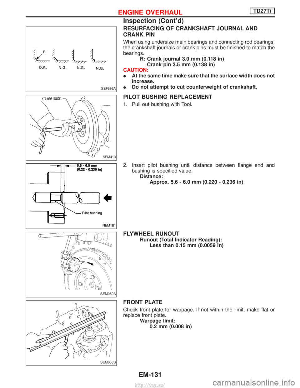
RESURFACING OF CRANKSHAFT JOURNAL AND
CRANK PIN
When using undersize main bearings and connecting rod bearings,
the crankshaft journals or crank pins must be finished to match the
bearings.R: Crank journal 3.0 mm (0.118 in)Crank pin 3.5 mm (0.138 in)
CAUTION:
I At the same time make sure that the surface width does not
increase.
I Do not attempt to cut counterweight of crankshaft.
PILOT BUSHING REPLACEMENT
1. Pull out bushing with Tool.
2. Insert pilot bushing until distance between flange end and
bushing is specified value.Distance: Approx. 5.6 - 6.0 mm (0.220 - 0.236 in)
FLYWHEEL RUNOUT
Runout (Total Indicator Reading):Less than 0.15 mm (0.0059 in)
FRONT PLATE
Check front plate for warpage. If not within the limit, make flat or
replace front plate. Warpage limit:0.2 mm (0.008 in)
SEF692A
SEM413
NEM181
SEM059A
SEM668B
ENGINE OVERHAULTD27Ti
Inspection (Cont'd)
EM-131
http://vnx.su/
Page 247 of 1833
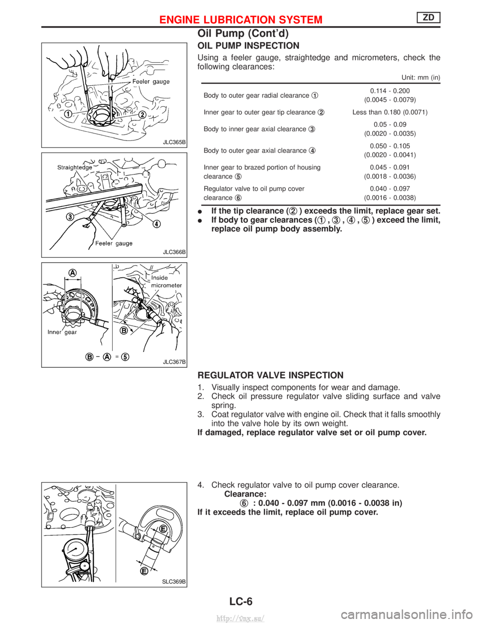
OIL PUMP INSPECTION
Using a feeler gauge, straightedge and micrometers, check the
following clearances:
Unit: mm (in)
Body to outer gear radial clearanceq10.114 - 0.200
(0.0045 - 0.0079)
Inner gear to outer gear tip clearance q
2Less than 0.180 (0.0071)
Body to inner gear axial clearance q
30.05 - 0.09
(0.0020 - 0.0035)
Body to outer gear axial clearance q
40.050 - 0.105
(0.0020 - 0.0041)
Inner gear to brazed portion of housing
clearance q
5
0.045 - 0.091
(0.0018 - 0.0036)
Regulator valve to oil pump cover
clearance q
6
0.040 - 0.097
(0.0016 - 0.0038)
I If the tip clearance ( q2) exceeds the limit, replace gear set.
I If body to gear clearances ( q
1,q3,q4,q5) exceed the limit,
replace oil pump body assembly.
REGULATOR VALVE INSPECTION
1. Visually inspect components for wear and damage.
2. Check oil pressure regulator valve sliding surface and valve spring.
3. Coat regulator valve with engine oil. Check that it falls smoothly into the valve hole by its own weight.
If damaged, replace regulator valve set or oil pump cover.
4. Check regulator valve to oil pump cover clearance. Clearance:q
6: 0.040 - 0.097 mm (0.0016 - 0.0038 in)
If it exceeds the limit, replace oil pump cover.
JLC365B
JLC366B
JLC367B
SLC369B
ENGINE LUBRICATION SYSTEMZD
Oil Pump (Cont'd)
LC-6
http://vnx.su/
Page 265 of 1833
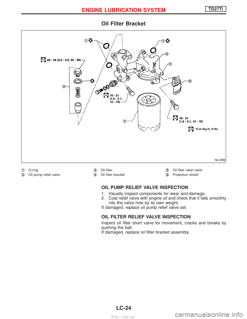
Oil Filter Bracket
q1O-ring
q
2Oil pump relief valve q
3Oil filter
q
4Oil filter bracket q
5Oil filter relief valve
q
6Protection shield
OIL PUMP RELIEF VALVE INSPECTION
1. Visually inspect components for wear and damage.
2. Coat relief valve with engine oil and check that it falls smoothly into the valve hole by its own weight.
If damaged, replace oil pump relief valve set.
OIL FILTER RELIEF VALVE INSPECTION
Inspect oil filter short valve for movement, cracks and breaks by
pushing the ball.
If damaged, replace oil filter bracket assembly.
NLC056
ENGINE LUBRICATION SYSTEMTD27Ti
LC-24
http://vnx.su/
Page 266 of 1833
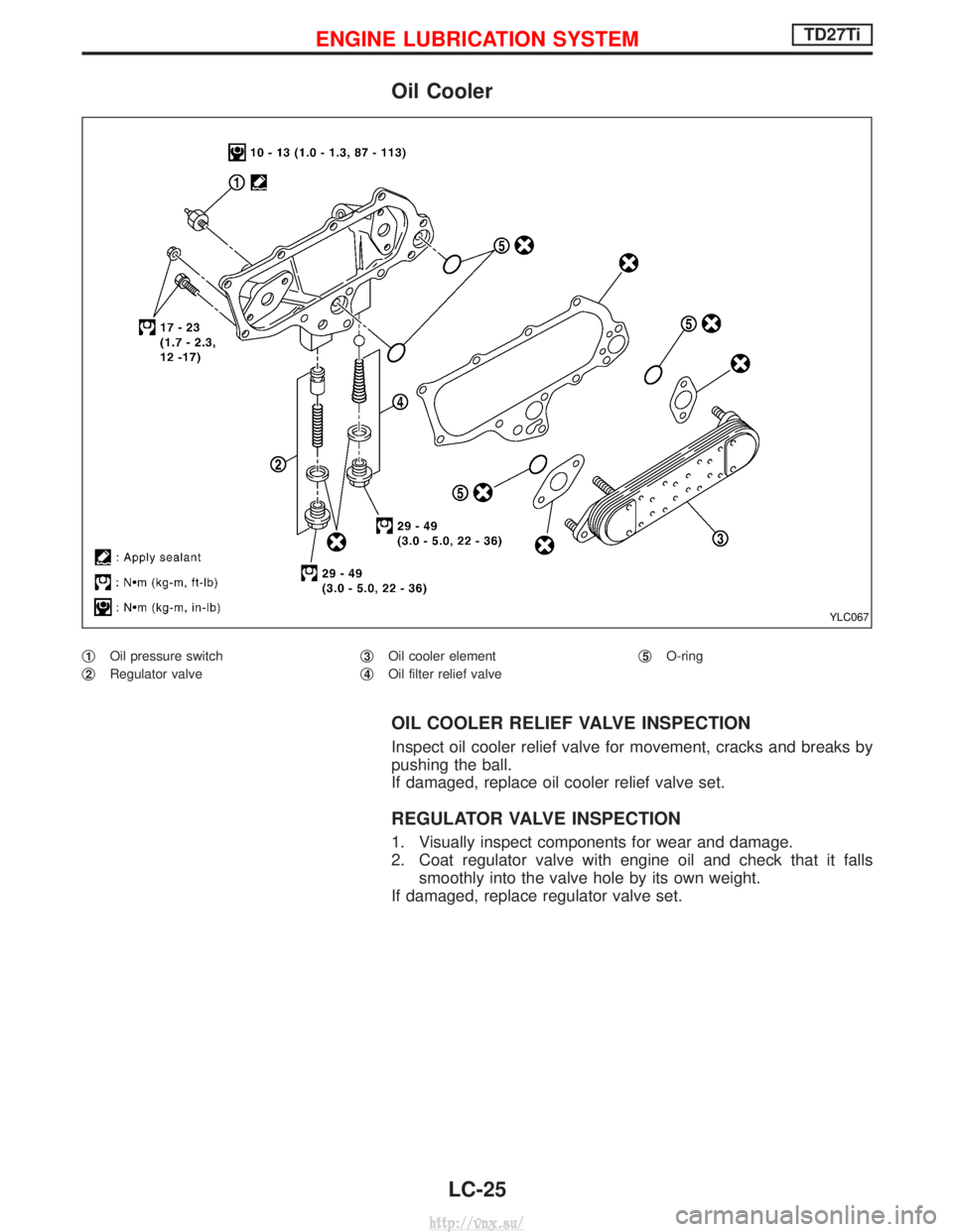
Oil Cooler
q1Oil pressure switch
q
2Regulator valve q
3Oil cooler element
q
4Oil filter relief valve q
5O-ring
OIL COOLER RELIEF VALVE INSPECTION
Inspect oil cooler relief valve for movement, cracks and breaks by
pushing the ball.
If damaged, replace oil cooler relief valve set.
REGULATOR VALVE INSPECTION
1. Visually inspect components for wear and damage.
2. Coat regulator valve with engine oil and check that it falls
smoothly into the valve hole by its own weight.
If damaged, replace regulator valve set.
YLC067
ENGINE LUBRICATION SYSTEMTD27Ti
LC-25
http://vnx.su/